Second-Harmonic Generation - users-deprecated.aims.ac.za
Second-Harmonic Generation - users-deprecated.aims.ac.za
Second-Harmonic Generation - users-deprecated.aims.ac.za

You also want an ePaper? Increase the reach of your titles
YUMPU automatically turns print PDFs into web optimized ePapers that Google loves.
<strong>Second</strong>-<strong>Harmonic</strong> <strong>Generation</strong>Victoria Nwosu (victoria@<strong>aims</strong>.<strong>ac</strong>.<strong>za</strong>)African Institute for Mathematical Sciences (AIMS)Supervised by Prof. E.G. Rohwer and Dr. G.J. ArendseUniversity of Stellenbosch, South AfricaMay 24, 2007
Abstr<strong>ac</strong>tThe basic principles underlying the generation of a second-harmonic wave in dielectric materialswere studied. Solving Maxwell’s equations, it was discovered theoretically that when light withhigh intensity is incident on a nonlinear crystal, then a wave doubling the frequency of theincident light called the second-harmonic wave can be obtained by proper phase matching thefundamental and the second-harmonic waves. The intensity of the second-harmonic wave wasshown to increase as the square of the intensity of the fundamental field under the approximationthat the fundamental field was undepleted in the medium. However, experimental results showedthat, due to the the depletion of the fundamental wave as it passes through the medium, theincrease of the intensity of the second-harmonic signal as the square of the fundamental wavere<strong>ac</strong>hes a saturation point, from which the intensity of the second-harmonic wave maintains <strong>ac</strong>onstant value.i
A Code for the computation of the variation of the refr<strong>ac</strong>tive index with frequency 31A.1 A code for the dispersion curve . . . . . . . . . . . . . . . . . . . . . . . . . . 31A.2 A code for the imaginary part of the refr<strong>ac</strong>tive index . . . . . . . . . . . . . . . 31B Code to Compute Reduction in the <strong>Second</strong> <strong>Harmonic</strong> <strong>Generation</strong> and CoherenceLength 33B.1 Coherence length . . . . . . . . . . . . . . . . . . . . . . . . . . . . . . . . . . 33C Code for ploting the Intensity of the <strong>Second</strong>-<strong>Harmonic</strong> Signal 34C.1 Fitted Quadratic Polynomial on the <strong>Generation</strong> of the <strong>Second</strong>-<strong>Harmonic</strong> Signal . 34Bibliography 37iii
List of Figures1.1 Imaginary part of the refr<strong>ac</strong>tive index versus frequency, ω 0 = 20 . . . . . . . . . 71.2 Real part of the refr<strong>ac</strong>tive index versus frequency ω 0 = 20 . . . . . . . . . . . . 72.1 Energy level description of second harmonic generation from a quantum standpoint. 162.2 Energy level description of sum-frequency generation from a quantum standpoint. 182.3 Energy level description of difference-frequency generation form a quantum standpoint.. . . . . . . . . . . . . . . . . . . . . . . . . . . . . . . . . . . . . . . . 183.1 Intensity of the second-harmonic signal versus the average input power . . . . . 243.2 Schematic experimental arrangement for detection of second-harmonic generation,where ω is the frequency of the incident laser beam. . . . . . . . . . . . . . . . 253.3 The graph of f(L) = (sin2 αL)(αL) 2 , where α ≡ ∆k/2. . . . . . . . . . . . . . . . . . 263.4 Geometry for angle phase matching of second-harmonic generation. . . . . . . . 28iv
1. General B<strong>ac</strong>kground1.1 IntroductionLaser physics and nonlinear optics are fields which have been intimately connected from theirbeginning[1]. Nonlinear optics, includes frequency conversions, and these new frequency generationprocesses has found its applications in different research areas including spectroscopy.Preceding the invention of lasers, the optical effects observed in materials as light passes throughit has been treated in a linear manner, but with the invention of laser light with high intensities,interesting nonlinear optical effects have now been observed and studied. Nonlinear optics is thestudy of the phenomena that occur as a consequence of the enhancement of the optical propertiesof a material system by the presence of light with high intensity. Typically, only laser light issufficiently intense to bring to the fore the nonlinear optical properties of a material. In f<strong>ac</strong>t, thebeginning of the field of nonlinear optics is often taken to be the discovery of second-harmonicgeneration by Fraken et al in 1961 [2].The phenomena are nonlinear in the sense that the response of a material to an applied opticalfield depends in a nonlinear manner upon the strength of the incident electric field. For example,second-harmonic generation occurs as a result of the part of the atomic response that depends onthe square of the strength of the applied field. Consequently, the intensity of the light generatedat the second-harmonic frequency tends to increase as the square of the intensity of the appliedlaser light[3]. This effect is discussed in detail in Section 3.1. In essence, we mean that forsecond-harmonic generation if we send in a laser light of about 694 nm we can observe an outputlight of double the frequency and so half the wavelength of the light at 347 nm. The basicquestions then are; why are we able to observe this and how can this be efficiently generated?This work tries to explain the conditions under which this effect can be observed and how secondharmonic generation can be efficiently generated. Since second-harmonic generation is a nonlinearoptical process, we will need to first understand how the linear process works, that is what wewill explain in Chapter 1, the linear response of materials to an applied field and introduce thenonlinear effects. In Chapter 2 we will explain the nonlinear wave Equation and briefly explainthe different second order nonlinear processes. In Chapter 3 we will explain how the efficiency ofthe second- harmonic generation is maximised and conclude this work with Chapter 4.1.2 Linear Polarisation of a Dielectric MediumConsider a dielectric medium (non-conducting) whose properties are isotropic. Application of afield to such a medium causes charge displ<strong>ac</strong>ement, in which the negative charge distributionbound to the nuclei shifts in a direction opposite to the electric field while the positive end ofthe dipole is in the direction of the field . The dipole moment p due to e<strong>ac</strong>h atom is given bythe product of the displ<strong>ac</strong>ed charge q and the effective separation r of the positive and negativecharge of the atomic dipolep = −qr.1
Section 1.3. Electron Oscillation Model and Linear Polarisation Page 2The polarisation P of the medium is then said to be the collective dipole moment per unit volume,given byP = −Ner, (1.1)where N is the number of elementary particles per volume, e is the magnitude of the electroniccharge and r is a vector representing the distance the charge −e is displ<strong>ac</strong>ed from its equilibriumposition.1.3 Electron Oscillation Model and Linear PolarisationLet us assume that electrons behave as though the forces binding them to the nuclei are elasticforces described by Hooke’s law, this means we are considering a linear response, where therestoring force is proportional to the displ<strong>ac</strong>ement and oppositely directed. We can use this ideato obtain an expression for the polarisation in terms of the frequency of the applied field. Theforce on the electron due to the electric field isF = eE = −Kr, (1.2)where K is the restoring force constant. In Section 1.7 we shall consider additional nonlinearterms. Equation (1.2) leads to the formula for the static polarisation.P = Ne2 EK . (1.3)If the applied field varies with time, then Equation (1.3) no more holds. Using Newton’s secondlaw the Equation of motion of the localised charges now becomeswhich can be written asF = m d2 r= −Kr = −eE, (1.4)dt2 m d2 rdt + mγdr + Kr = −eE. (1.5)2 dtHere, mγ dr is the frictional damping term. We will assume that the time dependence of thedtelectron motion has a solution of the form r = r 0 e iωt , here ω is the angular oscillation frequency.Equation (1.5) leads to an Equation of the form(−mω 2 − iωmγ + K ) r = −eE. (1.6)Solving for r we getr =−eE(−mω 2 − iωmγ + K)(1.7)and substituting in (1.1), we get a value for P as(P = P(ω) =Ne 2−mω 2 − iωmγ + K)E. (1.8)
Section 1.4. Wave Equation in a Medium and Linear Polarisation Page 3This solution gives the static value for P at ω = 0 as would be expected and this also shows thatthe response of the polarisation to the applied electric field is frequency dependent. Dividing thenumerator and the denominator of the right-hand side of Equation (1.8) by m and defining aresonant angular frequency ω 0 and oscillating frequency ν 0 asP then transforms toω 0 ≡(P =( Km) 12= 2πν0 , (1.9)Ne 2 /mω 2 0 − ω 2 − iωγ)E. (1.10)The resonant frequency ω 0 corresponds to that of a simple harmonic oscillator, and is strictlyassociated with the properties of the material and not of the electric field inter<strong>ac</strong>ting with thematerial. Electrons are most easily perturbed or excited at the resonant frequency. The quantityin the br<strong>ac</strong>ket is referred to as the linear susceptibility of the material, often represented as χ,and is often a property of the material since it enhances the linear polarisation P when resonanceis <strong>ac</strong>hieved. The linear polarisation of the material is then expressed asP = ɛ 0 χE. (1.11)1.4 Wave Equation in a Medium and Linear PolarisationIn this Section we will derive the wave Equation for the linear polarisation of a medium, and wewill also look at the nature of the wave vector k propagating in the medium.When we apply Maxwell’s Equations to non-magnetic materials, and taking the magnetisationM = 0, Maxwell’s Equations then become[2]∇ · E = − 1 ɛ 0∇ · P, (1.12)and∇ · H = 0, (1.13)∂E∇ × H = ɛ 0∂t + ∂P + J, (1.14)∂t∇ × E = −µ 0∂H∂t . (1.15)J is the electric current density. Taking the curl of Equation (1.15) and the time derivativeof Equation (1.14) we get∇ × (∇ × E) + 1 c 2 ∂ 2 E∂t 2= −µ 0∂ 2 P∂t 2 − µ 0∂J∂t . (1.16)
Section 1.5. Linear Polarisation and Refr<strong>ac</strong>tive Index Page 5andk 2 = ω2c 2 [1 +( ) Ne2m]1ω0 2 − . (1.20)ω2 − iγωFrom this we can conclude that a plane wave propagation in a homogeneous dielectric requires ingeneral that the propagation constant k be a complex number. Defining the real and imaginaryparts of k by˜k = k R + ik Iand repl<strong>ac</strong>ing this form into the expression for a harmonic wave as in Equation (1.19), we getE = E 0 e i((k R+ik I z)−ωt) = E 0 e k Iz e i(k Rz−ωt) . (1.21)Taking the square of the magnitude of both sides gives|E| 2 = E 2 0e −2k Iz .The intensity of a field passing through a dielectric medium is given by [4]I = 1 2 ɛ η0v |E|2 , (1.22)where η is the refr<strong>ac</strong>tive index of the medium, v is the speed of the wave in the medium and cis the speed of light. Therefore,I = 1 2 ɛ η0v E 0e −2kIz = I 0 e −2kIz = I 0 e −αz . (1.23)where α = 2k I is the absorption coefficient of the medium, and it determines how much of theincoming light is absorbed by the medium.1.5 Linear Polarisation and Refr<strong>ac</strong>tive IndexIn this Section, we would like explain how the refr<strong>ac</strong>tive index of light in a medium depends onthe frequency of the light. Understanding this will help us later in Chapter 2 and 3 when wewill discuss the effect of the different refr<strong>ac</strong>tive indices for the fundamental and second harmonicwave.Since the propagation constant is complex (see Equation 1.20), so is the refr<strong>ac</strong>tive index becausek = 2π λ = 2πfvWriting out the real and imaginary parts of the refr<strong>ac</strong>tive index, we get=( ωc)η. (1.24)η = η R + iη I . (1.25)
Section 1.5. Linear Polarisation and Refr<strong>ac</strong>tive Index Page 6So from (1.24)yielding the relationsandk R + ik I =( ωc)(η R + iη I )k R = ω c η R,k I = ω c η I.From Equation (1.24) and (1.25), we can writethen using Equation (1.20)( ) 2 ckη 2 = (η R + iη I ) 2 = ,ω(η R + iη I ) 2 = ( η 2 R − η2 I)+ i (2ηR η I ) = 1 +( ) Ne21mɛ 0 ω0 2 − ω2 − iωγ . (1.26)Re-writing the right-hand side in form of its real and imaginary parts by multiplying the numeratorand denominator by the conjugate of the denominator, we get(η2R − η 2 IThis can also be written as)+ i (2ηR η I ) = 1 +( Ne2mɛ 0)ω 2 0 − ω 2 + iωγ(ω 2 0 − ω 2 − iωγ)(ω 2 0 − ω 2 + iωγ) .( )( )η2 NeR − ηI2 2 ω2+ i (2ηR η I ) = 1 + 0 − ω 2 + iωγmɛ 0 (ω0 2 − ω2 ) 2 + ω 2 γ 2.Separating the real and complex parts gives( ) []( )η2 NeR − ηI2 2ω + i0 2 − ω 2(2ηR η I ) = 1 +mɛ 0 (ω0 2 − ω 2 ) 2 + ω 2 γ + iωγ2 (ω0 2 − ω 2 ) 2 . (1.27)+ ω 2 γ 2From Equation (1.27) we can see that( ) [ NeηR 2 − ηI 2 2ω0 2 = 1 +− ]ω2mɛ 0 (ω0 2 − ω2 ) 2 + ω 2 γ 2(1.28)and( ) []Ne2γω2η R η I =mɛ 0 (ω0 2 − ω 2 ) 2 . (1.29)+ ω 2 γ 2The appearance of the mass in the denominator of these Equations shows that electronic oscillationsare more important than ionic oscillations in determining the index of refr<strong>ac</strong>tion. Aresonance frequency such as ω 0 for a dielectric medium, means that there is a high probabilitythat an incident photon will be absorbed at that frequency ω 0 .
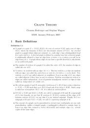
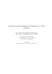
Section 1.5. Linear Polarisation and Refr<strong>ac</strong>tive Index Page 70.03Imaginary part of refr<strong>ac</strong>tive indexrefr<strong>ac</strong>tive index0.0250.020.0150.010.00500 5 10 15 20 25 30 35 40frequencyFigure 1.1: Imaginary part of the refr<strong>ac</strong>tive index versus frequency, ω 0 = 201.015Real part of refr<strong>ac</strong>tive indexrefr<strong>ac</strong>tive index1.011.00510.9950.990.9850 5 10 15 20 25 30 35 40frequencyFigure 1.2: Real part of the refr<strong>ac</strong>tive index versus frequency ω 0 = 20Equations (1.28) and (1.29) are used to solve for the optical coefficients η R and η I associatedwith a specific optical material . Plots of typical values of η I and η R versus frequency are shownin figure 1.1 and 1.2[2].The value of η 1 goes through a maximum at the resonance frequency ω 0 . Since the wavelengthis approximately constant over the region where η 1 has a significant value, it follows that theabsorption coefficient (see Equation (1.22)) also goes through a maximum at ω 0 . This frequencysensitiveabsorption f<strong>ac</strong>tor α suggests that the material absorption is largely dependent on theelectronic char<strong>ac</strong>teristics of the material and how the bound electrons resonate within the material.The plot of η R versus ω in Figure 1.2 is referred to as the dispersion curve. It shows η R graduallyincreasing for increasing ω, passing through a maximum, then decreasing rapidly to a minimum
Section 1.6. Relationship between Energy and Momentum of Photons Page 8as it passes through ω 0 . It then increases again but returns to a lower value than that which ithad before it appro<strong>ac</strong>hed the resonance, and again begins a gradual increase towards the nextresonance. In any region where η R increases with ω, or dη R> 0, the dispersion is referreddωto as normal dispersion. This is because dη R> 0 for most of the infrared, visible, and ultradωspectral regions of most transparent materials. However, in some localised regions where thereis a resonance, dη R< 0, we have a region of anomalous dispersion. In this case the absorptiondωis very high and the electromagnetic radiation is rapidly extinguished[2].A physical interpretation of the refr<strong>ac</strong>tive index can be imagined as follows: the electric field ofthe incident wave polarises the atoms and sets the electrons in a forced sinusoidal motion. The<strong>ac</strong>celeration of the charges radiates a new field that is superimposed on the initial one. Thetwo fields vibrate at the same frequency, however, they are not in phase. When interfering theycreate, inside the material, a field that is not in phase with the incident field. It seems that thelight propagates with a phase velocity that is not equal to c[5].1.6 Relationship between Energy and Momentum of PhotonsSince this Chapter explains the b<strong>ac</strong>kground of this essay, it will necessary for us to remind ourselvesof the relationship between the energy and momentum of a photon. This will help us later inSection 2.2, when we will be discussing how the conservation of energy and momentum in theprocess of the generation of new frequency photons leads to different phase matching conditions.The total energy E and magnitude of momentum for a particle with rest mass m is related byE 2 = ( mc 2)2 + (pc) 2since the photon is massless the energy-momentum relationship for a photon becomesE 2 = (pc) 2 =⇒ E = pc,The energy of an emitted photon is E = ω = hf = h c λ .Consequently the magnitude of the momentum becomesp = k = h λ = hf c .Therefore, the energy and momentum of a photon depends only upon its frequency and consequentlyits wavelength. It is important for us to understand this relation now as it is relevantfor our later discussion of energy and momentum conservation in nonlinear optical effects inChapter 2.1.7 Origin of Nonlinear PolarisationWe had earlier modelled the linear response of the electrons in a medium using the electronoscillation model in Section 1.3, similarly in this Section we will model the nonlinear atomic
Section 1.7. Origin of Nonlinear Polarisation Page 9response of a noncentrosymmetric medium, (that is mediums l<strong>ac</strong>king inversion symmetry) byallowing for nonlinearity in the restoring force exerted on the electrons. In this case, the restoringforce on the electrons is not justF = −Kr,butF = −K 1 r − K 2 r 2 + · · · ,and we have neglected higher order terms. The Equation of motion of an electron then becomes[3]¨r + γṙ + ω0 2 r + r · ã · r = −eE (t) /m, (1.30)where we have introduced a quadratic term, r · ã · r, ã being a third-rank tensor. For the sake ofsimplicity we will only consider only the one dimensional case so that Equation (1.30) can nowbe written as¨r + γṙ + ω 2 0 r + ar2 = −eE (t)/m. (1.31)We obtain this form by assuming that the restoring force is a nonlinear function of the displ<strong>ac</strong>ementof the electron. Considering only the first and second term of the nonlinear expansion ofthe restoring force, we can understand the nature of the force by noting that it corresponds to apotential energy function of the form∫U = − Fdr = 1 2 mω2 0 r2 + 1 3 mar3 . (1.32)Here the first term corresponds to a harmonic potential and the second term corresponds to ananharmonic correction term. This model corresponds to the physical situation of electrons inreal materials, because the <strong>ac</strong>tual potential well that the atomic electron feels is not perfectlyparabolic especially when the applied field is of high intensity[3]. In this case, let us assume thatthe applied optical field is of the formE (t) = E 1 e iω 1t + E 2 e iω 2t + c.c..No general solution to Equation (1.31) exist analytically. However, if the applied field is sufficientlyweak, the nonlinear term ar 2 will be much smaller than the linear term ω 2 0r for any displ<strong>ac</strong>ementr. In order to solve Equation (1.31) we use the idea of perturbation expansion [3]. This meanswe now repl<strong>ac</strong>e E (t) by λE (t) , where λ is a parameter that ranges continuously between zeroand one, and at the end of the calculation will be set equal to one. The expansion parameter λthus char<strong>ac</strong>terises the strength of the perturbation. Equation (1.31) then becomes¨r + γṙ + ω 2 0 r + ar2 = −λeE (t) /m. (1.33)Note here that λ in this Section has nothing to with wavelength, and we just employ this methodbecause we need to solve the Equation (1.31).We now seek a solution to Equation (1.33) in the form of a power series expansion, that isr = λr (1) + λ 2 r (2) + λ 3 r (3) + · · · . (1.34)
Section 1.7. Origin of Nonlinear Polarisation Page 10Using only the first and second term, substituting into Equation (1.33), and equating the coefficientsof the first and second powers of λ, we obtain the following Equations for the coefficientsof λ 1 and λ 2 respectively as¨r (1) + γṙ (1) + ω 2 0 r(1) = −eE (t) /m, (1.35)¨r (2) + γṙ (2) + ω 2 0 r(2) + a [ r (1)] 2= 0. (1.36)Notice that Equation (1.35) is the same as the Equation of motion describing the linear responseof the atoms to the electric field we obtained in Equation (1.6), and we have already found thesolution for this in Equation (1.7). In order to solve Equation (1.36), we choose a solution of theformr (1) (t) = r (1) (ω 1 )e iω 1t + r (1) (ω 2 )e iω 2t + c.c, (1.37)where the amplitudes r (1) (ω j ) have the form (see Equation (1.7))and we have introduced the complex denominator functionE jr (1) (ω j ) = − e m D(ω j ) , (1.38)D(ω) = ω 2 0 − ω 2 − iωγ. (1.39)Squaring Equation (1.37) gives[r (1) (t) ] 2= [ r (1) (ω 1 ) ] 2e−2iω 1 t + 2r (1) (ω 1 )r (1) (ω 2 )e −i(ω 2+ω 1 )t + [ r (1) (ω 2 ) ] 2e−2iω 2 t+ 2r (1) (ω 1 )r (1)∗ (ω 2 )e −i(ω 1−ω 2 )t + 2r (1)∗ (ω 1 )r (1) (ω 2 )e −i(ω 2−ω 1 )t+ 2r (1)∗ (ω 1 )r (1)∗ (ω 2 )e −i(−ω 1−ω 2 )t + [ r (1)∗ (ω 1 ) ] 2e−i(−2ω 1 )t+ 2r (1) (ω 1 )r (1)∗ (ω 1 ) + 2r (1) (ω 2 )r (1)∗ (ω 2 ).Notice that the square of r (1) (t) contains the frequencies ±2ω 1 , ±2ω 2 , ± (ω 1 + ω 2 ), ± (ω 1 − ω 2 )and 0. We see here, and for the first time, the source of the second-harmonic generation. Letus briefly explain this, when we considered the second order term in the nonlinear displ<strong>ac</strong>ementof the electrons by the applied force, and solved the Equation of motion for the electrons, weamongst other frequencies, observed the generation of a frequency doubling that of the frequencyof the incident light (2ω 1 , 2ω 2 ). So, the generation of the second-harmonic frequency is sourcefrom the the nonlinear displ<strong>ac</strong>ement of the electrons and consequently from the susceptibility ofthe material.In order to determine the response of the material at frequency 2ω 1 , for instance, we must solvethe Equationand this implies solving¨r (2) + γṙ (2) + ω 2 0 r(2) = −a [ r (1)] 2, (1.40)[ ] e¨r (2) + γṙ (2) + ω0r 2 (2) 2E1 2 = −ae−2iω 1t. (1.41)m 2 D 2 (ω 1 )
Section 1.7. Origin of Nonlinear Polarisation Page 11We seek a solution of the formr (2) (t) = r (2) (2ω 1 )e −2ω 1t . (1.42)Substituting Equation (1.42) into Equation (1.41) we get that[ ]( )−4ω2 e1 − 2iγω 1 + ω02 r (2) (2ω 1 )e −2ω1t 2E= −a1e 2 −2iωtm 2 D 2 (ω 1 )(1.43)and this implies[ ]er (2) 2E12 (2ω 1 ) = −am 2 D(2ω 1 )D 2 (ω 1 )(1.44)whereD(2ω 1 ) = −4ω 2 1 − 2iω 1γ + ω 2 0 . (1.45)Analogously, the amplitudes of the response at frequency 2ω 2 is found to be[ ]er (2) 2E12 (2ω 2 ) = −a. (1.46)m 2 D(2ω 2) D 2 (ω 1 )The linear contribution to polarisation from Equation (1.1) is given in a more general form byP (1) (ω 1 ) = −Ner (1) (ω j )then using Equation (1.38), we can now write P (1) (ω 1 ) asP (1) (ω 1 ) = Ne2 E jmD(ω j ) , (1.47)From Equation (1.47), we define the linear susceptibility in general asχ (1) (ω i ) =Ne2mD(ω j ) .The linear polarisation in a more general form is defined byP (1) (ω 1 ) = χ (1) (ω j )E(ω i ). (1.48)The nonlinear polarisation and susceptibilities are calculated in an analogous manner. The nonlinearsusceptibility describing second-harmonic generation χ (2) is defined by the relationHere ,P (2) (2ω 1 ) = χ (2) (2ω 1 , ω 1 , ω 1 )E(ω 1 ) 2 . (1.49)χ (2) (2ω 1 , ω 1 , ω 1 ) = N(e3 /m 2 )aD(2ω 1 )D 2 (ω 1 )(1.50)and P (2) (2ω 1 ) is the nonlinear polarisation source for the second-harmonic generation.
Section 1.7. Origin of Nonlinear Polarisation Page 12From Equation (1.49), we see that the nonlinear polarisation source for the second-harmionicgeneration depends on the square of the incident electric field. In order to maximise this, theapplied electric field must have a high intensity. That is why the invention of lasers with highintensity light brought to the fore, the nonlinear optical effects in materials. Also, the nonlinearpolarisation source for the second-harmonic generation depends on the nonlinear susceptibilityχ (2) (2ω 1 , ω 1 , ω 1 ) expressed in Equation (1.50), in the denominator of this susceptibility, we seefrom Equation (1.39) and (1.45), that the second order nonlinear susceptibility (χ (2) (2ω 1 , ω 1 , ω 1 )may be resonantly enhanced at the frequencies (ω 0 ≈ ω 1 and ω 0 ≈ 2ω 1 ). In resonant enhancementprocesses the frequency of the lasers is tuned, so that it is close to the resonant frequencyof the material. This helps to increase the susceptibility.This Section helps to to understand that if we consider the application of an intense electric fieldto a medium, the expression for a linear polarisation obtained in Equation (1.11) does not hold.From the electron model we would say that the displ<strong>ac</strong>ement r of the electrons is no longer smallsince the field is intense and so we must consider at least the quadratic term in the nonlinearexpansion of the elastic restoring force. Doing this, we discovered the polarisation of a nonlinearmedium can even be expressed as a power series and this leads us to Chapter 2 where we willlook at the different second order nonlinear optical effects.
2. <strong>Second</strong> Order Nonlinear OpticalPhenomena2.1 Nonlinear PolarisationThe linear polarisation P of a material depends upon the strength of the applied field asP = ɛ 0 χ (1) E. (2.1)Where χ (1) is the linear electric susceptibility, a useful parameter when considering the responseof an material to applied electric field. In nonlinear optics, where the electric field strength ishigh enough, Equation (2.1) can then be generalised by expressing it as a power seriesP = ɛ 0(χ (1) E + χ (2) E 2 + χ (3) E 3 + · · ·).(2.2)The polarisation effect makes a significant contribution to the nonlinear optical process since itresults from charges oscillating within the medium due to the incident oscillating electric field andre-radiating, thereby adding to that field. For simplicity, we have expressed P and E as scalarquantities. Also since Equation (2.2) is time dependent, we have assumed that the response ofthe material is instantaneous to the applied field. For this assumption to be true, the mediummust have no loss or dispersion [2].2.1.1 Nonlinear Wave EquationWe had earlier derived the wave equation of a dielectric medium in Equation 1.15, we nowuse Maxwell’s Equations to derive the nonlinear wave Equation, this Equation shows that thenonlinear polarisation source is frequency dependent. We consider the time-spatial variation ofan optical field <strong>ac</strong>cording to Maxwell’s Equation∂E∇ × H = ɛ 0∂t + ∂P∂t(2.3)and∂H∇ × E = −µ 0∂t . (2.4)In general, E, P and H may be arbitrary time-spatial functions that can be expressed in Fourierintegral form [6]:E(t, r) =∫ ∞−∞E(ω, r)e −iωt dω,H(t, r) =∫ ∞−∞H(ω, r)e −iωt dω,13
Section 2.1. Nonlinear Polarisation Page 14andP(t, r) =∫ ∞−∞P(ω, r)e −iωt dω.Here, r represents the spatial variables. The physical meaning of these expressions is that anygiven optical field can always be viewed as a certain superposition of infinite monochromaticFourier components[6].Now, for a given function f(t), the Fourier transform of its derivative f ′ (t) is given byF(f ′ (t)) =∫ ∞−∞f ′ (t)e iωt dt= e iωt f(t) − iω∫ ∞−∞e iω f(t)= −iωf(ω). (2.5)Here f(t) tends to zero at ± ∞ (as it must since ∫ ∞|f(t)|dt must be finite [7]). So taking the−∞derivative of the Fourier transforms in Equation (2.1.1), we get that∫ ∞−∞∂E(t, r)e iωt dt = −iωE(ω, r),∂tand∫ ∞−∞∫ ∞−∞∂H(t, r)e iωt dt = −iωH(ω, r),∂tWith these transformations Equation (2.3) becomes∂P(t, r)e iωt dt = −iωP(ω, r). (2.6)∂t∇ × H(ω, r) = −ɛ 0 iωE(t, r) − iωP L (ω, r) − iωP NL , (2.7)where we have expressed the polarisation P in terms of its linear term P L and nonlinear termP NL . We have also assumed thatSimilarly Equation (2.4) becomesP(ω, r) = P L (ω, r) + P NL (ω, r).Taking the curl of Equation (2.8) and using (2.7), we get∇ × E(ω, r) = µ 0 iωH(ω, r). (2.8)∇ × (∇ × E(ω, r)) = µ 0 ɛ 0 ω 2 E(ω, r) + µ 0 ω 2 [ P L (ω, r) + P NL (ω, r) ] . (2.9)
Section 2.2. <strong>Second</strong> Order Nonlinear Optical Processes Page 15Considering thatandP L (ω, r) = ɛ 0 χ (1) (ω)E(ω, r) (2.10)ɛ(ω) = ɛ 0[1 + χ (1) (ω) ] , (2.11)where ɛ(ω) is the linear dielectric constant at frequency ω, Equation (2.9) can then be written as∇ × (∇ × E(ω, r)) − µ 0 ɛ 0 ω 2 ɛ(ω)E(ω, r) = µ 0 ω 2 P NL (ω, r). (2.12)Equation (2.12) is the fundamental Equation for E(ω, r) and P NL (ω, r) and is called the nonlinearwave Equation. So for a weak incident optical field P NL (ω, r) ≈ 0, Equation (2.12) becomes thelinear wave Equation∇ × (∇ × E(ω, r)) − µ 0 ɛ 0 ω 2 ɛ(ω)E(ω, r) = 0. (2.13)In this case, the polarisation response of a material to a given monochromatic component E(ω, r)of the applied field is only represented by the dielectric constant ɛ(ω); the other frequency componentsof the field have no influence on either P L (ω, r) or E(ω, r). Whereas, if the applied fieldis an intense laser field, the second and/or third order components expressed by Equation (2.2)may no longer be neglected. Then Equation (2.12) becomes a nonlinear differential Equation,and the term P NL (ω, r) can be recognised as a source that can emit coherent radiation at a newfrequency[6].2.2 <strong>Second</strong> Order Nonlinear Optical Processes2.2.1 <strong>Second</strong>-<strong>Harmonic</strong> <strong>Generation</strong>We now know that with an intense laser field, the polarisation of the material is a nonlinearfunction of the electric field, so what happens in second harmonic generation is that, an intenselaser beam of angular frequency ω is passed through a crystal with nonzero value of χ (2) , suchthat the beam emerging from the crystal contains the the angular frequencies ω of the input beamand also 2ω, twice the frequency of the input beam. This can be shown to occur by consideringthe second order nonlinear polarisation term (2.2). Let us consider the case in which two inputphotons have different frequencies ω 1 and ω 2 , where ω 1 > ω 2 .E = E 1 e −iω 1t + E ∗ 1 eiω 1t + E 2 e −iω 2t + E ∗ 2 eiω 2t . (2.14)We consider the second order nonlinear polari<strong>za</strong>bility asP (2) = ɛ 0 χ (2) E 2= ɛ 0 χ (2) [E 2 1 e−i(2ω 1)t + (E ∗ 1 )2 e i(2ω 1)t + E 2 2 e−i(2ω 2)t + (E ∗ 2 )2 e i(2ω 2)t+2E 1 E ∗ 1 + 2E 2E ∗ 2 + 2E 1E 2 e −i(ω 1+ω 2 )t + 2E ∗ 1 E∗ 2 ei(ω 1+ω 2 )t+2E 1 E ∗ 2e −i(ω 1−ω 2 )t + 2E ∗ 1E 2 e i(ω 1−ω 2 )t ].
Section 2.2. <strong>Second</strong> Order Nonlinear Optical Processes Page 16The result includes the second-harmonic terms with 2ω 1 and 2ω 2 . The direct current termsrepresents a time independent f<strong>ac</strong>tor that produces no oscillating electromagnetic radiation. Thesum-frequency generation is the addition of the two fundamental frequencies ω 1 + ω 2 and thedifference frequency generation ω 1 − ω 2 .Let us look at this different optical frequency mixing effects from a quantum theory of radiationstand point. The advantage of considering the quantum theory of radiation is that it not onlydescribes the wave property of the optical field but also involves transfer of energy and momentum.Before we go into describing how the second order nonlinear optical effects can be describedfrom the quantum mechanical stand point, it is pertinent to recall how the quantum theory ofradiation works.An inter<strong>ac</strong>tion between an optical field and a medium is always <strong>ac</strong>companied by1. a quantum transition of molecules of the medium among their different states.2. a change of photon distribution. In order to properly describe this process we must introducethe key concept of the so-called intermediate state.In this intermediate state of the whole system, the degener<strong>ac</strong>y among the different modes ischanged while the molecules have left their original state which is usually the ground state. Atthis point we cannot say ex<strong>ac</strong>tly which excited state a molecule is, but we can distribute the stateof a molecule to all possible excited states with a certain distribution probability. In this case, it isconvenient to introduce a virtual state in the energy level diagram to represent this intermediatestate. Based on the concept of intermediate state, as well as a representation of a virtual energylevel, we can now explain the second order nonlinear optical effects.In the case of the second harmonic-generation, two photons of frequency ω leaves the groundstate to an intermediate, while returning to its initial state there is an emission of a secondharmonic photon. As shown in the diagram below [6].Intermediate statehfhf2hfGround stateFigure 2.1: Energy level description of second harmonic generation from a quantum standpoint.In Figure 2.1, h is the Planck constant and f is the frequency of the photon.Since the transit time of the molecules in the intermediate state is extremely short about 10 −16 s,the above processes occur simultaneously and instantaneously[3]. One can find that at thebeginning and end of this process, the quantum states of this processes are unchanged (the
Section 2.2. <strong>Second</strong> Order Nonlinear Optical Processes Page 17energy and momentum of the molecules are unchanged) therefore the conservation of energy andmomentum should hold among the annihilated photons and created photon(s).Assuming the frequencies of the fundamental and second-harmonic waves are f 1 and f 2 respectively,then conservation of energy and momentum gives us thatandhf 2 = 2hf 1 , (2.15)k 2 = k 1 + k 1 . (2.16)Here k 1 and k 2 are the wave vectors of these two waves and h is Planck’s constant. FromEquation (2.16) we obtain that2π= 2 · 2πλ 2 λ 1=⇒ 2πf 2v 2= 2 · 2πf 1v 1(2.17)where v is the corresponding speed of the waves, and this implies thatω 2c η(f 2) = 2 ω 1c η(f 1), (2.18)where η(f 1 ) and η(f 2 ) are the refr<strong>ac</strong>tive indices of the medium at the frequencies f 1 and f 2respectively.From Equation (2.15), we know that 2ω 1 = ω 2 , hence Equation (2.18) leads to the so calledphase matching conditionη(2f 1 ) = η(f 1 ). (2.19)So we see that the phase-matching condition which we will further explain in Section 3.2, is anatural result of the conservation of energy and momentum from the stand-point of quantumtheory of radiation.2.2.2 Optical Sum Frequency <strong>Generation</strong>Within the same framework we will look at the sum-frequency generation from the quantummechanical point of view. In this case the elementary process is composed of two steps, in thefirst step, two photons one from ω 1 and the other from ω 2 is simultaneously annihilated as amolecule leaves its ground state to an intermediate state. On returning, one photon is createdand added to the ω 3 field. The energy level diagram for sum-frequency generation is shown inFigure 2.2There should be conservation of energy and momentum at the beginning and end of the process,so we then havehf 3 = hf 1 + hf 2 , (2.20)
Section 2.2. <strong>Second</strong> Order Nonlinear Optical Processes Page 18Intermediate statehf 2hf 1hf 3Ground stateFigure 2.2: Energy level description of sum-frequency generation from a quantum standpoint.andk 3 = k 1 + k 2 , (2.21)where k 1 , k 2 and k 3 are the wave vectors of the these three waves. From Equation (2.21), wesee that the phase matching condition requires thatand this implies thatω 3c η(f 3) = ω 1c η(f 1) + ω 2c η(f 2), (2.22)ω 3 η(f 3 ) = ω 1 η(f 1 ) + ω 2 η(f 2 ).2.2.3 Optical Difference-Frequency <strong>Generation</strong>Using the same assumption that the incident optical field contains two frequency components ω 1and ω 2 and ω 1 > ω 2 a new radiation wave at the frequency ω 3 = ω 1 −ω 2 can be generated and isexplained from the quantum point that, there is an annihilation of one high frequency photon asa photon leaves its ground state to an intermediate state and simultaneously there is the creationof two lower frequencies (hf 2 and hf 3 ) photons when the molecule is returning to its groundstate.Intermediate statehf 1hf 2hf 3Ground stateFigure 2.3: Energy level description of difference-frequency generation form a quantum standpoint.
Section 2.2. <strong>Second</strong> Order Nonlinear Optical Processes Page 19In a similar way, as the other two frequency conversions, there must be conservation of energyand momentum in these processes so,andhf 1 = hf 2 + hf 3 ,k 1 = k 2 + k 3 .These Equations leads to the phase matching condition ofω 1c η(f 1) = ω 2c η(f 2) + ω 3c η(f 3).which implies thatω 1 η(f 1 ) = ω 2 η(f 2 ) + ω 3 η(f 3 ).2.2.4 Nonlinear Crystals for <strong>Second</strong>-harmonic generationThere are some basic requirements for nonlinear crystals to support second-harmonic generation.We will briefly discuss some of these,1. Noncentrosymmetry: In the electric dipole approximation for nonlinear media describedin Section 1.7, isotropic media and centrosymmetric crystals cannot be used to generatesecond order nonlinear effects . Therefore, the media for second-harmonic generation shouldbe the crystals l<strong>ac</strong>king symmetry inversion such that U(−x) = U(x) and the potentialenergy is of the form so, for centrosymmetric media the potential energy should be of theformU = 1 2 mω2 0 x2 − 1 4 mbx4 + · · · . (2.23)So we see that for a centrosymmetric media the term ar 2 in Equation (1.31) is repl<strong>ac</strong>edby a nonlinear term br 3 and the second order nonlinear susceptibility vanishes.2. Phase-matching: We have proved theoretically that only when the phase matching conditionof η(2f 1 ) = η(f 1 ) is <strong>ac</strong>hieved can the second-harmonic generation be efficiently obtained.For a normal dispersion (see Section 1.5), η(2f 1 ) is greater than η(f 1 ) and we have tochoose a special direction within a given crystal so that the dispersion effect of refr<strong>ac</strong>tiveindex is compensated by the birefringence effect(see Section 3.2.1). The angle betweenthis special direction and the optical axis of the crystal is termed the phase matching angle.phase matching angle is explained further in Section 3.2.2.3. Larger effective second-order susceptibility value: Since the efficiency of the second-harmonicgeneration is proportional to the square of the effective second order susceptibility valueχ (2) , so crystals with a larger value of χ (2) are preferred. This dependence is seen fromEquation (3.15) and (3.30).4. High optical damage threshold: To ensure a higher and incident optical power, all crystals forsecond-harmonic generation should possess the best optical quality and high transmittivityfor both the fundamental and second harmonic waves.
3. <strong>Second</strong>-<strong>Harmonic</strong> <strong>Generation</strong>In this Chapter we try to solve using Maxwell’s Equation for the intensity of the second harmonicwave and explain the ideal ways of obtaining an efficient second-harmonic generation.3.1 Intensity of a <strong>Second</strong>-<strong>Harmonic</strong> WaveFrom Maxwell’s Equations, we see that the wave Equation (see Equation (1.17)) for a nonconducting medium is∇ 2 ∂ 2 EE − ɛ 0µ0∂t = µ ∂ 2 P2 0∂t . (3.1)2We can then deduce that the second-harmonic term in the polarsation P should generate a secondharmoniccontribution to the electric field E. This means that an electric field of frequency ωin a non-centrosymmetric medium, will through the nonlinear polarisation P NL (2ω) generate anelectric field at the second-harmonic frequency 2ω. Let us try to derive the intensity of the electricfield at the second-harmonic. We write the second harmonic field asE = 1 2[E2ω (z)e −i(2ωt−k 2ωz) + E ∗ 2ω (z)ei(2ωt−k 2ωz) ] , (3.2)where k 2ω = 2ωη(2ω) and η(2ω) = (ɛ c 2ω/ɛ 0 ) 2 is the refr<strong>ac</strong>tive index of the medium for radiationof frequency 2ω. The wave Equation for the second-harmonic generation can then be derived.First the first term in the left hand side of Equation (3.1) becomes∇ 2 E 2ω = 1 2[( d 2 E 2ωdz 2+ ik 2ωdE 2ωdz)+ ik 2ω(dE2ωdz − k2 2ωE 2ω)]e −i(2ωt−k 2ωz) + c.c.. (3.3)Assuming the amplitude E 2ω to be slowly varying in z we make an approximation by neglectingsecond derivatives of E 2ω , to get∇ 2 E 2ω = 1 ()dE 2ω2ik 2ω2 dz − k2 2ωE 2ω + c.c , (3.4)which together withgives the left side of Equation (3.1) as∇ 2 E 2ω − ɛ 0 µ 0∂ 2 E 2ω∂t 2ɛ 0 µ 0∂ 2 E 2ω∂t 2 = −2ɛ 0 µ 0 ω 2 [ E 2ω e −i(2ωt−k 2ωz) + c.c ] , (3.5)≈(dE 2ωik 2ωdz − 1 (k22 2ω − 4ɛ 0 µ 0 ω 2) )E 2ω e −i(2ωt−k2ωz) + c.c (3.6)20
Section 3.1. Intensity of a <strong>Second</strong>-<strong>Harmonic</strong> Wave Page 21For the second-harmonic field Equation in (3.2), the right side of Equation (3.1) has both linear(L) and nonlinear (NL) contributions at frequency 2ω:andP = 1 (L)[P 2ω (z)e i(2ωt−k2ωz) + P (L)∗2ω (z)e i(2ωt−k 2ωz)2+ P (NL)2ω (z)e 2i(ωt−kωz) + P (NL)∗2ω (z)e 2i(ωt−kωz) ] (3.7)µ 0∂ 2 P∂t 2= −2µ 0 ω 2 [P (L)2ω (z)e i(2ωt−k 2ωz) + P (L)∗2ω (z)e i(2ωt−k 2ωz) ]−2µ 0 ω 2 [P (NL)2ω (z)e 2i(ωt−kωz) + P (NL)∗2ω (z)e 2i(ωt−kωz) ]. (3.8)Combining the real parts of Equations (3.6) and (3.8), we get(dE 2ωik 2ωdz − 1 (k22 2ω − 4ɛ 0 µ 0 ω 2) )E 2ω e −i(2ωt−k 2ωz)= −2µ 0 ω 2 P L 2ω (z)ei(2ωt−k 2ωz) − 2µ 0 ω 2 P NL2ω (z)e2i(ωt−kωz) . (3.9)We know that P = ɛ 0 χE, which at a frequency of 2ω becomesandP (L)2ω = ɛ 0 χ(2ω)E 2ω (3.10)k 2 2ω = (2ω)2 ɛ 2ω µ 0 = 4ω 2 ɛ 0 µ 0 η 2 (2ω) = 4ω 2 ɛ 0 µ 0 [1 + χ(2ω)],see Equation (2.11) (3.11)We have also used the relation; speed of light in v<strong>ac</strong>uum c = 1 √µ0 ɛ 0and the speed of light in amedium at frequency 2ω is v 2ω =1√ɛ2ω µ 0.We have taken χ 2ω to be real because we are assuming absorption and other loss processes tobe negligible. The use of these relations in Equations (3.9) results in the Equationorik 2ωdE 2ωdz ei(2ωt−k 2ωz) = −2µ 0 ω 2 P NL2ω (z)e2i(ωt−kωz) , (3.12)dE 2ωdz= 2iµ 0ω 2k 2ωP (NL)2ω e i(2ωt−k 2ωz−2ωt+2k ωz)= iω √ µ 0 /ɛ 2ω P (NL)2ω e i(2kω−k 2ω)z,(3.13)and this relates the second-harmonic field to the nonlinear polarisation. Finally it is convenientto define a quantityP (NL)2ω = dEω 2 (z), (3.14)
Section 3.1. Intensity of a <strong>Second</strong>-<strong>Harmonic</strong> Wave Page 22where d represents (see Equation (1.49))d = ɛ 0 χ (2) (2ω, ω, ω). (3.15)Thus we can write Equation (3.13) asdE 2ωdz= = iω√µ0ɛ 2ωdE 2 ω (z)ei∆kz , (3.16)where∆k = 2k ω − k 2ω = 2ω √ ɛ 0 µ 0 [η(ω) − η(2ω)]. (3.17)The solution to Equation (3.16) gives the second-harmonic field amplitude E 2ω (z). In other tosolve the Equation, we need to know E ω (z). To simplify our work, we make the approximationthat there is little attenuation of the fundamental wave so that E ω is a constantE ω (z) ≈ E ω (0). (3.18)This approximation is often called small signal limit. Within this approximation, the signal of thesecond-harmonic wave generated is still small. In pr<strong>ac</strong>tice as the conversion from a fundamentalto a second harmonic wave continues in the medium, there is depletion of the fundamental waveand this approximation is no longer a good one.With this approximation (3.16) can be integrated to obtain√ ∫ z µ0E 2ω (z) ≈ iω dEω 2 ɛ (0) e i∆kz dz2ωNow 1i∆k (ei∆kz − 1) can be written asEquation (3.21) becomes0(3.19)√ ( )µ0 1= iω dEω 2 ɛ (0) 2ω i∆k (ei∆kz − 1) . (3.20)1i∆k (ei∆kz − 1) = ei∆kz/2i∆k (ei∆kz/2 − e −i∆kz/2 ). (3.21)1i∆k (ei∆kz − 1) = 2e i∆kz/2 1∆k sin1 2 ∆kz (3.22)( sin1= ze i∆kz/2 ∆kz )21∆kz . (3.23)2So with the approximation that the fundamental wave is unattenuated we have√ (µ0sin1E 2ω (z) = iω dEω 2 ∆kz )ɛ (0)zei∆kz/2 212ω ∆kz . (3.24)2
Section 3.1. Intensity of a <strong>Second</strong>-<strong>Harmonic</strong> Wave Page 23Equation (3.24) describes the amplitude of the second harmonic wave, under the approximationthat the applied field is not attenuated inside the medium.Suppose the nonlinear crystal is of length L as in Figure (2.3) . The second harmonic field atthe exit f<strong>ac</strong>e of the crystal is then given by Equation (3.23) with z = L. Thus Equation (3.24)implies that|E 2ω (L)| 2 = µ (0ω 2 (sin1|E ω (0)| 4 L 2 )∆kL )21ɛ 2ω ∆kL . (3.25)2The intensities of the fields at ω and 2ω as given by Equation (1.22) areI ω = 1 √ɛω|E ω | 2 , (3.26)2 µ 0It follows from (3.25) thatI 2ω = 1 2√ɛ2ωµ 0|E 2ω | 2 . (3.27)I 2ω (L) = 2µ3/2 0 d 2 ω 2√ |E ω (0)| 41 ( sin1ɛ ω ɛ2ω 4 ɛ ω/µ 0 L 2 ∆kL ) 221∆kL 2(= 2µ3/2 0 d 2 ω 2 sin1√ I 2ɛ ω ɛ2ωω(0)L 2 ∆kL ) 221∆kL 2( ) 3/2 µ0 ω 2 d 2= 2ɛ 0( sin1∆kLη 2 (ω)η(2ω) I2 ω (0)L2 2) 21∆kL . (3.28)2This Equation gives the intensity of the second-harmonic wave under the approximation that thefundamental wave is unattenuated in the medium, and as expected, the intensity of the secondharmonic wave is seen to increase as the square of the fundamental wave. Since the phasevelocities of the fundamental and second-harmonic wave is different, the second-harmonic wavedo not receive enough energy from the fundamental wave so the approximation that the wave isunattenuated is fair at this point.From this we can now obtain the power conversion efficiency for second-harmonic generation,C SHG asC SHG= I 2ω(L)(3.29)I ω (0)( ) 3/2 (µ0 ω 2 d 2 sin1= 2ɛ 0 η 2 (ω)η(2ω) I ω(0)L 2 ∆kL ) 221∆kL . (3.30)2
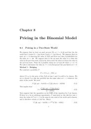
Section 3.1. Intensity of a <strong>Second</strong>-<strong>Harmonic</strong> Wave Page 24We see in Equation (3.30) that the conversion efficiency of the second-harmonic generation ismaximised when ∆k = 0 or when L is very small. This leads to the phase matching of making∆k = 0. When phase matching is <strong>ac</strong>hieved, the conversion efficiency of the second-harmonicgeneration increases, in order words, there is transfer of energy from the fundamental to thesecond-harmonic wave and we can no longer neglect the depletion of the fundamental wave.As a result of this depletion, the second-harmonic generation re<strong>ac</strong>hes a saturation point whereit maintains a constant value, this occurs because the source of its energy which is from thefundamental wave is depleted.In an experiment, using BB0 (barium borate) as the nonlinear crystal for generating a secondharmonicsignal, the relation between the average input power and the generated second-harmonicsignal is illustrated in Figure 3.1. In this experiment there was phase matching. A quadraticpolynomial was fitted into the data for the input power versus the second-harmonic signal, thefitting on the curve showed that for small signals the the intensity of the second-harmonic waveincreases quadratically as the fundamental or pump wave. This experimental result confirmes ourtheoretical calculations as expressed in equation (3.28).120fitted quadratic polynomial100second-harmonic signal(a.u.)806040200-200 50 100 150 200average input power(mW)Figure 3.1: Intensity of the second-harmonic signal versus the average input powerHowever, in cases where the length of the crystal is small we do not bother about phase matchingbecause length of the crystal is within the coherence length. We will discuss the coherence lengthin section 3.2. When η(ω)=η(2ω), this means there is phase matching (∆k = 0) as in Equation(3.17), andsin 2 xlim = 1 =⇒x→0 x 2( sin12 ∆kL12 ∆kL ) 2= 1. (3.31)
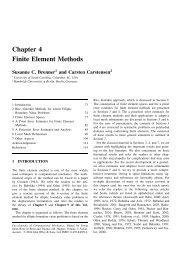
Section 3.2. Phase Matching Condition Page 25Thus in this case, the conversion efficiencyfor η = η(ω) = η(2ω).( ) 3/2 µ0 ω 2 d 2C SHG = 2ɛ 0 η I ω(0)L 2 , (3.32)3laserωnonlinearcrystal2ω2ωphotocellωFigure 3.2: Schematic experimental arrangement for detection of second-harmonic generation,where ω is the frequency of the incident laser beam.filter3.2 Phase Matching ConditionPhase matching is an important aspect of second-harmonic generation and nonlinear optics ingeneral. The phenomenon of phase matching in relation to second harmonic generation can beexplained thus:the f<strong>ac</strong>tor ∆kL in Equation (3.28) determines the phase mismatch f<strong>ac</strong>tor e (2ikωz−ik 2ωz) (as expressedin Equation (3.13)) between the fundamental and second harmonic waves over the distancez = L. This is as a result of the different refr<strong>ac</strong>tive indexes for the two waves.The reason for the phase mismatch ∆kL between the fundamental(pump) and second harmonicfields can be explained as described below: the second-harmonic field propagates with the phasecvelocity , but we can see that from Equation (3.7) the nonlinear polarisation source hasη(2ω)ca phase velocity . Because of this difference the two fields get out of step of e<strong>ac</strong>h other.η(ω)Since the medium will only allow the second-harmonic field to propagate at a phase velocity of, there is a reduction in the second-harmonic generation determined by η(2ω) − η(ω), andcη(2ω)(sin12 ∆kL1) 2.this reduction is expressed quantitatively by the f<strong>ac</strong>tor Taking a range of values2 ∆kL−2π ≤ 1 ∆kL ≤ −2π (see Appendix B.1 for code), the function2was plotted as shown in Figure 3.3.f(L) =( sin1∆kL ) 221∆kL 2
Section 3.2. Phase Matching Condition Page 261f(L)L c0.80.6f(L)0.40.20-8 -6 -4 -2 0 2 4 6 81∆kL 2Figure 3.3: The graph of f(L) = (sin2 αL), where α ≡ ∆k/2.(αL) 2The function drops to about 40 percent of its peak value at the distance12 ∆kL = π 2 ,or∆kL = π.Therefore, we define the coherence length L c , such that∆kL c = π,orL c = | π ∆k |.The coherence length is a certain fr<strong>ac</strong>tion of L over which there is a significant second-harmonicgeneration. If there is a perfect phase matching then L C is large, that is ∆k −→ 0. Theconversion efficiency C SHG as expressed in Equation (3.30), increases as the square of the lengthL. When phase matching is not <strong>ac</strong>hieved, however, only the coherence length L c determinesthe conversion efficiency. If phase matching is not <strong>ac</strong>hieved, increasing L beyond L c does notincrease the conversion efficiency because the coherence length is usually very small on the orderof 10µm[4].Phase matching can be <strong>ac</strong>hieved in different ways, That is, making |∆k| small as possible.One common method involves using birefringent uniaxial crystals to phase match the incidentand second harmonic field. We would briefly discuss what a birefringent material is so that weunderstand why it is useful in phase matching.
Section 3.2. Phase Matching Condition Page 273.2.1 BirefringenceLet us discuss the birefringent nature of anisotropic materials as this will help us understand howand why they are used for phase matching. We have assumed that the elastic force <strong>ac</strong>ting on abound electron is independent of the electron displ<strong>ac</strong>ement r. In general, however, “the springconstant” k may depend on the direction of r, in which case the medium is said to be opticallyanisotropic. In such a medium the refr<strong>ac</strong>tive index will be different for different polarisation ofthe field propagating through the medium. This is called birefringence [4].We can understand how anisotropy may arise when we consider a long rod-shaped molecule inwhich the elastic restoring force is different for electron displ<strong>ac</strong>ement parallel and perpendicularto any axis of the molecule. There will be different refr<strong>ac</strong>tive indices for different direction of fieldpolarisation in a medium in which there is some degree of molecular alignment. Most birefringentmaterials are uniaxial in the sense that they have one optical axis. An optical axis is one in whichthe refr<strong>ac</strong>tive index is independent of the direction of the polarisation of the medium.3.2.2 Angle Phase Matching MethodThe method involves <strong>ac</strong>hieving a particular orientation of a birefringent crystal with respect tothe propagation direction of the incident light. This method is most easily described if the crystalis uniaxial, that is, if it has only one optical axis, so we will consider the case where the crystalis uniaxial. Only two types of waves can propagate in a birefringent uniaxial crystal namely:1. Waves that are polarised in a direction that is perpendicular to the plane of the optical axisĉ of the crystal and the direction of propagation k. Such waves are called ordinary wavesand their refr<strong>ac</strong>tive index η o is called ordinary refr<strong>ac</strong>tive index.2. Waves polarised in a direction parallel to the plane of the optical axis and the directionof propagation. The waves are called extraordinary waves and their refr<strong>ac</strong>tive index η e (θ)which depends on the angle θ between the optic axis and the propagation vector k, is calledextraordinary refr<strong>ac</strong>tive index,The extraordinary wave with η e (θ) depends upon the angle θ between the optic axis and k bythe relation[3]1ηe 2(θ, ω) = sin2 θη e2 (ω) + cos2 θ(3.33)(ω).Here, η e (ω) is the value of η e (θ, ω) for θ = 90 degrees and is equal to η o for θ = 0. The angulardependence of the extraordinary ray expressed in Equation (3.33) is as a result of the geometryof the nonlinear crystal, for this work we will not look at its derivation.Phase matching is <strong>ac</strong>hieved by adjusting the angle θ to <strong>ac</strong>hieve a value of η e (θ, ω) for which thecondition ∆k = 0 is satisfied.η 2 o
Section 3.2. Phase Matching Condition Page 28Let us consider obtaining a second-harmonic generation in a positive uniaxial crystal, a uniaxialcrystal is said to be positive ifη e (ω) > η 0 (ω).ωordinaryθĉk2ωextraordinaryFigure 3.4: Geometry for angle phase matching of second-harmonic generation.So in order to phase match the fundamental and second-harmonic wave, we choose the fundamentalwave to be an extraordinary wave and the second-harmonic to be an ordinary wave,so that the birefringence of the material can compensate for the dispersion, that is the directdependence of refr<strong>ac</strong>tive index on the frequency of the waves. We have said that the refr<strong>ac</strong>tiveindex of the extraordinary wave depends on the angle θ between the propagation vector k andthe optical axis ĉ, phase matching is then <strong>ac</strong>hieved if the angle θ p is chosen such thatand this implies thatη 0 (2ω) = η e (ω, θ p ), (3.34)1η 2 e (θ p, ω) = 1η 2 0 (2ω) = cos2 θ pη 2 o (ω) + sin2 θ pη e2 (ω)1η 2 0(2ω) − 1η 2 0(ω)= 1 − sin2 θ pη 2 o (ω)+ sin2 θ pη e2 (ω)= − sin 2 θ p( 1η 2 0(ω) − 1η 2 e(ω)− 1η 2 0 (2ω) + 1η 2 0 (ω) = sin 2 θ p( 1η 2 0 (ω) − 1η 2 e (ω) ),)(3.35)so solving for sin 2 θ p , we havesin 2 θ p = η 0(ω) −2 − η 0 (2ω) −2. (3.36)η 0 (ω) −2 − η e (ω)−2This Equation shows how the crystal should be orientated in order to <strong>ac</strong>hieve phase matchingcondition. Assuming the crystal to be normally dispersive, that is η 0 (2ω) > η 0 (ω), implies thatη 0 (ω) −2 − η 0 (2ω) −2 > 0,
Section 3.2. Phase Matching Condition Page 29so we can deduce thatη e (ω) > η 0is necessary to satisfy the requirement that sin 2 θ p > 0. Note that if sin 2 θ p = 0, then θ p = 0 andwe do not want θ p = 0, else η e (ω) = η 0 and this will not help since we are considering a positiveuniaxial crystal to help phase match the pump and the second-harmonic wave. Also we see thatη 0 (ω) −2 − η 0 (2ω) −2 < η 0 (ω) −2 − η e (ω) −2 which impliesη e (ω) > η 0 (2ω) (3.37)is necessary for sin 2 θ p < 1, meaning that θ p is less than 90 degrees for a positive uniaxial crystal.So we can conclude that, this method of phase matching is used in a positive uniaxial crystalwhen the condition in Equation (3.37) has been met, since η 0 (2ω) > η 0 (ω) and Equation (3.37)both imply that η e (ω) > η 0 (ω).In pr<strong>ac</strong>tice the pump or fundamental wave is sent into the crystal as an extraordinary wave atthe angle θ p with respect to the optical axis and the second harmonic wave is automaticallygenerated as an ordinary wave propagating in propagating in the direction θ p , because this is theonly direction and polarisation for which there is phase matching and substantial second-harmonicgeneration [4].For a negative uniaxial crystal the situation is reversed, phase matching is <strong>ac</strong>hieved if θ p is chosensuch thatη e (2ω, θ p ) = η 0 (ω).We chose the fundamental wave to be an ordinary wave and the second harmonic wave to be anextraordinary wave. The angle between the pump and fundamental wave is derived in a similarmanner as in Equation (3.33)1ηe 2(θ p, 2ω) = cos2 θ pη0(2ω) + sin2 θ p(3.38)2 (2ω),η 2 eSolving for sin 2 θ pand this can be written assin 2 θ p = η 0(2ω) −2 − η 0 (ω) −2η 0 (2ω) −2 − η e (2ω) −2,Sincesin 2 θ p = η 0(ω) −2 − η 0 (2ω) −2η e (2ω) −2 − η 0 (2ω)−2.(3.39)η 0 (ω) −2 − η 0 (2ω) −2 < η e (2ω) −2 − η 0 (2ω) −2 ,is required, then phase matching may be <strong>ac</strong>hieved ifη e (2ω) < η o (ω)(negative uniaxial). (3.40)
4. ConclusionUsing the electron oscillation model, the linear and nonlinear response of an electron to an appliedoptical field was modelled. The nonlinear response of the electrons to the applied force showedthat the polarisation of a material can be expressed as a power series in the applied electric field,such that for light with high intensities such as laser light, frequencies, doubling that of theincident light can be obtained. As a result of this, we solved Maxwell’s equation and observeda nonlinear source term P NL (ω) that could generate coherent radiation at a new frequency. Sotreating the case of second-harmonic generation, we considered the nonlinear polarisation sourceof P(2ω) that could generate an electric field propagating at the frequency 2ω. The followingdeductions were made on the efficiency of the generation of a second-harmonic generation:1. The intensity of the second-harmonic signal depends on the square of the incident laser lightunder the approximation that the fundamental wave is unattenuated inside the medium. Inpr<strong>ac</strong>tice however, the fundamental wave becomes depleted as it passes through the mediumbecause its energy is been used to generate the second-harmonic wave. Experimental resultsshowed that the effect of this depletion is a saturation in the generation of the secondharmonicsignal, from which that the second-harmonic signal maintains a constant value.2. The conversion efficiency of the second-harmonic generation depends on the square of thesecond order nonlinear susceptibility χ (2) (2ω, ω, ω) which is enhanced near the resonancefrequency. So with tunable lasers we can tune the frequency of the laser into close resonancewith atomic transition frequencies[1].3. The generation of the second harmonic wave was limited by a phase mismatch f<strong>ac</strong>tor whicharose from the f<strong>ac</strong>t that the speeds of the fundamental and second harmonic wave aredifferent and this difference could reduce the conversion efficiency of the second-harmonicwave. In order to compensate for this reduction, it was shown that the crystal for secondharmonicgeneration should be birefringent so that they could be phase matching betweenthe fundamental and second harmonic wave by the orientation of the crystal at an angleθ p . This angle of orientation was calculated for positive and negative uniaxial crystals.In any future work on this topic, I recommend that the angular dependence of the nonlinearsusceptibility tensor χ (2) be studied.30
Appendix A. Code for the computationof the variation of the refr<strong>ac</strong>tive indexwith frequencyA.1 A code for the dispersion curveThis code computes the variation of the real part of refr<strong>ac</strong>tive index with increasing frequency.(seesection 1.5)from __future__ import divisionimport Gnuplotfrom scipy import *g = Gnuplot.Gnuplot(persist=1)C = 1.w0 = 20.gamma = 2.index = []lst = []for w in arange(0,40,0.005):n = 1+ C*(w0**2-w**2)/((w0**2-w**2)**2 + w0**2*gamma**2)index.append([w,n])lst.append([w0,n])data2 = Gnuplot.Data(lst, with = ’lines 30’)data = Gnuplot.Data(index, with = ’lines ’)g(’set xlabel "frequency"’)g(’set ylabel "refr<strong>ac</strong>tive index"’)g.plot(data,data2,title = ’Real part of refr<strong>ac</strong>tive index’)g.hardcopy(filename="realpart.eps",terminal="postscript",mode = "landscape")A.2 A code for the imaginary part of the refr<strong>ac</strong>tive indexThis code computes the variation of the imaginary part of refr<strong>ac</strong>tive index with increasing frequency.(seesection 1.5)31
Section A.2. A code for the imaginary part of the refr<strong>ac</strong>tive index Page 32from __future__ import divisionimport Gnuplotfrom scipy import *g = Gnuplot.Gnuplot(persist=1)C = 1w0 = 20.gamma = 2.index = []lst = []for w in arange(0,40,0.005):I = C*((w*gamma)/((w0**2 -w**2)**2 + w**2*gamma**2))index.append([w,I])lst.append([w0,I])data2 = Gnuplot.Data(lst, with = ’lines 30’)data = Gnuplot.Data(index, with = ’lines ’)g(’set xlabel "frequency"’)g(’set ylabel "refr<strong>ac</strong>tive index"’)g.plot(data,data2,title = ’Imaginary part of refr<strong>ac</strong>tive index’)g.hardcopy(filename="imaginarypart.eps",terminal="postscript",mode = "landscape")
Appendix B. Code to ComputeReduction in the <strong>Second</strong> <strong>Harmonic</strong><strong>Generation</strong> and Coherence LengthB.1 Coherence lengthfrom __future__ import divisionfrom scipy import *import Gnuplotg = Gnuplot.Gnuplot(persist = 1)g(’set xlabel "L"’)g(’set ylabel "f(L)"’)data = []data1=[]data2 = []data3 = []y = pi/2z=0for t in arange(-2*pi, 2*pi, pi/12):f = sin(t)**2/(t**2)if t
Appendix C. Code for ploting theIntensity of the <strong>Second</strong>-<strong>Harmonic</strong> SignalC.1 Fitted Quadratic Polynomial on the <strong>Generation</strong> of the<strong>Second</strong>-<strong>Harmonic</strong> Signalfrom __future__ import divisionfrom scipy import *from pylab import *import Gnuplotfrom scipy.io import *from scipy.interpolate import *g = Gnuplot.Gnuplot(persist = 1)g(’set xlabel "average input power(mW)"’)g(’set ylabel "second-harmonic signal(a.u.)"’)#power=asarray(array_import.read_array("/home/victoria/Desktop/power.txt"),Int)power = array([[0,0],[17,6],[29,16],[40,30],[53,50],[66,76],[76,91],[85,98],[94,103],[#power2=asarray(array_import.read_array("/home/victoria/Desktop/power2.txt"),Int)plot1=Gnuplot.PlotItems.Data(power, with=’lines’)plot4=Gnuplot.PlotItems.Data(power, with=’points’)#plot3=Gnuplot.PlotItems.Data(power2, with=’lines’)lst = []data2=[]for i in xrange(2): lst.append(list(power[:,i]))t = range(len(lst[0]))Xtck = splrep(t,lst[0],s=0)Ytck = splrep(t,lst[1],s=0)xspline=splev(arange(0.,20.1,0.01),Xtck,der=0)yspline= splev(arange(0.,20.1,0.01),Ytck,der=0)k = arange(0.0,80.,0.001)Yfit = polyfit(lst[0][0:6],lst[1][0:6],2)#Yfit = polyfit(t,lst[1],2)#xx = polyval(Xfit, arange(0.0,10.,0.001))yy = polyval(Yfit, arange(0.0,80.,0.001))#plot(k,yy)34
Section C.1. Fitted Quadratic Polynomial on the <strong>Generation</strong> of the <strong>Second</strong>-<strong>Harmonic</strong> Signal Page 35for h in xrange(len(k)):data2.append([k[h],yy[h]])plot2 = Gnuplot.PlotItems.Data(data2,with = ’lines lw 2’,title=’fitted quadratic polyng.plot(plot1,plot2,plot4)g.hardcopy(filename="power.eps",terminal="postscript",fontsize=20)
AcknowledgementsTo God be the glory for the wisdom and gr<strong>ac</strong>e He granted me throughout this programmeMy profound gratitude to my supervisors, Prof. E.G. Rowher and Dr. G.J. Arendse for theirsupport and encouragement towards the success of this work.I am sincerely grateful to Prof. Neil Turok through whose initiative AIMS was established, theDirector of AIMS, Prof. Fritz Hahne, all staff, lecturers, tutors, Dr. Sam Webster, Henry Amuasi,Dr. Laure Gouba, Ambrose Chongo, Anahita New, Paul Ra<strong>za</strong>fimandimby, Jean-Marie Mirebeau,Christian Rivasseau, and Eman Mohamed Nasr who in their cap<strong>ac</strong>ities enormously contributedto making my stay at AIMS a successful and memorable one.I would also like to appreciate the assistance rendered me by the members of Laser ResearchInstitute of the University of Stellenbosch during the course of writting this essay.Special thanks to the Head of Physics Department, Michael Opara University of AgricultureUmudike, Dr. Dan Asiegbu and my lecturer Dr. Jerimiah Osuwa who have greatly contributedtowards my success so far.Walking four miles have seemed liked one especially because of the support of friends as MrGibson Ikoro a man of rare attributes, Uwa Itsweli and Veronica Ahiati. I am also indebted tomy colleagues at AIMS especially the Nigerians for their friendliness, support and kindness. Godbless you all.I will not forget to appreciate every member of my family, my parents, Colonel E.O Nwosu (RTD)and Mrs H.N. Nwosu. My siblings, Marian, Jane, Augustine, Felix, and Daniel for their continuallove and support.Thank you all.36
Bibliography[1] Hanna D.C., Yuratich M.A., and Cotter D. Nonlinear Optics of Free Atoms and Molecules.Springer series in optical sciences, New York, 1979.[2] Silfvast W.S., editor. Laser Fundamentals. Cambridge University Press, United States ofAmerica, 1996.[3] Boyd R.W. Nolinear Optics. Academic Press, Elsevier Science, 1992.[4] Milonni P.W. and Joseph H.E. Lasers. Wiley Interscience Publication, New york, 1988.[5] Germain C. Introduction to Optics. Springer Science+Business Media, Inc, African Institutefor Mathematical Sciences, 1999.[6] Guang S.H. and Song H.L. Physics of Nonlinear Optics. World Scientific PublishingCo.Pte.Ltd, 1999.[7] Riley K.F., Hobson M.P., and Bence S.J. Mathematical Methods For Physics and Engineering.Cambridge University Press, 2002.37