SLTA 10 - Kele
SLTA 10 - Kele
SLTA 10 - Kele

You also want an ePaper? Increase the reach of your titles
YUMPU automatically turns print PDFs into web optimized ePapers that Google loves.
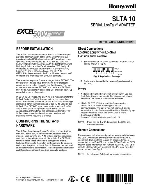
<strong>SLTA</strong>-<strong>10</strong> SERIAL LonTalk® ADAPTEREstablishing <strong>SLTA</strong>Link Manager Connection to Remote Site.1. Click <strong>SLTA</strong>Link Manager.2. From menu select Link then New.3. Enter Name and select Remote for Link type: (SeeFig. 5).4. Select Next to go to the next screen.Fig. 5. Link Description Screen.5. Enter phone number of remote site (see Fig. 6).6. Select modem from Connect Using pull down menu.Fig. 6. Dialing Address Screen.NOTE:Modems listed in Connect Using werepreviously configured by Win 95 system.7. Select Next to accept the information and continue.8. No entry is required in the Link Properties screen(see Fig. 7). Select Finish to proceed.Fig. 7. Link Properties Screen.3 95-7511—2
<strong>SLTA</strong>-<strong>10</strong> SERIAL LonTalk® ADAPTERInterfaceService Button S2Service LEDDS1EIA-232 Data PortJ5Network Connector 2 positionJ1Unregulated AC/DC powerinput 2 positionJ3Unregulated AC/DC powerinput barrel connectorJ2Power indicator LEDDS2Table 1. <strong>SLTA</strong>-<strong>10</strong> Interface.FunctionPressing this switch grounds the service request pin on the Neuron® Chip inside the<strong>SLTA</strong>-<strong>10</strong>. While this switch is pressed, the service LED should light to maximum intensity.Yellow (LED) Indicates the Service Button is being pressed. If the Service button is not beingpressed, there are three possibilities:ON: The <strong>SLTA</strong>-<strong>10</strong> firmware has detected an unrecoverable error and/or the node has noapplication. Reboot the <strong>SLTA</strong>-<strong>10</strong> from another network interface on the channel.Blinking: Node is configured.OFF: Node is configured or there is no power. Check LED.Connector for the EIA-232 serial I/O port.Standard DB9 female connection.Orange connector for attachment to a twisted pair channel. The provided mating plug isWeidmüller PN135606 (obtain locally).Black connector for the power input. The provided mating plug is Weidmüller PN125911(obtain locally).Female 2.1 mm inside diameter and 5.5 mm outside diameter power input barrel connector.Green LED indicates presence of input power of the <strong>SLTA</strong>-<strong>10</strong>.CABLING AND CONNECTIONSEIA-232 devices are configured as either Data CircuitterminatingEquipment (DCE), or as Data TerminalEquipment (DTE). The <strong>SLTA</strong>-<strong>10</strong> is a DCE device. A DCEdevice connects to a DTE device unless a null modemcable is used. Using a null modem cable, a DCE deviceconnects to another DCE device, and a DTE device canconnect to another DTE device.The standard configuration for a PC port is a DTE device.A PC usually takes the terminal role in communications.Modems should always be DCE devices. To connect an<strong>SLTA</strong>-<strong>10</strong> to a PC, connect one end of the serial cable tothe <strong>SLTA</strong>-<strong>10</strong>, and the other end of the cable to the PCserial port. Connecting an <strong>SLTA</strong>-<strong>10</strong> to a modem, requiresa special null modem cable.NOTE:A standard off-the-shelf null modem cable doesnot work with this configuration.Honeywell offers the <strong>SLTA</strong>-<strong>10</strong> Null Modem Cable (partnumber 32000<strong>10</strong>0-0<strong>10</strong>) that is a DB-9 male to DB-25 malenull modem cable.Attaching <strong>SLTA</strong>-<strong>10</strong> to a ModemIMPORTANTYou must use the specific null modem cabledescribed in Table 2, to attach the <strong>SLTA</strong>-<strong>10</strong> to amodem.Table 2. DCE Modem To <strong>SLTA</strong>-<strong>10</strong> Connection (DB-25To DB-9).ModemSignalNameCable DB-25 MaleCableDB-9Male<strong>SLTA</strong>-<strong>10</strong>(DCE) DB-9FemaleRXD—Pin 3 Pin 3 Pin 3 TXD—Pin 3TXD—Pin 2 Pin 2 Pin 2 RXD—Pin 2DCD—Pin 8 Pin 8 Pin 4 DTR—Pin 4DTR—Pin 20RTS—Pin 4Pin 20 andPin 4Pin 6 DSR—Pin 6GND—Pin 7 Pin 7 Pin 5 GND—Pin 5See Fig. 11 to attach an <strong>SLTA</strong>-<strong>10</strong> to a modem.MODEMDB25MALE<strong>SLTA</strong>-<strong>10</strong> NULLMODEM CABLEDB9MALEFig. 11. Attach <strong>SLTA</strong>-<strong>10</strong> to a modem.<strong>SLTA</strong>-<strong>10</strong>M17231ACAUTIONEquipment Damage.This product contains components that aresensitive to static electricity. Before installing orremoving the network or serial cables, touch earthground with your hand to discharge any staticelectricity that may have accumulated.5 95-7511—2
<strong>SLTA</strong>-<strong>10</strong> SERIAL LONTALK ADAPTERAttach <strong>SLTA</strong>-<strong>10</strong> to a PC with DB-9Connectors (Direct Connection).When connecting to a PC equipped with a DB-9connector, use a straight-through cable with one endterminating in a DB-9 male connector and the other endterminating in a DB-9 female connector. See Table 3.1. Plug the male end of the DB-9 connector into the<strong>SLTA</strong>-<strong>10</strong>.2. Plug the female end of the DB-9 into the serial I/Oport.Table 3. PC DB-9 To <strong>SLTA</strong>-<strong>10</strong> DB-9 Connection.SignalNamePCConnectorDB-9 MaleCableDB-9FemaleCableDB-9Male<strong>SLTA</strong>(DCE)DB-9FemaleRXD Pin 3 Pin 3 Pin 2 Pin-2TXD Pin 3 Pin 3 Pin 3 Pin 3SignalGround Pin 5 Pin 5 Pin 5 Pin 5PC (DTE)DB25FEMALEDB9MALE<strong>SLTA</strong>-<strong>10</strong>Fig. 13. DB-9 to DB-25 cable connection.Attaching the <strong>SLTA</strong>-<strong>10</strong> to a NetworkM8650CThe network connector for the <strong>SLTA</strong>-<strong>10</strong> is an orange, twoconductorblock type. Use the 2-pin conductor that comeswith the <strong>SLTA</strong>-<strong>10</strong> to connect to the twisted-pair network.See Fig. 14.1. Connect the mini-phone plug end of the 32000180-009 <strong>SLTA</strong> Connector Cable to the LONWORKS porton either a controller or a wall module.2. Connect the wire end of the to the <strong>SLTA</strong>-<strong>10</strong>.NOTEBOOK PCFig. 12 shows a DB-9 cable connecting a PC and an<strong>SLTA</strong>-<strong>10</strong>.PC (DTE)DB9FEMALEDB9MALE<strong>SLTA</strong>-<strong>10</strong>M8649CPCSERIALPORTSHIELDEDINTERFACECABLEQ7760A<strong>SLTA</strong>-<strong>10</strong>Fig. 12. DB-9 cable connection.Attach <strong>SLTA</strong>-<strong>10</strong> to a PC with DB-25Connectors (Direct Connection).Some PC serial I/O ports have a 25-pin male DB-25connector.<strong>SLTA</strong>-<strong>10</strong>CONNECTORCABLEE-BUSPORTM11943AFig. 14. Connecting the portable operator terminal tothe LONWORKS Bus.Fig. 15 shows the <strong>SLTA</strong>-<strong>10</strong> cable.When connecting to a PC equipped with a DB-25connector, use a straight-through cable with one endterminating in a DB-9 male connector and the other endterminating in a DB-25 female connector. See Table 4.1. Plug the male end of the DB-9 connector into the<strong>SLTA</strong>-<strong>10</strong>.2. Plug the female end of the DB-25 into the serial I/Oport.Table 4. PC DB-25 To <strong>SLTA</strong>-<strong>10</strong> DB-9 Connection.SignalNamePCConnectorDB-25MaleCableDB-25FemaleCableDB-9Male<strong>SLTA</strong>(DCE)DB-9FemaleRXD Pin 3 Pin 3 Pin 2 Pin-2TXD Pin 2 Pin 2 Pin 3 Pin 3SignalGround Pin 7 Pin 7 Pin 5 Pin 5Fig. 13 shows a DB-25 to DB-9 cable connecting a PC andan <strong>SLTA</strong>-<strong>10</strong>.Fig. 15. <strong>SLTA</strong>-<strong>10</strong> Connector Cable.M17225Supply power to the <strong>SLTA</strong>-<strong>10</strong> after it is connected to thedesired network. Table 5 has the specifications for powerinputs to the <strong>SLTA</strong>-<strong>10</strong>. The barrel connector input, J2, is astandard female power plug with a 2.1 mm inside diameterand a 5.5 mm outside diameter (LZR Electronics partnumber HP114A, Radio Shack catalog number 274-1569,or equivalent, obtain locally). Echelon recommends asurge protector between the AC mains and the powersupply.Power supply jack J3 provides screw terminals with aprovided Weidmüller input connector (PN 11261). Thisallows the <strong>SLTA</strong>-<strong>10</strong> to connect to a 9 to 30 Vac/Vdc powersupply.95-7511—2 6
<strong>SLTA</strong>-<strong>10</strong> SERIAL LonTalk® ADAPTERTable 5. <strong>SLTA</strong>-<strong>10</strong> Power Supply Requirements.AbsolutePower Minimum Nominal MaximumUnregulatedDC+9 Vdc +12 Vdc +30 VdcUnregulatedAC9 Vac 24 Vac 30 VacWhen power is connected, the yellow service LED flashesbriefly and the green power indicator LED turns on. Oncean <strong>SLTA</strong>-<strong>10</strong> is powered and configured, the service LEDremains off unless the service request switch is pressed.IMPORTANTDo not attempt to power an <strong>SLTA</strong>-<strong>10</strong> from JP2and JP3 simultaneously. Mechanical insertion ofa connector into JP2 disables the input to JP3(See Fig. <strong>10</strong>).ORDERING INFORMATIONAvailable Accessories:Part number 32000180-009 Portable Operations Kit(includes 9 Vdc power supply and <strong>SLTA</strong>-<strong>10</strong> connectorcable).Part number 32000180-0<strong>10</strong> Modem Installation Cable(includes special null modem cable).LONWORKS®, LonTalk®, Neuron®, LONSPEC,LONSTATION, LONSTAT are registered trademarks ofEchelon® Corporation.7 95-7511—2
Home and Building Control Home and Building Control Home and Building Control ProductsHoneywell Inc. Honeywell Limited-Honeywell Limitee Honeywell AGHoneywell Plaza 155 Gordon Baker Road Böblinger Straße 17P.O. Box 524 North York Ontario D-71<strong>10</strong>1 SchönaichMinneapolis, MN 55408-0524 M2H 3N7 Phone (49-7031) 637-01Fax (49-7031) 637-49395-7511—2 J.D. Rev. 5-99Printed in U.S.A. on recycledpaper containing at least <strong>10</strong>%post-consumer paper fibers.www.honeywell.com