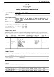
Microsoft Word - DRIMS-#4627288-v1-Pluto_LNG_ ... - Woodside
Microsoft Word - DRIMS-#4627288-v1-Pluto_LNG_ ... - Woodside
Microsoft Word - DRIMS-#4627288-v1-Pluto_LNG_ ... - Woodside

Create successful ePaper yourself
Turn your PDF publications into a flip-book with our unique Google optimized e-Paper software.
FOSTER WHEELERWORLEYPARSONSPROJECT REPORTMARINE TREATED WASTEWATERDISCHARGE MANAGEMENT PLANXA6400AH0005PAGE 3 of 70REV 2DSN 54988TABLE OF CONTENTS1. INTRODUCTION 41.1 Purpose 41.2 Approval and Distribution 41.3 Acronyms and Abbreviations 82. OVERVIEW OF WASTEWATER COLLECTION, TREATMENT ANDDISPOSAL 102.1 Re-use and Disposal Philosophy 102.2 Wastewater Collection, Treatment and Disposal Systems Design 113. MARINE TREATED WASTEWATER DISCHARGE MANAGEMENT PLAN173.1 Management Plan Objectives 173.2 Multi-User Brine Return Line Outfall Zone - Environmental Values,Environmental Quality Objectives, Levels of Ecological Protection 183.3 Discharge Regime and Flow Rate 183.4 Material Balance and Inventories from Effluent Treatment Plant 203.5 Compliance with Relevant Guidelines and Environmental Impacts 283.6 Water Quality Monitoring Programme 353.7 Implementation of the Marine Treated Wastewater Discharge ManagementPlan 374. CONTINGENCY WASTEWATER MANAGEMENT PLAN 404.1 Availability and Sparing Philosophy 404.2 Emergency Preparedness and Response 404.3 Management Options for Out of Specification Effluent 415. DOCUMENTS 425.1 References 425.2 Figures 445.3 Appendices 44Appendix A Assessment of Best Practice Technologies for Contaminant and NutrientMinimisationAppendix B Assessment of <strong>Pluto</strong> Toxicity Effluent and Fate (SKM 2008)Y:\6.0_HSE\6.1 Environment\Environmental Management Plans (EMPs)\Marine Treated Waste Water Discharge ManagementPlan\Rev 2\<strong>DRIMS</strong>-<strong>#4627288</strong>-<strong>v1</strong>-<strong>Pluto</strong>_<strong>LNG</strong>_-_Draft_Marine_Treated_Wastewater_Discharge_Management_Plan_(Rev_2)(5).doc14744-64-EN-PP-001_Rev 0
FOSTER WHEELERWORLEYPARSONSPROJECT REPORTMARINE TREATED WASTEWATERDISCHARGE MANAGEMENT PLANXA6400AH0005PAGE 4 of 70REV 2DSN 549881. INTRODUCTION1.1 PurposeThis Marine Treated Wastewater Discharge Management Plan (MTWDMP) hasbeen developed to ensure that disposal of treated wastewater from operation ofthe <strong>Pluto</strong> <strong>LNG</strong> Project (the Project) is undertaken and managed in a way thatreduces the environmental impacts to as low as reasonably practical (ALARP).The MTWDMP also incorporates the requirements of Ministerial StatementNo. 747, subsequently updated to 757. Table 1 outlines the sections within theMTWDMP where each of these requirements is addressed.1.2 Approval and DistributionThe MTWDMP will be implemented upon approval of the Western AustralianMinister for the Environment.Once approved, it will be made publicly available via <strong>Woodside</strong>’s <strong>Pluto</strong> <strong>LNG</strong>Project website:http://www.woodside.com.au/Our+Business/Projects/<strong>Pluto</strong>/Approval+Process/Environmental+Approval.htmThis MTWDMP will be reviewed prior to commencement of operations andperiodically throughout the life of the <strong>Pluto</strong> Project to ensure that anyimprovements and/or changes in wastewater management are reflected in thisPlan. Revised Plans will be provided to the DEC for approval where significantchanges in wastewater management are proposed and when the <strong>Pluto</strong> Onshore<strong>LNG</strong> Processing Plant Licence, issued under Part V of the EnvironmentalProtection Act 1986 (EP Act), is obtained (projected 2010).Y:\6.0_HSE\6.1 Environment\Environmental Management Plans (EMPs)\Marine Treated Waste Water Discharge ManagementPlan\Rev 2\<strong>DRIMS</strong>-<strong>#4627288</strong>-<strong>v1</strong>-<strong>Pluto</strong>_<strong>LNG</strong>_-_Draft_Marine_Treated_Wastewater_Discharge_Management_Plan_(Rev_2)(5).doc14744-64-EN-PP-001_Rev 0
FOSTER WHEELERWORLEYPARSONSPROJECT REPORTMARINE TREATED WASTEWATERDISCHARGE MANAGEMENT PLANXA6400AH0005PAGE 5 of 70REV 2DSN 54988Table 1: Cross Reference of the MTWDMP with Ministerial Statement No. 757 - Section 7Deepwater Marine Outfall Conditions under Ministerial Statement No. 7577-1 If a marine wastewater discharge is required by the proponent, the proponent shallconstruct the associated infrastructure so that wastewater is discharged into water of depthgreater than 30 metres outside the Dampier Archipelago, unless otherwise determined bythe CEO under Part V of the Act.7-2 Prior to construction of the wastewater treatment plant or the marine outfall, whichever isthe sooner, the proponent, in consultation with Department of Environment andConservation, shall prepare a Marine Treated Wastewater Discharge Management Plan tothe requirements of the Minister for the Environment on advice of the EnvironmentalProtection Authority.The objective of this Plan is to ensure that the discharge of treated wastewater is managedto achieve simultaneously the following Environmental Quality Objectives as described inthe document, Pilbara Coastal Water Quality Consultation Outcomes: EnvironmentalValues and Environmental Quality Objectives (Department of Environment, March 2006):• Maintenance of ecosystem integrity with spatially-assigned levels of protection;• Maintenance of aquatic life for human consumption assigned to all parts of the marineenvironment surrounding the ocean outlet;• Maintenance of primary contact recreation values assigned to all parts of the marineenvironment surrounding the ocean outlet;• Maintenance of secondary contact recreation values assigned to all parts of the marineenvironment surrounding the ocean outlet;• Maintenance of aesthetic values assigned to all parts of the marine environmentsurrounding the ocean outlet;• Maintenance of cultural and spiritual values assigned to all parts of the marineenvironment surrounding the ocean outlet; and• Maintenance of Industrial Water Supply.This Plan shall address the following:1. determination of the effect of wastewater flow rate on the number of dilutions the diffuseris predicted to achieve within the zone of initial dilution at maximum flow rate;2. setting of environmental values, environmental quality objectives and levels of ecologicalprotection to be achieved around the outfall;3. identification of a range of feasible and practical management options and theenvironmental quality indicators and associated “trigger” levels for the implementation ofremedial, management and/or preventative actions to protect the water quality and themarine environment based on the guidelines and recommended approaches inANZECC/ARMCANZ (2000);4. Whole Effluent Toxicity (WET) testing of wastewater, consistent with ANZECCrequirements, and addressing the items in schedule 5 (attached);5. redesign and incorporation of a new diffuser, including timelines, in the event that theWET testing results show that the original wastewater diffuser is not achieving sufficientdilutions to meet a high level of ecological protection at the edge of the mixing zone;6. verification of diffuser performance in terms of achieving the required number of initialdilutions under low energy/calm meteorological and sea-state conditions to achieve a highlevel of ecosystem protection (99% species protection) at the edge of the approved mixingzone;MTWDMP SectionSection 2.1(NB: WorksApproval includedin separateapplicationdocument)Section 3 andSection 4Y:\6.0_HSE\6.1 Environment\Environmental Management Plans (EMPs)\Marine Treated Waste Water Discharge ManagementPlan\Rev 2\<strong>DRIMS</strong>-<strong>#4627288</strong>-<strong>v1</strong>-<strong>Pluto</strong>_<strong>LNG</strong>_-_Draft_Marine_Treated_Wastewater_Discharge_Management_Plan_(Rev_2)(5).doc14744-64-EN-PP-001_Rev 0
FOSTER WHEELERWORLEYPARSONSPROJECT REPORTMARINE TREATED WASTEWATERDISCHARGE MANAGEMENT PLANXA6400AH0005PAGE 6 of 70REV 2DSN 54988Table 1: Cross Reference of the MTWDMP with Ministerial Statement No. 757 - Section 7Deepwater Marine Outfall Conditions under Ministerial Statement No. 7577. a monitoring program to permit determination of whether the water quality objectives arebeing met; and8. protocols and schedules for reporting performance against the Environmental QualityObjectives using the environmental quality trigger levels.7-3 The proponent shall implement the Marine Treated Wastewater Discharge ManagementPlan required by condition 7-2.7-4 The proponent shall make the Marine Treated Wastewater Discharge Management Planrequired by condition 7-2 publicly available in a manner approved by the CEO.7-5 Prior to submitting a Works Approval application for the wastewater treatment plant, theproponent shall:1. characterise in detail the physical and chemical composition and flow rates of allwastewater streams within the site and, using the toxicity of mixtures principles, predict thetheoretical toxicity of the combined wastewater after treatment;2. determine, for all contaminants and nutrients, the total annual loads of contaminants andnutrients in the wastewater discharge exiting the site; and3. determine, for normal and worst-case conditions, the concentrations of contaminantsand nutrients (for agreed averaging periods) in the wastewater discharge exiting the site.7-6 Prior to submitting a Works Approval application for the wastewater treatment plant, theproponent shall demonstrate that the wastewater discharge will meet “best practicabletechnology” and waste minimisation principles for contaminants and nutrients.7-7 Prior to submitting a Works Approval application for the wastewater treatment plant, theproponent shall design, and subsequently operate, plant and equipment on the site suchthat:1. the contaminant concentrations in the wastewater effluent from the site, just prior to entryto the wastewater discharge system, meet (in order of preference):• the ANZECC/ARMCANZ (2000) 99% species protection level; or• the ANZECC/ARMCANZ (2000) 99% species protection level at the edge of anapproved mixing zone;2. the concentrations of contaminants in the wastewater effluent which can potentially bioaccumulate/ bio-concentrate meet the ANZECC/ARMCANZ (2000) 80% speciesprotection trigger levels just prior to entry into the wastewater discharge system; and3. mass balances and inventories of toxicants can be maintained throughout the life of theplant so that their fate can be traced.7-8 Within three months following commissioning and stabilising of plant operations, theproponent shall conduct an analysis of effluent properties and contaminant concentrations,to an analytical limit of reporting agreed by the Department of Environment andConservation, demonstrating that they are substantially consistent with predictions.7-9 Prior to operation, the proponent shall develop a Contingency Wastewater ManagementPlan which considers alternate options for wastewater disposal in the event that theEnvironmental Quality Objectives are not met as determined through Whole EffluentToxicity testing, diffuser performance monitoring or environmental quality monitoring, to therequirements of the Minister for the Environment.7-10 In the event that the treatment plant malfunctions or goes off-line, the proponent shallinclude within the Contingency Wastewater Management Plan required by condition 7-9alternative options for wastewater disposal to the timing and other requirements of theMinister for the Environment.MTWDMP SectionSection 1.2 andSection 3.7Section 1.2 andSection 3.7Section 3 andAppendix B(NB: WorksApproval includedin separateapplicationdocument)Appendix ASection 3.4 and3.5(NB: WorksApproval includedin separateapplicationdocument)Section 3.6Section 4Section 4Y:\6.0_HSE\6.1 Environment\Environmental Management Plans (EMPs)\Marine Treated Waste Water Discharge ManagementPlan\Rev 2\<strong>DRIMS</strong>-<strong>#4627288</strong>-<strong>v1</strong>-<strong>Pluto</strong>_<strong>LNG</strong>_-_Draft_Marine_Treated_Wastewater_Discharge_Management_Plan_(Rev_2)(5).doc14744-64-EN-PP-001_Rev 0
FOSTER WHEELERWORLEYPARSONSPROJECT REPORTMARINE TREATED WASTEWATERDISCHARGE MANAGEMENT PLANXA6400AH0005PAGE 7 of 70REV 2DSN 54988Table 1: Cross Reference of the MTWDMP with Ministerial Statement No. 757 - Section 7Deepwater Marine Outfall Conditions under Ministerial Statement No. 7577-11 In the event that the Environmental Quality Objectives are not being met, the proponentshall implement the Contingency Wastewater Management Plan required by condition 7-9.7-12 The proponent shall review and revise the Contingency Wastewater Management Planrequired by condition 7-9, as and when directed by the CEO.7-13 The proponent shall make any revisions of the Contingency Wastewater ManagementPlan, as required by condition 7-12, publicly available in a manner approved by the CEO.MTWDMP SectionSection 4Section 4Section 4Y:\6.0_HSE\6.1 Environment\Environmental Management Plans (EMPs)\Marine Treated Waste Water Discharge ManagementPlan\Rev 2\<strong>DRIMS</strong>-<strong>#4627288</strong>-<strong>v1</strong>-<strong>Pluto</strong>_<strong>LNG</strong>_-_Draft_Marine_Treated_Wastewater_Discharge_Management_Plan_(Rev_2)(5).doc14744-64-EN-PP-001_Rev 0
FOSTER WHEELERWORLEYPARSONSPROJECT REPORTMARINE TREATED WASTEWATERDISCHARGE MANAGEMENT PLANXA6400AH0005PAGE 8 of 70REV 2DSN 549881.3 Acronyms and AbbreviationsALARPaMDEAANZECCAOCARMCANZBATBOD 5 / BODBPMBTEXCDCDFCFUCOCCODCO 2CPIDCSDECDOEOFEPAAs Low As Reasonably Practicalactivated Methyl Di-Ethanol AmineAustralian and New Zealand Environment and Conservation CouncilAccidentally Oil Contaminated (drainage system)Agriculture and Resource Management Council of Australia and New ZealandBest Available TechnologyBiochemical Oxygen Demand (5 day)Best Practicable MeasuresBenzene, Toluene, Ethyl Benzene, XyleneClosed Drainage (system)Controlled Discharge FacilityColony-Forming UnitsContinuously Oil Contaminated (drainage system)Chemical Oxygen DemandCarbon DioxideCorrugated Plate interceptorDistributed Control SystemDepartment of Environment and ConservationDissolved OxygenEntirely Oil-Free (drainage system)Environmental Protection AuthorityEP Act Environmental Protection Act 1986EQCEQGEQMFEQOETPEVFWWHATLATLEP<strong>LNG</strong>MBRMCCMEGEnvironmental Quality CriteriaEnvironmental Quality GuidelineEnvironmental Quality Management FrameworkEnvironmental Quality ObjectiveEffluent Treatment PlantEnvironmental ValueFoster Wheeler WorleyParsonsHighest Astronomical TideLowest Astronomical TideLevel of Ecological ProtectionLiquefied Natural GasMembrane BioReactorMotor Control CentreMono Ethylene GlycolY:\6.0_HSE\6.1 Environment\Environmental Management Plans (EMPs)\Marine Treated Waste Water Discharge ManagementPlan\Rev 2\<strong>DRIMS</strong>-<strong>#4627288</strong>-<strong>v1</strong>-<strong>Pluto</strong>_<strong>LNG</strong>_-_Draft_Marine_Treated_Wastewater_Discharge_Management_Plan_(Rev_2)(5).doc14744-64-EN-PP-001_Rev 0
FOSTER WHEELERWORLEYPARSONSPROJECT REPORTMARINE TREATED WASTEWATERDISCHARGE MANAGEMENT PLANXA6400AH0005PAGE 9 of 70REV 2DSN 54988MLMPNMPPEMUBRLMTWDMPPACPEPSUPWRASRORWPSTPTDSTOCTIDSTSSUVMega litreMost-Probable-NumberMacro Porous Polymer ExtractionMulti User Brine Return Line (part of Water Corporation’s infrastructure for BurrupPeninsula Desalinated Water and Seawater Supplies Project).Marine Treated Wastewater Discharge Management PlanPowdered Activated CarbonPopulation EquivalentPractical Salinity UnitProduced WaterReturn Activated SludgeReverse OsmosisRecovered Water PlantSewage Treatment PlantTotal Dissolved SaltsTotal Organic CarbonTotal Inorganic Dissolved SaltsTotal Suspended SolidsUltra violetµL Micro litresWAWBPLWETWWWWTPWestern Australia<strong>Woodside</strong> Burrup Pty LtdWhole Effluent ToxicityWaste WaterWastewater Treatment PlantY:\6.0_HSE\6.1 Environment\Environmental Management Plans (EMPs)\Marine Treated Waste Water Discharge ManagementPlan\Rev 2\<strong>DRIMS</strong>-<strong>#4627288</strong>-<strong>v1</strong>-<strong>Pluto</strong>_<strong>LNG</strong>_-_Draft_Marine_Treated_Wastewater_Discharge_Management_Plan_(Rev_2)(5).doc14744-64-EN-PP-001_Rev 0
FOSTER WHEELERWORLEYPARSONSPROJECT REPORTMARINE TREATED WASTEWATERDISCHARGE MANAGEMENT PLANXA6400AH0005PAGE 10 of 70REV 2DSN 549882. OVERVIEW OF WASTEWATER COLLECTION, TREATMENT ANDDISPOSAL2.1 Re-use and Disposal PhilosophyThroughout the <strong>Pluto</strong> Project environmental assessment process, both State andCommonwealth regulators advised that wastewater discharges to Mermaid Soundshould be avoided and all options for reuse to be exhausted before a discharge iscontemplated (refer to Environmental Protection Authority (EPA) Bulletin 1259).As a consequence, various water recovery studies and re-use options have beenassessed by <strong>Woodside</strong> (FWW 2006, FWW 2008). The most significant outcomeof these investigations included the revision of the reference case for wastewatertreatment to provide for extensive treatment of all wastewater streams to meetplant service water specifications. This enables extensive reuse of treatedwastewater within the <strong>Pluto</strong> <strong>LNG</strong> plant resulting in substantially reduced surplusvolume requiring disposal.However, water balance studies indicate that treated effluent will at times be inexcess of on-site service water demand. Furthermore, no re-use application hasbeen identified for the concentrate stream from the <strong>Pluto</strong> demineralised (Demin)water plant. Thus “zero discharge” is impractical without considering otherdisposal options.Initial discussions between <strong>Woodside</strong> and third parties on the potential market for<strong>Pluto</strong>'s excess treated reuse water were positive. However, any agreement with athird party to accept <strong>Pluto</strong>'s treated water requires a reliable/predictable supply. Inthe short to medium term the <strong>Pluto</strong> facilities will utilise all of the normal producedvolume of reuse water. Volumes in excess of the <strong>Pluto</strong> site requirements will onlybe available on an infrequent and unplanned basis, primarily associated with stormevents. Therefore, given the uncertainty associated with volumes that could bemade available for third party reuse, discussions with third parties have beensuspended. However, as the <strong>Pluto</strong> wellfield ages, produced water quantities areexpected to increase and will eventually result in reuse water quantities thatconsistently exceed <strong>Pluto</strong> site service water requirements. At that stage,<strong>Woodside</strong> commit to re-commence discussions with interested parties.Thus, the option to discharge to the ocean needs to be retained to provide adisposal route for demineralised water plant concentrate and infrequent volumes ofexcess treated effluent. Options for ocean discharge considered (<strong>Woodside</strong> 2008)included:1. Discharge into water of depth greater than 30 m outside the DampierArchipelago (refer to Ministerial Condition 7-1),2. Discharge via a purpose built diffuser located at the end of the <strong>Pluto</strong> exportjetty, andY:\6.0_HSE\6.1 Environment\Environmental Management Plans (EMPs)\Marine Treated Waste Water Discharge ManagementPlan\Rev 2\<strong>DRIMS</strong>-<strong>#4627288</strong>-<strong>v1</strong>-<strong>Pluto</strong>_<strong>LNG</strong>_-_Draft_Marine_Treated_Wastewater_Discharge_Management_Plan_(Rev_2)(5).doc14744-64-EN-PP-001_Rev 0
FOSTER WHEELERWORLEYPARSONSPROJECT REPORTMARINE TREATED WASTEWATERDISCHARGE MANAGEMENT PLANXA6400AH0005PAGE 11 of 70REV 2DSN 549883. Discharge into Water Corporation’s existing multi-user brine return line(MUBRL) with outfall located in King Bay.Option ‘2’ was included as the base case in the PER; however, in line withregulatory and stakeholder preference (refer to EPA Bulletin 1259), option ‘3’ wasalso taken forward for detailed consideration. In summary, discharge to WaterCorporation’s existing MUBRL has now been adopted as the preferred approachbased on environmental grounds given:• the outfall and mixing zone has environmental approval (refer to MinisterialStatement 594);• ANZECC (2000) guidelines are met at the point of discharge into the MUBRLfor most contaminants, and at the edge of the approved mixing zone for allcontaminants;• the option utilises an existing outfall and support infrastructure; and• the outfall has sufficient line capacity to receive surplus treated effluent fromthe <strong>Pluto</strong> Project.Option ‘1’ would involve construction of a pipeline on the seabed, approximately25 to 35 km long. This option has been eliminated from further assessment due topotential seabed and coral impacts associated with pipeline construction, capitalexpenditure (estimated to be in excess of $50 million) and the operational costsassociated with pumping and maintenance. In addition, the ETP has beendesigned to maximise reuse of wastewater, as plant service water, hence, it isconsidered unwarranted to require <strong>Woodside</strong> to construct a 25 – 35 km pipeline todischarge surplus or non-routine discharges of wastewater treated to meet a highspecification.2.2 Wastewater Collection, Treatment and Disposal Systems DesignProvided in Sections 2.2.1 to 2.2.7 is a brief summary of the systems selected forthe collection, treatment, re-use and disposal of wastewater streams for the <strong>Pluto</strong>Project.A wastewater process flow diagram is provided in Figure 1. Further detail relatingto the design and selection of best practice technologies is contained withinAppendix A.Y:\6.0_HSE\6.1 Environment\Environmental Management Plans (EMPs)\Marine Treated Waste Water Discharge ManagementPlan\Rev 2\<strong>DRIMS</strong>-<strong>#4627288</strong>-<strong>v1</strong>-<strong>Pluto</strong>_<strong>LNG</strong>_-_Draft_Marine_Treated_Wastewater_Discharge_Management_Plan_(Rev_2)(5).doc14744-64-EN-PP-001_Rev 0
FOSTER WHEELERWORLEYPARSONSPROJECT REPORTMARINE TREATED WASTEWATERDISCHARGE MANAGEMENT PLANXA6400AH0005PAGE 12 of 70REV 2DSN 54988Figure 1 – <strong>Pluto</strong> Effluent Treatment and Reuse Process SchematicY:\6.0_HSE\6.1 Environment\Environmental Management Plans (EMPs)\Marine Treated Waste Water Discharge ManagementPlan\Rev 2\<strong>DRIMS</strong>-<strong>#4627288</strong>-<strong>v1</strong>-<strong>Pluto</strong>_<strong>LNG</strong>_-_Draft_Marine_Treated_Wastewater_Discharge_Management_Plan_(Rev_2)(5).doc14744-64-EN-PP-001_Rev 0
FOSTER WHEELERWORLEYPARSONSPROJECT REPORTMARINE TREATED WASTEWATERDISCHARGE MANAGEMENT PLANXA6400AH0005PAGE 13 of 70REV 2DSN 549882.2.1 Effluent Streams, Collection and Drainage SystemsDrainage systems shall be provided to ensure the segregation and direction toappropriate treatment and/or disposal facilities of effluent from the process, utilitiesand contaminated surface water streams, as well as domestic effluent from the<strong>LNG</strong> Plant site. These effluent streams and collection systems are described inthe following paragraphs below.Entirely Oil-Free (EOF) - open surface water drainage system designed to collectand direct clean water from outside of kerbed areas around process facilities (SiteB) and bunded areas around the storage tanks (Site A and B). There is no risk ofcontamination of EOF water from the <strong>Pluto</strong> <strong>LNG</strong> facilities. The EOF drainagesystem shall direct EOF water via a network of open channels, ditches, sumps andpipes where it can be disposed of to natural drainage lines around the site, withouttreatment. In the event of a spill within EOF areas, implementation of spillresponse procedures will ensure immediate cleanup of spills from EOF surfacesand maintain clean EOF areas.Accidentally Oil-Contaminated (AOC) - collection of surface water run-off bymeans of a network of surface drain channels and liquid filled underground pipeheaders, which discharge effluent under gravity to the Controlled DischargeFacility (CDF). AOC drainage areas are considered to be areas in which an oilyemission is not expected to occur during normal operation, but which is at risk ofaccidental contamination with oil or other contaminants, i.e. accidental spills.Accidental spillages shall be contained by kerbs or floor slopes in the processareas and bunds for storage tank areas. AOC areas are designed to limit ingressof rain and prevent overflow to the surrounding paved areas. Implementing spillresponse procedures will also ensure immediate clean-up of spillages from AOCsurfaces and maintain clean kerbed and bunded areas. Once collected in theCDF, AOC water will be tested and either forwarded for treatment if contaminatedor released to the environment if not contaminated.Continuously Oil-Contaminated (COC) - drainage system collects any oilyleakages from equipment by localised kerbs, drip trays, drain trays, funnels, etc.Collected COC effluent shall be directed (via vacuum tanker or direct pumping) tothe oily water equalisation tanks within the effluent treatment plant (ETP) for furtherprocessing. COC sources include equipment or packages with a high potential forlubrication oil leakage (e.g. pumps, gearbox, compressor skids and hydraulicpackages) and the jetty head (condensate loading arm).Process Closed Drainage systems (CD) – includes closed process drainagesystems within the acid gas removal area containing amine compounds (aMDEA),and within the mono ethylene glycol (MEG) regeneration area containing MEG.CD systems are considered part of the unit, whereby drainage is recovered intothe process, and fluids are not discharged to the oily water drainage systems orETP.Y:\6.0_HSE\6.1 Environment\Environmental Management Plans (EMPs)\Marine Treated Waste Water Discharge ManagementPlan\Rev 2\<strong>DRIMS</strong>-<strong>#4627288</strong>-<strong>v1</strong>-<strong>Pluto</strong>_<strong>LNG</strong>_-_Draft_Marine_Treated_Wastewater_Discharge_Management_Plan_(Rev_2)(5).doc14744-64-EN-PP-001_Rev 0
FOSTER WHEELERWORLEYPARSONSPROJECT REPORTMARINE TREATED WASTEWATERDISCHARGE MANAGEMENT PLANXA6400AH0005PAGE 14 of 70REV 2DSN 54988Produced Water (PW) – is primarily condensed water with a small amount offormation water. The condensed water flow is expected to be relatively consistent;however, formation water is expected to increase in volume with time as thewellfield ages. PW will be dissolved into the MEG phase in the offshore trunk lineand will be carried onshore as a multiphase mixture of gas, condensate andMEG/water. Onshore, the MEG/water phase shall be separated from thehydrocarbon gas and condensate in the slug catcher and the MEG/water phasesent to the MEG regeneration system.The aqueous vapour phase overhead from the MEG distillation process shall becondensed to produce, effectively, distilled water with some MEG and benzene,toluene, ethyl benzene and xylene (BTEX), which is pumped directly to the ETP fortreatment.2.2.2 Process Effluent Management and Treatment SystemsThe process effluent management and treatment systems include:• Effluent segregation and drainage collection (as described above).• Controlled Discharge Facility (CDF) - all AOC effluents from the plant areasshall be discharged through an under ground header and/or open channels tothe central CDF inlet channel. The function of the CDF is to segregate AOCdrainage and direct it to the ETP; this system also caters for rain water runoffand allows for segregation, inspection and testing of water quality before adecision is taken to discharge to the EOF surface water system if notcontaminated, or to the ETP for further treatment if contaminated. The basinswill be constructed from reinforced concrete and incorporate a first flushcompartment and a peak overflow compartment.• Effluent Treatment Plant (ETP) - for treatment of COC, contaminated AOC andproduced water. The <strong>Pluto</strong> ETP provides primary, secondary and tertiarytreatment of contaminated water prior to reuse or marine discharge via theMUBRL. These treatment systems are detailed further in the sections below.2.2.3 Primary Waste Water Treatment• Oily Water Equalisation - equalisation of the COC effluents, MEG Overheads(PW) and contaminated AOC effluent shall be provided within the oily waterequalisation tanks, which ensures homogeneity of influent flow and reducescontaminant load variations to provide a relatively consistent feed stream todownstream processes.• Oil Slops Tanks - collect free hydrocarbons separated from within the ETP.Free hydrocarbons shall arise from the CDF (from floating oil skimmers), oilywater equalisation (from in-tank oil skimmers), oily floats from the corrugatedplate interceptor (CPI) and recovered hydrocarbons from the macro porouspolymer extraction (MPPE) unit. Aqueous supernatant from the oil slops tanksshall be decanted into the effluent treatment plant COC drainage system. Oilslops shall be pumped to the condensate storage tanks.Y:\6.0_HSE\6.1 Environment\Environmental Management Plans (EMPs)\Marine Treated Waste Water Discharge ManagementPlan\Rev 2\<strong>DRIMS</strong>-<strong>#4627288</strong>-<strong>v1</strong>-<strong>Pluto</strong>_<strong>LNG</strong>_-_Draft_Marine_Treated_Wastewater_Discharge_Management_Plan_(Rev_2)(5).doc14744-64-EN-PP-001_Rev 0
FOSTER WHEELERWORLEYPARSONSPROJECT REPORTMARINE TREATED WASTEWATERDISCHARGE MANAGEMENT PLANXA6400AH0005PAGE 15 of 70REV 2DSN 54988• Corrugated Plate Interceptor (CPI) - provides removal of free hydrocarbonsand settleable sludges. Free hydrocarbons (oily floats) will drain to the oilslops tanks. Silty sludges shall be either transferred by vacuum tanker to thesludge digester tanks or tankered offsite for disposal at an approved facility.• Effluent Neutralisation - pH correction is provided for upstream of MPPE,with further pH correction prior to secondary treatment.• Effluent Cooling - to achieve stable operation and optimise biologicaltreatment, the effluent temperature shall be cooled by two-stage cooling usingevaporative cooling water and chilled water cooling.• Macro Porous Polymer Extraction (MPPE) - the BTEX compounds presentin the condensed overhead phase from the MEG regeneration process arepotentially inhibitory to bacterial growth. The MPPE unit shall reduce theBTEX contaminant levels prior to subsequent biotreatment.2.2.4 Secondary (Biological) Waste Water TreatmentBiological treatment to degrade soluble hydrocarbons and MEG shall be providedby the use of membrane bioreactors (MBR). The MBR package is an activatedsludge process which uses a semi-permeable membrane barrier system toseparate the treated effluent from the organics degrading micro-organisms. Theactivated sludge micro-organisms degrade the soluble organics to generate CO 2and excess biomass cells.Given there are no significant nutrient sources for the biomass identified in thefeed effluent stream to the ETP, the effluent will normally be dosed with nutrientsto sustain the biological treatment process, which is required to degrade solublehydrocarbons and MEG. Optimal dosing will ensure that a minimum nutrient levelis maintained to sustain biological growth within the MBR, whilst also minimisingexcess nutrient discharge via the MUBRL (Multi User Brine Line). Furtherdiscussions relating to nutrients are included in Section 3.51.2.2.5 Sludge Treatment and Disposal• Sludge Digestion - excess biosludge from the industrial biological treatmentMBR shall be pumped direct to the aerobic biosludge digester. Oily watersludges shall be transferred by vacuum tanker from the CPI sludge or offsitefor disposal by an approved contractor. The aerobic biosludge digester hastwo functions; it reduces sludge mass by aerobic endogenous degradationand provides biosludge holding capacity.Sludge Handling - the stabilised sludge shall be tankered offsite fordisposal by and approved contractor.Y:\6.0_HSE\6.1 Environment\Environmental Management Plans (EMPs)\Marine Treated Waste Water Discharge ManagementPlan\Rev 2\<strong>DRIMS</strong>-<strong>#4627288</strong>-<strong>v1</strong>-<strong>Pluto</strong>_<strong>LNG</strong>_-_Draft_Marine_Treated_Wastewater_Discharge_Management_Plan_(Rev_2)(5).doc14744-64-EN-PP-001_Rev 0
FOSTER WHEELERWORLEYPARSONSPROJECT REPORTMARINE TREATED WASTEWATERDISCHARGE MANAGEMENT PLANXA6400AH0005PAGE 16 of 70REV 2DSN 549882.2.6 Tertiary Waste Water TreatmentThe membranes contained in the MBR are ultrafiltration membranes capable ofremoving suspended solids and bacteria solids down to virus size (
FOSTER WHEELERWORLEYPARSONSPROJECT REPORTMARINE TREATED WASTEWATERDISCHARGE MANAGEMENT PLANXA6400AH0005PAGE 17 of 70REV 2DSN 549883. MARINE TREATED WASTEWATER DISCHARGE MANAGEMENT PLAN3.1 Management Plan ObjectivesIn accordance with Ministerial Condition 7-2, the objective of this Plan is to ensurethat the discharge of treated wastewater is managed to achieve the followingEnvironmental Quality Objectives, as described in the document Pilbara CoastalWater Quality Outcomes: Environmental Values and Environmental QualityObjectives (DoE 2006):• Maintenance of ecosystem integrity with spatially-assigned levels ofprotection;• Maintenance of aquatic life for human consumption assigned to all parts of themarine environment surrounding the ocean outlet;• Maintenance of primary contact recreation values assigned to all parts of themarine environment surrounding the ocean outlet;• Maintenance of secondary contact recreation values assigned to all parts ofthe marine environment surrounding the ocean outlet;• Maintenance of aesthetic values assigned to all parts of the marineenvironment surrounding the ocean outlet;• Maintenance of cultural and spiritual values assigned to all parts of the marineenvironment surrounding the ocean outlet; and• Maintenance of Industrial Water Supply.To achieve the above objectives, the proposed wastewater treatment and disposaloperations will be managed to reduce the risk of environmental impacts to ALARP.This will be achieved through implementation of “best practicable technology” inwastewater treatment, whole effluent toxicity (WET) testing to determine thetoxicity of the wastewater, day to day operational environmental management, acomprehensive monitoring programme and contingency measures.An assessment of worldwide best practicable technology for wastewater treatmentand the application of best practicable technology for <strong>Pluto</strong> wastewatermanagement is included in Appendix A.Y:\6.0_HSE\6.1 Environment\Environmental Management Plans (EMPs)\Marine Treated Waste Water Discharge ManagementPlan\Rev 2\<strong>DRIMS</strong>-<strong>#4627288</strong>-<strong>v1</strong>-<strong>Pluto</strong>_<strong>LNG</strong>_-_Draft_Marine_Treated_Wastewater_Discharge_Management_Plan_(Rev_2)(5).doc14744-64-EN-PP-001_Rev 0
FOSTER WHEELERWORLEYPARSONSPROJECT REPORTMARINE TREATED WASTEWATERDISCHARGE MANAGEMENT PLANXA6400AH0005PAGE 18 of 70REV 2DSN 549883.2 Multi-User Brine Return Line Outfall Zone - Environmental Values,Environmental Quality Objectives, Levels of Ecological ProtectionThe Pilbara Coastal Water Quality Consultation Outcomes: Environmental Valuesand Environmental Quality Objectives was released in March 2006 (DoE 2006).This document establishes an Environmental Quality Management Framework(EQMF) and presents interim environmental goals (Environmental Values, EVs,and Environmental Quality Objectives, EQOs) and spatially allocates these goals(Levels of Ecological Protection, LEPs) for state waters of the Pilbara coast.While there are no specific levels set for water quality parameters, the aim of theratings of high, moderate and low LEPs are considered to be equivalent to theANZECC (2000) guidelines for species protection, such that the high LEP isequivalent to the 99% Species Level of Protection and the moderate LEP isequivalent to the 90% Species Level of Protection, and the low LEP is equivalentto the 80% Species Level of Protection from ANZECC (2000).The 0.01 km 2 mixing zone around the MUBRL outfall has been afforded a low LEPand, at the edge of the mixing zone, a high LEP has been assigned (refer to DoE2006, Map 9, note 4). <strong>Woodside</strong> intend to use a moderate LEP (90% SpeciesLevel of Protection) in the mixing zone as a trigger level for further investigation.<strong>Woodside</strong> intends to implement the following trigger levels:- meeting ANZECC 90% species protection at end of pipe (contaminants)- meeting ANZECC 80% species protection at end of pipe (bioaccumulants/bioconcentratation)- meeting ANZECC 99% species protection at end of mixing zone.The discharge of wastewater through the MUBRL into King Bay is regulatedthrough Ministerial Statement 594 as part of Water Corporation’s DesalinatedWater and Seawater Supplies Project. As a result, <strong>Woodside</strong> has a contractualrequirement with the Water Corporation to achieve specified criteria fortemperature, concentration of biocide and antiscalent at the point of discharge intothe MUBRL.3.3 Discharge Regime and Flow Rate3.3.1 Discharge from <strong>Pluto</strong> ETP to the MUBRLThe current design assumes batch discharge to the MUBRL from the finalinspection tanks. The discharge will be intermittent and each batch will be testedor characterised prior to release. Any batch of effluent that does not meetdischarge criteria will not be discharged to the brine line. Given that discharge willbe batch discharge, instead of continuous discharge, averaging periods are notconsidered to be applicable.Y:\6.0_HSE\6.1 Environment\Environmental Management Plans (EMPs)\Marine Treated Waste Water Discharge ManagementPlan\Rev 2\<strong>DRIMS</strong>-<strong>#4627288</strong>-<strong>v1</strong>-<strong>Pluto</strong>_<strong>LNG</strong>_-_Draft_Marine_Treated_Wastewater_Discharge_Management_Plan_(Rev_2)(5).doc14744-64-EN-PP-001_Rev 0
FOSTER WHEELERWORLEYPARSONSPROJECT REPORTMARINE TREATED WASTEWATERDISCHARGE MANAGEMENT PLANXA6400AH0005PAGE 19 of 70REV 2DSN 54988When discharging, the discharge flow will be 104 m 3 /hr and will vary in frequencydepending on a number of operational parameters including:• <strong>Pluto</strong> well-field water production (i.e. during early years of operation wellfieldproduced water volume is low, and as the wellfield ages produced watervolume increases);• Status of MEG recovery operations;• Significant rainfall in past 3 days; and• Service water and demineralised water demand.Note that the following assumptions have been made:• Flow into final inspection tanks is of constant composition, and• “Shut-down” events are not regular or prolonged enough to significantly raisecontaminant concentrations or volumes to the MUBRL and subsequentlybreach guidelines.Summarised below in Table 2 are operating scenarios that typify the minimum,maximum and average discharge scenarios over the life of the <strong>Pluto</strong> Project.Table 2 – Operating Discharge ScenariosScenario1 - Min PW flow anddry weather2 - Min PW flowand wet weather3 - High PW flowand dry weather4 - High PW flowand wet weatherScenarioDescriptionAll treated effluentrecovered & reusedas service water anddemin feed.Only a portion oftreated effluentreused as servicewater, i.e. excessto requirements.Slight excess oftreated effluentproduced beyondservice waterrequirements.Only a portion oftreated effluentreused as servicewater, i.e. excessto requirements.EffluentStream(s)dischargedto MUBRLRO concentrate andbrine wastes fromdemin plant.Excess treatedeffluent, ROconcentrate andbrine wastes fromdemin plant.Excess treatedeffluent, ROconcentrate andbrine wastes fromdemin plant.Excess treatedeffluent, ROconcentrate andbrine wastes fromdemin plant.DischargeVolumeAverage 40 m 3 perday (intermittentdischarge).Average 600 m 3per day(intermittentdischarge).Average 170 m 3per day(intermittentdischarge).Average 600 m 3per day(intermittentdischarge).TDS ofdischargedeffluent2,000 - 10,000 mg/L < 1,000 mg/L < 2,000 mg/L < 1,000 mg/LY:\6.0_HSE\6.1 Environment\Environmental Management Plans (EMPs)\Marine Treated Waste Water Discharge ManagementPlan\Rev 2\<strong>DRIMS</strong>-<strong>#4627288</strong>-<strong>v1</strong>-<strong>Pluto</strong>_<strong>LNG</strong>_-_Draft_Marine_Treated_Wastewater_Discharge_Management_Plan_(Rev_2)(5).doc14744-64-EN-PP-001_Rev 0
FOSTER WHEELERWORLEYPARSONSPROJECT REPORTMARINE TREATED WASTEWATERDISCHARGE MANAGEMENT PLANXA6400AH0005PAGE 20 of 70REV 2DSN 54988It is estimated that approximately 30,000 kL of treated effluent will be discharged tothe MUBRL annually. This equates to approximately 0.04% of the total capacitydischarge rate from the MUBRL (based on approved maximum discharge of208,000 kL per day).3.3.2 Discharge from MUBRL into King BayThe Water Corporation has provided the following information with regard to itsMUBRL and ocean outfall infrastructure (pers comm. S. Wilke, CEE 2003):1. Outfall infrastructure consists of one brine break tank (2 ML capacity) locatedadjacent to Mermaid Marine, with valve opening for batch discharge once thetank is full.2. Infrastructure discharge design capacity is 208 ML/day and is estimated to becurrently operating at one third capacity with Burrup Ammonia Plant being theonly other current user of the infrastructure.3. Hydrodynamic and dispersion modelling has been undertaken to evaluate thediffuser design, effects of flow rate, and also assess impacts of tidal and windconditions on effluent dispersion.4. The MUBRL outfall and diffuser extends approximately 800 m from the end ofthe Mermaid Marine groyne. The diffuser consists of 28 nozzles at 10 mspacing (total length 280 m), with a discharge angle of 30° above horizontal.To maximise mixing of the discharge with ambient seawater, the diffuser portsare directed alternately into and away from the dominant current, anddischarge occurs at a fixed exit velocity of 4.5 m/s.5. The approved mixing zone area is 0.01 km 2 and dispersion modelling indicatesthat the diffuser arrangement achieves a 19:1 dilution at the edge of this mixingzone. This dilution rate has been verified by Water Corporation.3.4 Material Balance and Inventories from Effluent Treatment PlantFigure 2 below shows all inputs, outputs and toxicants from the proposed <strong>Pluto</strong>effluent treatment facilities.Y:\6.0_HSE\6.1 Environment\Environmental Management Plans (EMPs)\Marine Treated Waste Water Discharge ManagementPlan\Rev 2\<strong>DRIMS</strong>-<strong>#4627288</strong>-<strong>v1</strong>-<strong>Pluto</strong>_<strong>LNG</strong>_-_Draft_Marine_Treated_Wastewater_Discharge_Management_Plan_(Rev_2)(5).doc14744-64-EN-PP-001_Rev 0
FOSTER WHEELERWORLEYPARSONSPROJECT REPORTMARINE TREATED WASTEWATERDISCHARGE MANAGEMENT PLANXA6400AH0005PAGE 21 of 70REV 2DSN 54988Figure 2 – <strong>Pluto</strong> Effluent Treatment facilities inputs and outputsThe inputs and outputs shown in Figure 2 have been assessed to determine:• the type and concentration of contaminants present;• the required treatment technology for removal (refer to Appendix A foradditional information); and• the resulting contaminant levels in the various ETP output streams.Table 3 shows the outcome of this assessment for each of the main classes ofcontaminants. This assessment assists in determination of fate for allcontaminants.Inputs to the ETP are high in hydrocarbons (free and dissolved), primarily from theMEG Overhead and the COC. However, following treatment, all toxicants indischarge streams are reduced to trace concentrations.Y:\6.0_HSE\6.1 Environment\Environmental Management Plans (EMPs)\Marine Treated Waste Water Discharge ManagementPlan\Rev 2\<strong>DRIMS</strong>-<strong>#4627288</strong>-<strong>v1</strong>-<strong>Pluto</strong>_<strong>LNG</strong>_-_Draft_Marine_Treated_Wastewater_Discharge_Management_Plan_(Rev_2)(5).doc14744-64-EN-PP-001_Rev 0
FOSTER WHEELERWORLEYPARSONSPROJECT REPORTMARINE TREATED WASTEWATERDISCHARGE MANAGEMENT PLANXA6400AH0005PAGE 22 of 70REV 2DSN 54988Table 3 – Contaminants entering <strong>Pluto</strong> Effluent Treatment Plant – Sources,Treatment & OutputsETP Input ToxicantsTH*1AOCCOCCondensedMEGOverheadETP Inputs Treatment ETP OutputsDeminWater PlantWastesETP ProcessChemicalsDomesticSewageOilSkimmingCPIVentFiltersMPPE MBREmergencyAdsorptionBTEX T T H Nil Nil Nil T T T H H Nil T* Nil NilMEG T Nil T T Nil Nil T T T T Nil Nil Nil Nil NilLube Oils T T Nil Nil Nil Nil N N T H Nil Nil Nil Nil NilOther Free Hydrocarbons T H Nil Nil Nil T T T T H T Nil Nil Nil NilOther Dissolved Hydrocarbons T H T T Nil T T T T H H Nil T* T TMetals T T T T T T T T T T T T1 Nil T TAntiscalants T Nil T T T Nil T T T T Nil Nil Nil Nil NilCorrosion Inhibitors T Nil T Nil T Nil T T T T Nil Nil Nil Nil NilOther Production Chemicals T Nil Nil Nil Nil Nil T T T T Nil Nil Nil Nil NilNutrients T T Nil T H H T T T T Nil T1 Nil T TTrace levels of Toxicant may or will be present in the corresponding ETP output. For streams discharge to the environment, dischargeconcentration will be below Ministerial requirements.High Concentration of Toxicant will be present in the corresponding ETP outputAtmospheric emissions of hydrocarbons are practically minimised by use of activated carbon vent filters.Treatment process is effective for removal / reduction of this contaminant.Naturally occuring background concentrations of this contaminant are unnaffected by <strong>Pluto</strong> facility.ReuseWaterEffluentto MUBRLETPSludges /CakeOilySlopsSpentActivatedCarbonCleanSurfaceWaterDischargeAtmosphericEmissionsTreatedDomesticWastewaterSewageSludgeFlows and contaminant concentrations for all the above streams shall bemonitored and recorded for the life of the facility enabling the mass balance andfate of all contaminants to be determined.The other streams directed to the MUBRL are the combined RO concentrate andion exchange waste stream. The RO concentrate contains concentrated salts fromservice water, antiscalent and possibly biocide residues.The predicted average effluent concentrations and annual loading of the chemicalconstituents are listed in Table 4 (Table 1 in Appendix B). This data is based oncurrently available information from vendors and the Water Corporation. The datarepresent a conservative approach, by using a set of assumptions, in estimatingthe effluent inputs and quality.The following assumptions have been made in predicting contaminantconcentrations at the edge of the approved mixing zone:1. All constituent concentrations refer to the <strong>Pluto</strong> ETP wastewater streamconcentrations prior to entry to the MUBRL and at end of pipe as being thesame value: that is, no cross-subsidy, interaction or dilution effects from non-<strong>Pluto</strong> discharges (within the MUBRL) are considered.2. Assessment is based on <strong>Pluto</strong> discharge as a stand alone discharge to theMUBRL; hence, dilution with other effluents in the MUBRL has not been takeninto account.3. The effects of weathering processes and biodegradation in the mixing zone arenot accounted for.Y:\6.0_HSE\6.1 Environment\Environmental Management Plans (EMPs)\Marine Treated Waste Water Discharge ManagementPlan\Rev 2\<strong>DRIMS</strong>-<strong>#4627288</strong>-<strong>v1</strong>-<strong>Pluto</strong>_<strong>LNG</strong>_-_Draft_Marine_Treated_Wastewater_Discharge_Management_Plan_(Rev_2)(5).doc14744-64-EN-PP-001_Rev 0
FOSTER WHEELERWORLEYPARSONSPROJECT REPORTMARINE TREATED WASTEWATERDISCHARGE MANAGEMENT PLANXA6400AH0005PAGE 23 of 70REV 2DSN 549884. Hydrodynamic and dispersion modelling undertaken by the Water Corporationindicates that the diffuser arrangement achieves at least a 19:1 dilution at theedge of the 0.01km 2 mixing zone. This dilution rate has been verified in thefield by the Water Corporation. Given the relatively small effluent volumecontribution from <strong>Pluto</strong>, the resulting change in MUBRL effluent density, andthus buoyancy, is insignificant. As such, the dispersion modelling undertakenby Water Corporation remains valid and a 19:1 dilution is applied to <strong>Pluto</strong>treated effluent concentrations.5. Constituent concentrations have also been predicted at the edge of the mixingzone following dilution with seawater, and taking into account respectivebackground seawater concentrations.Assumptions 1 and 2, in particular, show the conservatism used in estimating theeffluent outputs and quality. If these assumptions are not valid, the effluent will befurther diluted before reaching the end of pipe and being discharged; hence, theconcentration at the entry to the MUBRL is reduced further, as is the concentrationat the edge of the mixing zone. Assumption 3 is important also as, over time,weathering processes and biodegradation will reduce concentrations.Production chemicals expected in the treated wastewater are also included inTable 4 including those production chemicals that may be used in the wastewatertreatment process (for example to balance pH or enhance flocculation) but will notbe discharged. That is, they will be re-circulated and/or consumed in the treatmentprocess.Table 4 provides for all constituents comparisons against appropriate water qualityguidelines (at end of pipe and at edge of mixing zone) and/or predicted no-effectconcentrations based on ecotoxicity information.Table 4 also includes the maximum expected produced wastewater concentrationsfrom the ETP. As stated in Section 3.3.1, wastewater will not be discharged if it isabove the 90% species protection threshold specification; hence, contingencieswill be implemented (Refer to Section 4) to ensure discharge meets the requiredthreshold levels.The theoretical maximum concentrations have also been calculated at the edge ofthe mixing zone. It can be seen in Table 4 that if maximum concentrations werecontinually discharged to the marine environment, the 99% species protection atthe edge of the mixing zone would still be met for all constituents.Y:\6.0_HSE\6.1 Environment\Environmental Management Plans (EMPs)\Marine Treated Waste Water Discharge ManagementPlan\Rev 2\<strong>DRIMS</strong>-<strong>#4627288</strong>-<strong>v1</strong>-<strong>Pluto</strong>_<strong>LNG</strong>_-_Draft_Marine_Treated_Wastewater_Discharge_Management_Plan_(Rev_2)(5).doc14744-64-EN-PP-001_Rev 0
FOSTER WHEELER WORLEYPARSONSPROJECT REPORTMARINE TREATED WASTEWATER DISCHARGEMANAGEMENT PLANXA6400AH0005PAGE 24 of 70REV 2DSN 54988Table 4 – Expected Constituents, Concentrations and Loadings in <strong>Pluto</strong> Treated Wastewater Stream Assessment Against Guidelines and ToxicityCriteriaConstituentHydrocarbons (HCs)Total free HCsPrimary Source(s)HC Spills within AOC(Accidental OilContaminated) &COC (ContinuouslyOil Contaminated)catchment areasMain Control/Removal/ TreatmentProcessesContainment, oilretention baffles, oilskimming, Corrugateplate interceptors(CPI), Moving BedBioreactor (MPPE) &Membrane Bioreactor(MBR).UnitsAverage(Maximumproduced ETP)Concentrationat Entry to BRL(and at end ofpipe)ANZECC/ARMCANZ90% SpeciesProtectionLevels (endof pipe)BackgroundConcentrationDampierArchipelago(NWSJEMS2006)Average (theoreticalMaximum)Concentration atEdge of MixingZone (19 dilutions +backgroundconcentration)ANZECC/ARMCANZ 99%SpeciesProtection Levels(at edge ofmixing zone)Loading(kg/yr)µg/L 194 (1000) ID Negligible 10 (50) ID 1 5.8TotaldissolvedHCs, incl. Condensed MEGµg/L 238 (1000) ID Negligible 13 (50) ID1 7.1BTEX Overhead from U-2100 & HC spills MPPE & MBR µg/L 11 (50) 900 Negligible 0.56 (2.5) 500 0.32Benzene within AOC & COCcatchment areas.Total PAHs 1 µg/L 19 (100) 90 Negligible 0.95 (5) 51 0.58Phenolµg/L 195 (1000) 520 Negligible 10 (50) 270 5.8MetalsTotalChromium 2Chromium(VI) 2Water CorporationPotable Watersupply, pipelinecorrosion products &produced formationwaters.Pipeline corrosionproducts &Expected to be belowlimits. Some minimaladsorption / removalin physical &µg/L 0.38 (1.5) 48.6 0.18 0.19 (0.25) 7.72 0.01biological treatmentprocesses.Emergencyadsorption available µg/L 0.02 (0.06) 20 ND 0.001 (0.003) 0.14 0.001Y:\6.0_HSE\6.1 Environment\Environmental Management Plans (EMPs)\Marine Treated Waste Water Discharge Management Plan\Rev 2\<strong>DRIMS</strong>-<strong>#4627288</strong>-<strong>v1</strong>-<strong>Pluto</strong>_<strong>LNG</strong>_-_Draft_Marine_Treated_Wastewater_Discharge_Management_Plan_(Rev_2) (5).doc14744-64-EN-PP-001_Rev 0
FOSTER WHEELER WORLEYPARSONSPROJECT REPORTMARINE TREATED WASTEWATER DISCHARGEMANAGEMENT PLANXA6400AH0005PAGE 25 of 70REV 2DSN 54988ConstituentPrimary Source(s)Main Control/Removal/ TreatmentProcessesUnitsAverage(Maximumproduced ETP)Concentrationat Entry to BRL(and at end ofpipe)ANZECC/ARMCANZ90% SpeciesProtectionLevels (endof pipe)BackgroundConcentrationDampierArchipelago(NWSJEMS2006)Average (theoreticalMaximum)Concentration atEdge of MixingZone (19 dilutions +backgroundconcentration)ANZECC/ARMCANZ 99%SpeciesProtection Levels(at edge ofmixing zone)production chemicals if required.LeadWater CorporationPotable Water supply& producedµg/L 0.5 (1.5) 6.6 0.01 0.03 (0.08) 2.2 0.015formation waters.Nickel Water Corporationµg/L 0.84 (3.3) 200 ND 0.04 (0.17) 7 0.03ZincPotable Watersupply, pipelinecorrosion products &µg/L 6.87 (36) 23 0.14 0.48 (1.93) 7 0.21produced formationwaters.Cadmium µg/L 0.10 (1.5) 14 0.005 0.01 (0.08) 0.7 0.003Copper Produced formationµg/L 0.92 (3.6) 3 0.12 0.16 (0.29) 0.3 0.027Mercury 3 waterµg/L 0.01 (0.03) 1.43 0.0004 0.001 (0.002) - 0.0003Silverµg/L 1.1 (3) 1.8 ND 0.06 (0.15) 0.8 0.03OthersTemperatureCondensed MEGEvaporative coolingoverhead, ambient& refrigerativeC Compliant 4 - ND Compliant 4 Not-conditions & solarApplicablecooling.radiation.pHAcids & bases usedfor water treatmentprocesses (deminplant & effluenttreatment plant).Acid baseneutralisation.pHunits7.4 (6.0-9.0) 8.0 - 8.4 ND 8.1 (7.3-8.2) 8.0 - 8.4Loading(kg/yr)NotApplicableY:\6.0_HSE\6.1 Environment\Environmental Management Plans (EMPs)\Marine Treated Waste Water Discharge Management Plan\Rev 2\<strong>DRIMS</strong>-<strong>#4627288</strong>-<strong>v1</strong>-<strong>Pluto</strong>_<strong>LNG</strong>_-_Draft_Marine_Treated_Wastewater_Discharge_Management_Plan_(Rev_2) (5).doc14744-64-EN-PP-001_Rev 0
FOSTER WHEELER WORLEYPARSONSPROJECT REPORTMARINE TREATED WASTEWATER DISCHARGEMANAGEMENT PLANXA6400AH0005PAGE 26 of 70REV 2DSN 54988ConstituentSulphidePrimary Source(s)No significantsources.Main Control/Removal/ TreatmentProcessesNo treatmentrequired but anypresent would bestripped / oxidisedwithin MBR.UnitsAverage(Maximumproduced ETP)Concentrationat Entry to BRL(and at end ofpipe)ANZECC/ARMCANZ90% SpeciesProtectionLevels (endof pipe)Process AdditivesMEGUnit 2100 MEGregenerationdistillation columncondensedoverheads.Production chemicalspillage.Containment, MBR µg/L 4,225 (15,000) IDaMDEAProduction chemicalContainment, MPPEspillage / leaks / loss& MBRof containment.µg/L 185 (1,000) IDLiquidPolyelectrolyteSodium Utilised in batch cleaning of MBR membranes with noHypochloriteresidual chlorine expected in discharge.Citric AcidUtilised in batch cleaning of MBR membranes with noresidual expected in discharge.Sodium Utilised for pH dosing with no residual expected inHydroxidedischarge.BiocideVery low volumes used in closed loop cooling watersystems - not discharged.Calcium Utilised in sludge press as a filtration aid – notHydroxidedischargedBackgroundConcentrationDampierArchipelago(NWSJEMS2006)Average (theoreticalMaximum)Concentration atEdge of MixingZone (19 dilutions +backgroundconcentration)ANZECC/ARMCANZ 99%SpeciesProtection Levels(at edge ofmixing zone)Loading(kg/yr)µg/L 5 (10) ID ND 0.26 (0.5) 1 0.15ND (assumedto benegligible)ND (assumedto benegligible)Not expected in discharge222 (750) 50,000 1279.25 (50) 200 5 5.6Y:\6.0_HSE\6.1 Environment\Environmental Management Plans (EMPs)\Marine Treated Waste Water Discharge Management Plan\Rev 2\<strong>DRIMS</strong>-<strong>#4627288</strong>-<strong>v1</strong>-<strong>Pluto</strong>_<strong>LNG</strong>_-_Draft_Marine_Treated_Wastewater_Discharge_Management_Plan_(Rev_2) (5).doc14744-64-EN-PP-001_Rev 0
FOSTER WHEELER WORLEYPARSONSPROJECT REPORTMARINE TREATED WASTEWATER DISCHARGEMANAGEMENT PLANXA6400AH0005PAGE 27 of 70REV 2DSN 54988ConstituentNutrientsTotalPhosphorusTotal NitrogenAmmoniaNitrogen (asN)Primary Source(s)Phosphoric acid(phosphorus sourcefor MBR)Urea solution(nitrogen source forMBR)Urea solution(nitrogen source forMBR)Main Control/Removal/ TreatmentProcessesConsumed duringMBR processesUnitsAverage(Maximumproduced ETP)Concentrationat Entry to BRL(and at end ofpipe)ANZECC/ARMCANZ90% SpeciesProtectionLevels (endof pipe)BackgroundConcentrationDampierArchipelago(NWSJEMS2006)Average (theoreticalMaximum)Concentration atEdge of MixingZone (19 dilutions +backgroundconcentration)ANZECC/ARMCANZ 99%SpeciesProtection Levels(at edge ofmixing zone)µg/L 1350 (10,000) Annual load 6 ND Not applicable 15 7 41Loading(kg/yr)µg/L 4125 (25,000) Annual load 6 ND Not applicable 100 8 124µg/L 325 (1,000) 1200 ND Not applicable 500 10ND = Background data not available (background concentrations were assumed to be zero for the purpose of calculation of edge of mixing zone concentration)ID = Insufficient Data (ANZECC/ARMCANZ 2000)1. 99% Species protection level guideline for Naphthalene (ANZECC/ARMCANZ 2000)2. 99% Species protection level guideline for CR III (ANZECC/ARMCANZ 2000). Chromium VI is the highly toxic form of Chromium, so when total Cr is given it is usuallycompared to ANZECC/ARMCANZ criteria for Cr III. If and when Cr VI is measured, then it is compared directly to the Cr VI criteria3. ANZECC/ARMCANZ 80% Species Protection Level applied to end of pipe concentration is applicable as mercury has the potential to bioaccumulate4. Water Corp criteria for temperature - temperature differential at <strong>Pluto</strong>/BRL tie in point < 2 degrees C for 80% of the time and never exceeds 5 degrees C. NB:Temperature differential measured between Water Corporation inlet pipe (measured by Water Corp) and <strong>Pluto</strong> tie in point to BRL - TBC.5. Lowest EC 50 for aMDEA (from Table A1 in Appendix B) with application factor (safety factor) of 100 applied6. Assessment of annual load on receiving environment (refer to Section 3.5.2)7. Tropical Australia Marine Nearshore Trigger for TP (ANZECC/ARMCANZ 2000)8. Tropical Australia Marine Nearshore Trigger for TN (ANZECC/ARMCANZ 2000)Y:\6.0_HSE\6.1 Environment\Environmental Management Plans (EMPs)\Marine Treated Waste Water Discharge Management Plan\Rev 2\<strong>DRIMS</strong>-<strong>#4627288</strong>-<strong>v1</strong>-<strong>Pluto</strong>_<strong>LNG</strong>_-_Draft_Marine_Treated_Wastewater_Discharge_Management_Plan_(Rev_2) (5).doc14744-64-EN-PP-001_Rev 0
FOSTER WHEELER WORLEYPARSONSPROJECT REPORTMARINE TREATED WASTEWATERDISCHARGE MANAGEMENT PLANXA6400AH0005PAGE 28 of 70REV 1DSN 549883.5 Compliance with Relevant Guidelines and Environmental ImpactsAs per Section 3.2, the 0.01 km 2 mixing zone around the MUBRL outfall has beenafforded a low LEP (80% species protection) and, hence, it is considered that atrigger level equivalent to a moderate LEP (90% species protection) is appropriatefor risk assessment of discharges from the <strong>Pluto</strong> ETP to the MUBRL.However, in accordance with Ministerial Statement 757, Condition 7-7:1. the contaminant concentrations in the wastewater effluent from the site, justprior to entry to the wastewater discharge system, meet (in order ofpreference):• the ANZECC/ARMCANZ (2000) 99% species protection level; or• the ANZECC/ARMCANZ (2000) 99% species protection level at the edgeof an approved mixing zone;2. the concentrations of contaminants in the wastewater effluent which canpotentially bio-accumulate/bio-concentrate meet the ANZECC/ARMCANZ(2000) 80% species protection trigger levels just prior to entry into thewastewater discharge system;Hence, presented in Table 4 are the predicted contaminant concentrations fordischarge to the MUBRL compared against both the 99% species protectiontrigger levels (at entry to the mixing zone), as well as 99% species protectionspecies protection level at the edge of 0.01 km 2 mixing zone.Predicted concentrations shown in Table 4 indicate that:1. Average hydrocarbon concentrations meet ANZECC guideline for 99% speciesprotection at point of discharge to the MUBRL.2. Average heavy metals meet 90% species protection at point of discharge to theMUBRL and meet 99% species protection at the edge of the mixing zone.3. Contaminants with the potential to bioaccumulate, i.e. mercury, meet 80%species protection at point of discharge to MUBRL.4. Sulphide meets 99% species protection at the edge of the mixing zone.5. Average concentrations for the process additives, MEA and aMDEA, meet 99%species protection at the entry to the MURBL.6. Total load of nutrient discharge to the environment is low and is not expectedto promote algal growth (see Section 3.5.2).Hence, <strong>Pluto</strong>’s contaminant concentrations meets condition 7-7 of <strong>Pluto</strong>’sMinisterial Conditions.Y:\6.0_HSE\6.1 Environment\Environmental Management Plans (EMPs)\Marine Treated Waste Water Discharge ManagementPlan\Rev 2\<strong>DRIMS</strong>-<strong>#4627288</strong>-<strong>v1</strong>-<strong>Pluto</strong>_<strong>LNG</strong>_-_Draft_Marine_Treated_Wastewater_Discharge_Management_Plan_(Rev_2)(5).doc14744-64-EN-PP-001_Rev 0
FOSTER WHEELER WORLEYPARSONSPROJECT REPORTMARINE TREATED WASTEWATERDISCHARGE MANAGEMENT PLANXA6400AH0005PAGE 29 of 70REV 1DSN 549883.5.1 Environmental Fate and Predicted Toxicity of <strong>Pluto</strong> EffluentThe Assessment of <strong>Pluto</strong> Treated Effluent Toxicity and Fate report by SKM (2008)outlines the assessment of environmental impact associated with discharging <strong>Pluto</strong>effluent to the Mermaid Sound (Appendix B). A weight of evidence approach hasbeen undertaken to assess the likely effects of the proposed discharge on themarine environment.Following discharge, the wastewater effluent is subject to further processes suchas dilution, evaporation, adsorption, biodegradation and photodegradation in themarine environment. An outline of the likely environmental fate of the differentcontaminant types are outlined below:1. Dissolved hydrocarbons will further volatilise and evaporate if at surface and incontact with the atmosphere. Dissolved hydrocarbons do no adsorb strongly tosuspended particles and are unlikely to be transported via seabed.2. Dispersed oil, removed through adsorption to particles, followed bysedimentation and biodegradation. It is predicted that dispersed oils willbiodegrade quickly in environment.3. Poly Aromatic Hydrocarbon (PAH) concentrations are low, and consideredunlikely to bioaccumulate. The levels are sufficiently low to allow rapid dilution.4. Given the low concentrations of metals discharged and the widespread natureof the plume, which will further dilute metal concentrations to well belowchronic toxic thresholds, it is unlikely that precipitates will form in quantities thatmay have an impact on sediment quality.5. Process chemicals (aMDEA and MEG), which are present in the dischargestream, will be discharged at concentrations below predicted no-effectconcentrations. Both these chemicals are miscible in water and readilybiodegradable.A theoretical assessment of toxicity was calculated based on available guidelinesand toxicity of mixtures principles. The assessment identified that for all chemicalclasses, the predicted toxicity is
FOSTER WHEELER WORLEYPARSONSPROJECT REPORTMARINE TREATED WASTEWATERDISCHARGE MANAGEMENT PLANXA6400AH0005PAGE 30 of 70REV 1DSN 54988relatively low in both species richness and abundance. As the MUBRL has beenin operation since 2006, the marine environment in the vicinity of the MUBRL is notpristine. Discharge of <strong>Pluto</strong> effluent via the MURBL is unlikely to significantlyimpact upon the marine environment or King Bay.3.5.2 Nutrient LoadingsWhilst the ANZECC water quality guidelines may be used to assess theenvironmental significance of some wastewater contaminant concentrationsentering King Bay, load-based guidelines for nutrients are considered moreappropriate than a discharge concentration. This is because environmentalimpacts arise from secondary effects, such as excessive algal growth due toelevated nutrient concentrations; biomass is controlled primarily by the total massof these nutrients available to the growing algae rather than the concentration ofthe nutrients.Annual discharges of 41 kg and 124 kg for Total Phosphorous and Total Nitrogen,respectively, are not expected to influence algal growth. The treated effluent willbe discharged into King Bay upon which it will rapidly disperse into MermaidSound as a result of a combination of strong tidal currents and wind drivencirculation. It is therefore unlikely that a build-up of nutrient concentrations willoccur.As a comparison, nitrogen loadings from Bunbury and Perth metropolitanwastewater treatment plants are in the order of many tonnes per annum. Impactson the marine environment of King Bay due to nutrient loadings provided inTable 4 are not expected.3.5.3 Compliance with Social Environmental ValuesTable 5 includes an assessment of compliance with ecological (based on Table 4concentrations at edge of mixing zone) and social values that are based ondischarging into an area with a Low LEP (mixing zone) surrounded by an area ofHigh LEP (King Bay) (SKM 2008).Y:\6.0_HSE\6.1 Environment\Environmental Management Plans (EMPs)\Marine Treated Waste Water Discharge ManagementPlan\Rev 2\<strong>DRIMS</strong>-<strong>#4627288</strong>-<strong>v1</strong>-<strong>Pluto</strong>_<strong>LNG</strong>_-_Draft_Marine_Treated_Wastewater_Discharge_Management_Plan_(Rev_2)(5).doc14744-64-EN-PP-001_Rev 0
FOSTER WHEELER WORLEYPARSONSPROJECT REPORTMARINE TREATED WASTEWATER DISCHARGE MANAGEMENT PLANXA6400AH0005PAGE 31 of 70REV 1DSN 54988EnvironmentalValue (EV)EcosystemHealthFishing andAquacultureEnvironmentalQuality Objective(EQO)Maintenance ofecosystemIntegritySeafood forHumanConsumptionEnvironmental QualityCriteria (EQC)Table 5 – Assessment of Compliance with Social ValuesEnvironmental Quality Guideline (EQG) /Environmental Quality Criteria (EQC)Assessment of Treated Waste WaterDischargeRefer to Table 4 Refer to Table 4 As per Table 4 all EQGs fall within guidelines atedge of mixing zone.WET testing will determine the toxicity of thewastewater and evaluate the potential risks to themarine environment associated with marinedischarge.• Thermotolerant faecalcoliforms in water.• Thermotolerant faecalcoliforms in fish flesh.• Metals and organics in fishflesh.• EQG: The median thermotolerant faecal coliformbacterial concentration should not exceed 14CFU/100 mL, with no more than 10% of thesamples exceeding 21 CFU/100 mL measuredusing the membrane filtration method.• EQS: Fish destined for human consumption shouldnot exceed a limit of 2.3 MPN E. coli /g of flesh (wetwt.) in four out of five representative samples, andthe fifth sample should not exceed 7 MPN E. coli /g,with a maximum total plate count of 250 000organisms/g.• EQG: A range of metals and organics haveenvironmental quality guidelines for levels in fishflesh.Treated effluent from the domestic STP will bedischarged via land application and will not bedischarged to the MUBRL.Hence, the median thermotolerant faecal coliformbacterial concentration is not expected to exceedEQGs.Y:\6.0_HSE\6.1 Environment\Environmental Management Plans (EMPs)\Marine Treated Waste Water Discharge Management Plan\Rev 2\<strong>DRIMS</strong>-<strong>#4627288</strong>-<strong>v1</strong>-<strong>Pluto</strong>_<strong>LNG</strong>_-_Draft_Marine_Treated_Wastewater_Discharge_Management_Plan_(Rev_2) (5).doc14744-64-EN-PP-001_Rev 0
FOSTER WHEELER WORLEYPARSONSPROJECT REPORTMARINE TREATED WASTEWATER DISCHARGE MANAGEMENT PLANXA6400AH0005PAGE 32 of 70REV 1DSN 54988Table 5 – Assessment of Compliance with Social ValuesEnvironmentalValue (EV)EnvironmentalQuality Objective(EQO)Environmental QualityCriteria (EQC)Environmental Quality Guideline (EQG) /Environmental Quality Criteria (EQC)Assessment of Treated Waste WaterDischargeFishing andAquacultureAquaculture• Metals, inorganics andpesticides in water• Dissolved oxygen• pH• EQG for toxicants: The 95th percentile of thesample concentrations from the area of concern(either from one sampling run or all samples overan agreed period of time, or from a single site overan agreed period of time) should not exceed theenvironmental quality guideline value.EQGs for potential toxicants of concern for a highprotection of the marine ecosystem are morestringent than those for aquaculture values (withthe exception of zinc) and will therefore beprotected through adherence to the ecosystemEQGs.There are presently no active aquaculture leasesin King Bay.pH and DO levels at end of pipe are highlyunlikely to vary significantly outside of the EQG.• EQG for physio-chemical stressors: The median ofthe sample concentrations from the area of concern(either from one sampling run or all samples overan agreed period of time, or from a single site overan agreed period of time) should not exceed thefollowing environmental quality guideline values.- Dissolved Oxygen ≥5 mg/L- pH 6-9Recreation andaestheticsPrimary contactrecreation values• Faecal Pathogens• pH• Water clarity• Toxic Chemicals – a rangeof chemicals includingmetals, inorganics andorganics.• EQG: Faecal Pathogens: The 95%ile bacterialcontent of marine waters should not exceed 200enterococci/100mL• EQS: The median of the sample concentrationsfrom the area of concern (either from one samplingrun or from a single site over an agreed period oftime) should not exceed the range of 5 – 9 pH units.• EQG: To protect the visual clarity of waters used forswimming, the horizontal sighting of a 200 mmdiameter black disc should exceed 1.6 m.• EQG: Toxic Chemicals - The 95%ile of the sampleconcentrations from the area of concern (eitherTreated effluent from the domestic STP will bedischarged via land application and will not bedischarged to the MUBRL.Hence, it is considered unlikely that dischargedwastewater will cause faecal pathogens toexceed EQG in the vicinity of the discharge.EQGs for potential toxicants of concern (metals)for a high protection of the marine ecosystem aremore stringent than those for primary contactrecreation values (except for Benzene – seebelow) and will therefore be protected throughadherence to the ecosystem EQGs.pH levels at end of pipe are highly unlikely to varyY:\6.0_HSE\6.1 Environment\Environmental Management Plans (EMPs)\Marine Treated Waste Water Discharge Management Plan\Rev 2\<strong>DRIMS</strong>-<strong>#4627288</strong>-<strong>v1</strong>-<strong>Pluto</strong>_<strong>LNG</strong>_-_Draft_Marine_Treated_Wastewater_Discharge_Management_Plan_(Rev_2) (5).doc14744-64-EN-PP-001_Rev 0
FOSTER WHEELER WORLEYPARSONSPROJECT REPORTMARINE TREATED WASTEWATER DISCHARGE MANAGEMENT PLANXA6400AH0005PAGE 33 of 70REV 1DSN 54988Table 5 – Assessment of Compliance with Social ValuesEnvironmentalValue (EV)EnvironmentalQuality Objective(EQO)Environmental QualityCriteria (EQC)Environmental Quality Guideline (EQG) /Environmental Quality Criteria (EQC)from one sampling run or from a single site over anagreed period of time) should not exceed theenvironmental quality guideline values.Assessment of Treated Waste WaterDischargesignificantly outside of the EQS.Primary contact recreation EQGs for metals willbe met immediately after discharge. Expectedconcentrations for benzene will be well below theprimary recreation EQG (0.02 mg/L), withinmetres of the discharge under worse conditions.Recreation andaestheticsSecondary contactrecreation values• Faecal pathogens• pH• Toxic chemicals• EQG: The 95%ile bacterial content of marinewaters should not exceed 2000 enterococci/100mL.• The median of the sample concentrations from thearea of concern (either from one sampling run orfrom a single site over an agreed period of time)should not exceed the range of 5 – 9 pH units.• Water should contain no chemicals atconcentrations that can irritate the skin of thehuman body.Treated effluent from the domestic STP will bedischarged via land application and will not bedischarged to the MUBRL.Hence, it is considered unlikely that dischargedwastewater will cause faecal pathogens toexceed 2000 enterococci/100mL in the vicinity ofthe discharge.pH levels at end of pipe are highly unlikely to varysignificantly outside of the EQS.Given the high level of treatment proposed, it ishighly unlikely that treated waste water willcontain chemicals at concentrations that canirritate the skin of the human body.Recreation andaestheticsAesthetic Values• Water Clarity• Fish Tainting Substances(large range of chemicalsimplicated in fish tainting;related to concentration inwater column).• The natural visual clarity of the water should not bereduced by more than 20%.• The 95%ile of the sample concentrations from thearea of concern (either from one sampling run or allsamples over an agreed period of time or from asingle site over an agreed period of time) shouldnot exceed the environmental quality guidelinevalues.Given the high level of treatment proposed, it ishighly unlikely that treated waste water will resultin impact on water clarity or fish flesh qualityrelevant to aesthetic values.Y:\6.0_HSE\6.1 Environment\Environmental Management Plans (EMPs)\Marine Treated Waste Water Discharge Management Plan\Rev 2\<strong>DRIMS</strong>-<strong>#4627288</strong>-<strong>v1</strong>-<strong>Pluto</strong>_<strong>LNG</strong>_-_Draft_Marine_Treated_Wastewater_Discharge_Management_Plan_(Rev_2) (5).doc14744-64-EN-PP-001_Rev 0
FOSTER WHEELER WORLEYPARSONSPROJECT REPORTMARINE TREATED WASTEWATER DISCHARGE MANAGEMENT PLANXA6400AH0005PAGE 34 of 70REV 1DSN 54988Table 5 – Assessment of Compliance with Social ValuesEnvironmentalValue (EV)EnvironmentalQuality Objective(EQO)Environmental QualityCriteria (EQC)Environmental Quality Guideline (EQG) /Environmental Quality Criteria (EQC)Assessment of Treated Waste WaterDischargeCultural andSpiritualMaintenance ofcultural andspiritual valuesNo guidelines are relevant tothe area within the vicinity ofthe discharge for cultural andspiritual values.No guidelines are relevant to the area within thevicinity of the discharge for cultural and spiritualvalues.No impacts are expected from the discharge oftreated waste water on cultural and spiritualvalues.Industrial WaterSupplyMaintenance ofindustrial watersupply valuesNo guidelines are relevant tothe area within the vicinity ofthe discharge for industrialwater supply values.No guidelines are relevant to the area within thevicinity of the discharge for industrial water supplyvalues.No impacts are expected from the discharge oftreated waste water discharge on industrial watersupply values.Y:\6.0_HSE\6.1 Environment\Environmental Management Plans (EMPs)\Marine Treated Waste Water Discharge Management Plan\Rev 2\<strong>DRIMS</strong>-<strong>#4627288</strong>-<strong>v1</strong>-<strong>Pluto</strong>_<strong>LNG</strong>_-_Draft_Marine_Treated_Wastewater_Discharge_Management_Plan_(Rev_2) (5).doc14744-64-EN-PP-001_Rev 0
FOSTER WHEELER WORLEYPARSONSPROJECT REPORTMARINE TREATED WASTEWATERDISCHARGE MANAGEMENT PLANXA6400AH0005PAGE 35 of 70REV 1DSN 549883.6 Water Quality Monitoring ProgrammeAn Operations Water Quality Monitoring Procedure (OQWMP) will be developedprior to commissioning, which will outline the procedures for Whole EffluentToxicity (WET) testing, monitoring and sampling of ETP treated wastewater prior todischarge to the MUBRL.Water quality monitoring conducted by <strong>Woodside</strong> and will focus on <strong>Woodside</strong> endof-pipemonitoring, to ensure that discharge meets ANZECC guideline formoderate LEP (90% Species Level of Protection) as outlined previously in theMTWDMP.Monitoring in the marine environment will be coordinated via the Burrup UsersGroup (BUG). Constituents which are currently not being measured via the widermonitoring program (BUG) will be added to the program; these are yet to bedetermined.3.6.1 EcotoxicityWET testing will be undertaken on the untreated <strong>Pluto</strong> produced water and treated<strong>Pluto</strong> wastewater as soon as first water becomes available. In accordance withtheir Outlet Operational Monitoring Program (SKM 2005), the Water Corporationalso undertakes annual ecotoxity testing on the co-mingled effluent beingdischarged to King Bay.ObjectivesThe objectives of the WET testing program are:• to determine the toxicity of the wastewater;• to evaluate the potential risks to the marine environment associated with themarine discharge; and• to determine the number of dilutions of the wastewater which would berequired to meet a high level of ecological protection (99% species protectionlevel).Guidelines1. WET testing will be undertaken in accordance with the protocols andprocedures recommended in ANZECC (2000).2. <strong>Woodside</strong> will co-ordinate with the Water Corporation to ensure consistencywith ecotoxicity testing undertaken by Water Corporation as part of the MUBRLOutlet Operational Monitoring Program (SKM 2005).3. Following commissioning of the drainage and effluent treatment plant, worstcasewastewater composition operating conditions will be identified andY:\6.0_HSE\6.1 Environment\Environmental Management Plans (EMPs)\Marine Treated Waste Water Discharge ManagementPlan\Rev 2\<strong>DRIMS</strong>-<strong>#4627288</strong>-<strong>v1</strong>-<strong>Pluto</strong>_<strong>LNG</strong>_-_Draft_Marine_Treated_Wastewater_Discharge_Management_Plan_(Rev_2)(5).doc14744-64-EN-PP-001_Rev 0
FOSTER WHEELER WORLEYPARSONSPROJECT REPORTMARINE TREATED WASTEWATERDISCHARGE MANAGEMENT PLANXA6400AH0005PAGE 36 of 70REV 1DSN 54988wastewater samples for WET testing will be collected during these operatingconditions.4. WET testing will be undertaken within one month of commissioning (for worstcasewastewater composition operating conditions), and annually thereafter, orimmediately following any significant change in the composition of the treatedwastewater.3.6.2 Operational ETP Wastewater MonitoringThe inspection tanks provide hold-up and testing of the treated effluent prior todischarge to the MUBRL. Additional automatic sampling for laboratory testingwill be undertaken on the discharged effluent via the operation of acontinuous sampler. The liquid effluent sampler will have a vacuum orpneumatic actuated type mode of operation and is capable of preparingcontinuous composite samples or time based discrete samples. In additionto the samplers, separate online analysers continually measure effluentflow, pH and temperature.Provided below are indicative wastewater manual sample locations, parametersand frequencies based on current design. Sampling details may be subject tosome change as engineering design progresses, and will be confirmed prior tooperations:1. First Flush Basin – contains AOC effluent stream collected during period of wetwether and will be sampled prior to discharge to natural drainage lines via theFinal Inspection Chamber (if clean) or discharge to the ETP (if contaminated).Sample parameters will include Total Petroleum Hydrocarbons (TPH), BTEX,BOD and physical parameters such as pH, TSS and turbidity.2. Peak Overflow Basin - contains AOC effluent stream collected during period ofheavy rain fall and will be sampled prior to discharge to natural drainage linesvia the Final Inspection Chamber (if clean) or discharge to the ETP (ifcontaminated). Sample parameters will include Total Petroleum Hydrocarbons(TPH), BTEX, BOD and physical parameters such as pH, TSS and turbidity.3. ETP Final Inspection Tanks T-6438A/B – contains treated (i.e. excess MBRtreatment) AOC, COC and produced water stream, and will be sampled prior todischarge to the MUBRL. Sample parameters will include as a minimum thoselisted in Table 4, as well as Total Organic Carbon (TOC), biocide andantiscalent. Online analysers will continually measure effluent flow, pH andtemperature on the discharge pipe.3.6.3 Outfall and Ocean Monitoring undertaken by Water CorporationThe Water Corporation has implemented an operational monitoring programaround the outfall to monitor and report on both non-compliance and potentialimpacts on the marine environment by the brine and wastewater discharge (SKM2005).Y:\6.0_HSE\6.1 Environment\Environmental Management Plans (EMPs)\Marine Treated Waste Water Discharge ManagementPlan\Rev 2\<strong>DRIMS</strong>-<strong>#4627288</strong>-<strong>v1</strong>-<strong>Pluto</strong>_<strong>LNG</strong>_-_Draft_Marine_Treated_Wastewater_Discharge_Management_Plan_(Rev_2)(5).doc14744-64-EN-PP-001_Rev 0
FOSTER WHEELER WORLEYPARSONSPROJECT REPORTMARINE TREATED WASTEWATERDISCHARGE MANAGEMENT PLANXA6400AH0005PAGE 37 of 70REV 1DSN 54988This monitoring program includes the collection of water, sediment and biotasamples from locations surrounding the outfall and mixing zone. The program alsoincludes ecotoxicity testing of effluent discharged from the MUBRL.In addition to the operational ocean monitoring program, continuous monitoring offlow rate, temperature, pH, conductivity, REDOX potential, ammonia and turbidityoccurs at the outfall. Water Corporation also monitors concentrations of oxidisingbiocide and antiscalent in the effluent discharge.3.7 Implementation of the Marine Treated Wastewater DischargeManagement PlanThis MTWDMP will form the basis of the environmental management strategy forthe disposal of treated wastewater from operation of the Project and is supportedby monitoring programs detailed in Section 3.6.As outlined in Section 1.2, the MTWDMP will be reviewed and updated prior tocommencement of operations, and will then be implemented upon approval fromthe Western Australian Minister for the Environment. The MTWDMP will also bereviewed periodically throughout the life of the <strong>Pluto</strong> Project to ensure that anyimprovements and/or changes in wastewater management are reflected in thisPlan. Revised Plans will be provided to the DEC for approval where significantchanges in wastewater management are proposed.3.7.1 Roles and ResponsibilitiesTable 6 details the responsibilities in terms of environmental management of eachparty involved in treated wastewater disposal activities.Table 6– Roles and Responsibilities for Implementation of the MTWDMPRole<strong>Woodside</strong> OperationsProject Manager<strong>Woodside</strong> ETP OperationPersonnel<strong>Woodside</strong> EnvironmentalCoordinatorResponsibility• Reports to Senior Management.• Overall responsibility for operations activities.• Review of environmental KPIs.• Responsible to ensure the implementation of this MTWDMP toproject team.• Reports to the <strong>Woodside</strong> Operations Project Manager.• Maintains the monitoring equipment and pre-maintenanceprogram, to ensure that equipment operates within designspecification and complies with discharge requirements andWater Corporation requirements.• Responsible for reporting environmental performance, incidentsand exceedances to the <strong>Woodside</strong> Environmental Coordinator.• Liaison with technical team leaders on environmental issues.• Day to day responsibility for communicating the requirements ofthis MTWDMP to project team.Y:\6.0_HSE\6.1 Environment\Environmental Management Plans (EMPs)\Marine Treated Waste Water Discharge ManagementPlan\Rev 2\<strong>DRIMS</strong>-<strong>#4627288</strong>-<strong>v1</strong>-<strong>Pluto</strong>_<strong>LNG</strong>_-_Draft_Marine_Treated_Wastewater_Discharge_Management_Plan_(Rev_2)(5).doc14744-64-EN-PP-001_Rev 0
FOSTER WHEELER WORLEYPARSONSPROJECT REPORTMARINE TREATED WASTEWATERDISCHARGE MANAGEMENT PLANXA6400AH0005PAGE 38 of 70REV 1DSN 54988Table 6– Roles and Responsibilities for Implementation of the MTWDMPRole<strong>Woodside</strong> LaboratoryPersonnelWater CorporationBurrup User Group (BUG)Responsibility• Communicates license conditions.• Implementation of environmental reporting, auditing and actiontracking.• Provides training on legal requirements and understandingregulated limits and consequences of exceedances.• Undertake regular monitoring and sampling as required.• Calibration of samplers as and when required.• Report / raise compliance notices.• Manages the MUBRL and common outfall infrastructure as partof Water Corporation’s Desalinated Water and SeawaterSupplies Project.• Implements the “Burrup Industrial Water Supply System –Outlet Operational Monitoring Program” (SKM 2005).• Monitors and reports on both non-compliance and potentialimpacts on the marine environment, resulting from brine andwastewater discharge from the MUBRL into King Bay.• Imposes contractual obligations on system users with respect tothe flow and composition of their discharge into the MUBRL.• Independently samples and analyses the individual dischargesinto the MUBRL on a regular basis to validate the accuracy ofthe data provided by system users.• Comprises Water Corporation, DEC and system users.• Meets annually to discuss and resolve operational issuesrelating to management of common infrastructure, appropriateresponse protocols should monitoring identify unacceptableimpacts on the environment or if agreed criteria are not met,etc.3.7.2 AuditingEnvironmental performance and compliance with the requirements of theMinisterial Conditions No. 757, this MTWDMP, and the various policies andoperational management plans associated with the project will be assessed via acomprehensive operational auditing plan. The following audits will be undertakenthroughout the life of the project:• internal project auditing as per the operations audit plan; and• compliance auditing required by Ministerial Condition 4 – ComplianceReporting.Internal <strong>Pluto</strong> Operations AuditingY:\6.0_HSE\6.1 Environment\Environmental Management Plans (EMPs)\Marine Treated Waste Water Discharge ManagementPlan\Rev 2\<strong>DRIMS</strong>-<strong>#4627288</strong>-<strong>v1</strong>-<strong>Pluto</strong>_<strong>LNG</strong>_-_Draft_Marine_Treated_Wastewater_Discharge_Management_Plan_(Rev_2)(5).doc14744-64-EN-PP-001_Rev 0
FOSTER WHEELER WORLEYPARSONSPROJECT REPORTMARINE TREATED WASTEWATERDISCHARGE MANAGEMENT PLANXA6400AH0005PAGE 39 of 70REV 1DSN 54988Internal project auditing will be undertaken in accordance with the <strong>Woodside</strong>Corporate operations audit schedule and auditing procedures.This auditing process will be used to evaluate the projects compliance with thisMTWDMP and will identify non-compliances and opportunities for continualimprovement of operations.Records of the internal project audits will be maintained. Any actions resultingfrom this audit process will be ranked and tracked for closeout by the project actiontracking system. The outcomes of the internal audits will form a subset of<strong>Woodside</strong>’s Annual Environmental Report (refer below).Compliance AuditingIn accordance with Ministerial Condition 4-1 “<strong>Woodside</strong> shall submit to the CEO anannual environmental compliance report relating to the previous twelve monthperiod, the first report to be submitted within 15 months after the commencementof operations and thereafter annually unless required by the CEO to report morefrequently.”Compliance reports to the DEC will address all the elements of the Project and notjust treated wastewater disposal activities.3.7.3 ReportingAll monitoring data collected as per the water quality monitoring programme(Section 3.6) will be included in <strong>Woodside</strong>’s Annual Environmental Report.Compliance reporting will be will be agreed with the DEC in the licensing phase.Where sampling results indicate out of specification effluent (i.e. concentrationsexceed those in Table 4), effluent will not be discharged to the MUBRL. Instead,contingency measures outlined in Section 4 will be implemented in accordancewith appropriate ETP operational procedures.3.7.4 Incident ManagementEnvironmental incidents will be reported and managed in accordance with the<strong>Woodside</strong> incident and hazards reporting procedure. Any actions resulting frominvestigations into environmental incidents will be tracked for closeout by theproject action tracking system.Regulatory reportable environmental incidents and non-compliances such asunauthorised discharges will be reported to the DEC, Water Corporation and DPA,where appropriate. The regulatory reporting will be finalised prior to operations.Y:\6.0_HSE\6.1 Environment\Environmental Management Plans (EMPs)\Marine Treated Waste Water Discharge ManagementPlan\Rev 2\<strong>DRIMS</strong>-<strong>#4627288</strong>-<strong>v1</strong>-<strong>Pluto</strong>_<strong>LNG</strong>_-_Draft_Marine_Treated_Wastewater_Discharge_Management_Plan_(Rev_2)(5).doc14744-64-EN-PP-001_Rev 0
FOSTER WHEELER WORLEYPARSONSPROJECT REPORTMARINE TREATED WASTEWATERDISCHARGE MANAGEMENT PLANXA6400AH0005PAGE 40 of 70REV 1DSN 549884. CONTINGENCY WASTEWATER MANAGEMENT PLANIn accordance with Ministerial Conditions 7-9 and 7-10, a Contingency WastewaterManagement Plan must be developed prior to operation. The Plan must outlinealternative options for wastewater disposal in the event that the EQOs are not metas determined by the WET testing, diffuser performance monitoring orenvironmental quality monitoring. Alternative options for wastewater disposal mustalso be included in the event that the treatment plant malfunctions or goes off line.This Plan will be developed and submitted to the Minister for the Environment priorto starting Operations.Provided below are preliminary contingency measures that may be implemented inthe event that EQOs are not met. It is intended that these measures will bereviewed and further developed prior to commencement of operations.4.1 Availability and Sparing PhilosophyAs outlined in Appendix A, best practice techniques have been adopted not only inregard to the minimisation of effluent contaminants, but also to ensure plantavailability. The ETP has been designed with sufficient redundancy and installedstandby capacity provided for all items which are critical to availability, assumingcorrect operation within the required range of effluent contaminant loads andpractical contingency measures are put in place in the event of mal-operation.Design has been such that failure of any equipment system(s) in the effluenttreatment plant shall not cause:• ANZECC requirements to be compromised in as far as is practicable todetermine and control, with the agreed sampling and monitoring systems; or• <strong>LNG</strong> plant shutdown or interruption, during ETP shutdown activities, until theavailable contingencies and storage facilities are exhausted.4.2 Emergency Preparedness and ResponseAn operational emergency preparedness and response plan will be developedprior to operations. The plan will identify contingency measures to be put in placein the event of plant mal-function, power failure, chemical spills, fire, etc.Y:\6.0_HSE\6.1 Environment\Environmental Management Plans (EMPs)\Marine Treated Waste Water Discharge ManagementPlan\Rev 2\<strong>DRIMS</strong>-<strong>#4627288</strong>-<strong>v1</strong>-<strong>Pluto</strong>_<strong>LNG</strong>_-_Draft_Marine_Treated_Wastewater_Discharge_Management_Plan_(Rev_2)(5).doc14744-64-EN-PP-001_Rev 0
FOSTER WHEELER WORLEYPARSONSPROJECT REPORTMARINE TREATED WASTEWATERDISCHARGE MANAGEMENT PLANXA6400AH0005PAGE 41 of 70REV 1DSN 549884.3 Management Options for Out of Specification EffluentThe final inspection tanks provide hold-up and the opportunity to test the treatedeffluent (excess MBR treatment) before exporting off-site to third party consumersas “industrial” grade water and/or discharging into the MUBRL. Where testingindicates that the effluent does not meet discharge criteria (i.e. maximum expectedconcentrations outlined in Table 4), there are a number of management actionswhich can be taken:1. Contents of the final inspection tanks can be recycled back through the MBRpackage.2. Contents of the final inspection tanks can be routed to the emergencyabsorption package. The absorption package acts as an emergency polishingstage downstream of the MBR treatment package. The absorption unit will beused in the event of biotreatment plant process instability resulting in reducedorganic contaminant removal.3. Export offsite to third parties for re-use. This option is available where waterquality for the re-use activity is less stringent than the water quality required fordischarge to the MUBRL (e.g. dust suppression).4. Tanker offsite to an alternative treatment facility.Other options for wastewater disposal if WET testing, diffuser performancemonitoring undertaken by the Water Corporation or environmental qualitymonitoring shows EQOs are not being met, include:• retrofit additional treatment units to the <strong>Pluto</strong> ETP; and• redesign and incorporation of a new diffuser, in consultation with the WaterCorporation and other system users.Y:\6.0_HSE\6.1 Environment\Environmental Management Plans (EMPs)\Marine Treated Waste Water Discharge ManagementPlan\Rev 2\<strong>DRIMS</strong>-<strong>#4627288</strong>-<strong>v1</strong>-<strong>Pluto</strong>_<strong>LNG</strong>_-_Draft_Marine_Treated_Wastewater_Discharge_Management_Plan_(Rev_2)(5).doc14744-64-EN-PP-001_Rev 0
FOSTER WHEELER WORLEYPARSONSPROJECT REPORTMARINE TREATED WASTEWATERDISCHARGE MANAGEMENT PLANXA6400AH0005PAGE 42 of 70REV 1DSN 549885. DOCUMENTS5.1 ReferencesConsulting Environmental Engineers (CEE), 2003, Final Check of Design Reportfor Burrup Outfall, unpublished fax/report for Water Corporation, September 2003.Department of Environment (DoE), 2006, Pilbara Coastal Water QualityConsultation Outcomes - Environmental Values and Environmental QualityObjectives, Marine Series Report No. 1, March 2006.Foster Wheeler WorleyParsons (FWW), 2006, <strong>Pluto</strong> Water Recovery Study Report- Unit 6400, Reference XA6400RP6000, Revision O1, 2 November 2006.Foster Wheeler WorleyParsons (FWW), 2008, Unit 6400 – Drainage and Effluent:Wastewater Drainage and Treatment Philosophy, Reference XA6400RP6004,Revision B, 11 January 2008.Foster Wheeler WorleyParsons (FWW), 2008, Process Functional Specification –Unit 6400 Effluent Treatment Equipment Packages, Reference XA6400SP6005,Revision 0, 12 February 2008.Foster Wheeler WorleyParsons (FWW), 2008, Drainage and Effluent Treatment –Feed Design Report, Reference XA6400RG001, Revision C, 14 February 2008.Sinclair Knight Mertz (SKM), 2005, Burrup Industrial Water Supply System, OutletOperational Monitoring Program, Revision 2, 20 December 2005.Sinclair Knight Mertz (SKM), 2008, Assessment of <strong>Pluto</strong> Effluent Toxicity and Fate,December 2008<strong>Woodside</strong>, NOM-3.1-130, Shell Review of Waste Treatment Plant Design, 20 June2007.<strong>Woodside</strong>, NOM-3.1-135, What If Analysis Session (ROC), 4 July 2007.<strong>Woodside</strong>, NOM-3.1-139, Review of Alternative Conceptual ETP Designs &Proposed Effluent Discharge Limits, 5 July 2007.<strong>Woodside</strong>, NOM-3.1-142, Review of AOC Drainage Collection Basis of Design, 13July 2007.<strong>Woodside</strong>, <strong>Pluto</strong> <strong>LNG</strong> Development Basis of Design Data Sheet No. 01.03.04,Availability and Sparing Philosophy, Reference X0000KG002.0014, Revision 1,July 2007.<strong>Woodside</strong>, <strong>Pluto</strong> <strong>LNG</strong> Development Basis of Design Data Sheet No. 01.02.06,Environmental Commitments, Reference X0000KH002.0001, Revision 2, July2007.Y:\6.0_HSE\6.1 Environment\Environmental Management Plans (EMPs)\Marine Treated Waste Water Discharge ManagementPlan\Rev 2\<strong>DRIMS</strong>-<strong>#4627288</strong>-<strong>v1</strong>-<strong>Pluto</strong>_<strong>LNG</strong>_-_Draft_Marine_Treated_Wastewater_Discharge_Management_Plan_(Rev_2)(5).doc14744-64-EN-PP-001_Rev 0
FOSTER WHEELER WORLEYPARSONSPROJECT REPORTMARINE TREATED WASTEWATERDISCHARGE MANAGEMENT PLANXA6400AH0005PAGE 43 of 70REV 1DSN 54988<strong>Woodside</strong>, 2008, <strong>Pluto</strong> Effluent Minimisation, Re-use and Discharge – OptionsSummary, Internal unpublished report, April 2008.Y:\6.0_HSE\6.1 Environment\Environmental Management Plans (EMPs)\Marine Treated Waste Water Discharge ManagementPlan\Rev 2\<strong>DRIMS</strong>-<strong>#4627288</strong>-<strong>v1</strong>-<strong>Pluto</strong>_<strong>LNG</strong>_-_Draft_Marine_Treated_Wastewater_Discharge_Management_Plan_(Rev_2)(5).doc14744-64-EN-PP-001_Rev 0
FOSTER WHEELER WORLEYPARSONSPROJECT REPORTMARINE TREATED WASTEWATERDISCHARGE MANAGEMENT PLANXA6400AH0005PAGE 44 of 70REV 1DSN 549885.2 FiguresFigure 1Figure 2<strong>Pluto</strong> Effluent Treatment and Reuse Process Schematic (figureincluded within document text)<strong>Pluto</strong> Effluent Treatment facilities inputs and outputs (figureincluded within document text)5.3 AppendicesAppendix AAssessment of Best Practice Technologies for Contaminant andNutrient MinimisationAppendix B Assessment of <strong>Pluto</strong> Toxicity Effluent and Fate (SKM, 2008)Y:\6.0_HSE\6.1 Environment\Environmental Management Plans (EMPs)\Marine Treated Waste Water Discharge ManagementPlan\Rev 2\<strong>DRIMS</strong>-<strong>#4627288</strong>-<strong>v1</strong>-<strong>Pluto</strong>_<strong>LNG</strong>_-_Draft_Marine_Treated_Wastewater_Discharge_Management_Plan_(Rev_2)(5).doc14744-64-EN-PP-001_Rev 0
FOSTER WHEELER WORLEYPARSONSPROJECT REPORTMARINE TREATED WASTEWATERDISCHARGE MANAGEMENT PLANXA6400AH0005PAGE 45 of 70REV 1DSN 54988APPENDIX AASSESSMENT OF BEST PRACTICETECHNOLOGIES FOR CONTAMINANT ANDNUTRIENT MINIMISATIONY:\6.0_HSE\6.1 Environment\Environmental Management Plans (EMPs)\Marine Treated Waste Water Discharge ManagementPlan\Rev 2\<strong>DRIMS</strong>-<strong>#4627288</strong>-<strong>v1</strong>-<strong>Pluto</strong>_<strong>LNG</strong>_-_Draft_Marine_Treated_Wastewater_Discharge_Management_Plan_(Rev_2)(5).doc14744-64-EN-PP-001_Rev 0
FOSTER WHEELER WORLEYPARSONSPROJECT REPORTMARINE TREATED WASTEWATERDISCHARGE MANAGEMENT PLANXA6400AH0005PAGE 46 of 70REV 1DSN 54988A.1 INTRODUCTIONThe <strong>Woodside</strong> <strong>Pluto</strong> <strong>LNG</strong> Project has been granted Ministerial approval toimplement the proposed project, contingent on meeting the conditions contained inMinisterial Statement 757. One of the conditions, item 7-6, states:“Prior to submitting a Works Approval application for the wastewater treatmentplant, the proponent shall demonstrate that the wastewater discharge will meet“best practicable technology” and waste minimisation principles for contaminantsand nutrients.”The purpose of this Report is to provide an assessment of best practicabletechnology and waste minimisation techniques for contaminants in the context ofthe <strong>Pluto</strong> Onshore <strong>LNG</strong> Project.It should be noted that key contaminants in the effluent stream include MEG,aMDEA and hydrocarbons, and, thus, the ETP has been designed using bestpractise technologies for the removal of these contaminants.A.1.1 Legal/RegulatorySection 15 of the Environmental Protection Act 1986 requires that the EPA shalluse its best endeavours to protect the environment and to prevent, control andabate pollution. When a new proposal is designed, there are clearly opportunitiesto design and incorporate best practice processes and technologies.Best practice involves the prevention of environmental impact, or, if this is notpracticable, minimising the environmental impact, and also minimising the risk ofenvironmental impact, through the incorporation of Best Practicable Measures. Nosignificant residual impact should accrue as a result of a proposal.A.1.2 Best Practicable Measures (BPM)WA Guidance Document No. 55 1 describes BPM as:“Best Practicable Measures incorporates technology and environmentalprocedure which are practicable having regard to, among other things, localconditions and circumstances (including costs), and to the current state oftechnical knowledge, including the availability of reliable , proven technology.Best practice involves the prevention of environmental impact, or, if this is notpracticable, minimising the environmental impact, and also minimising the risk ofenvironmental impact, through the incorporation of Best Practicable Measures. Nosignificant residual impact should accrue as a result of a proposal.”1 Guidance for the Assessment of Environmental Factors (in accordance with the Environmental Protection Act1986), Implementing Best Practice in proposals submitted to the Environmental Impact Assessment process, No.55 December 2003, Environmental Protection Authority, Western Australia.Y:\6.0_HSE\6.1 Environment\Environmental Management Plans (EMPs)\Marine Treated Waste Water Discharge ManagementPlan\Rev 2\<strong>DRIMS</strong>-<strong>#4627288</strong>-<strong>v1</strong>-<strong>Pluto</strong>_<strong>LNG</strong>_-_Draft_Marine_Treated_Wastewater_Discharge_Management_Plan_(Rev_2)(5).doc14744-64-EN-PP-001_Rev 0
FOSTER WHEELER WORLEYPARSONSPROJECT REPORTMARINE TREATED WASTEWATERDISCHARGE MANAGEMENT PLANXA6400AH0005PAGE 47 of 70REV 1DSN 54988The same guidance notes that in OECD countries,“BAT-based approaches appear to be the driving force for setting emissionstandards and licence requirements.” This implies that BPM and BAT areessentially designed to achieve the same things.A.1.3 Best Available Technology (BAT) – WA DefinitionThe definition given by the WA Guidance document for BAT is noted as beingdeliberately narrow to distinguish it from BPM. It states:“Best Available Technology is the best technology available at a scale relevantto the proposal….it does not include consideration of costs or other matters.”However, this is at odds with typical definitions of BAT as used in other OECDcountries, and in particular, the EU, where the definition of BAT does includefactors such as costs and availability (see below).A.1.4 Best Available Technology (BAT) – EU DefinitionThe term ‘Best Available Techniques’ is defined in article 2(11) of the IPPCDirective as “…the most effective and advanced stage in the development ofactivities and their methods of operation that indicate the practical suitability ofparticular techniques for providing in principle the basis for emission limit valuesdesigned to prevent and, where that is not practicable, generally to reduceemissions and the impact on the environment as a whole’.The term ‘available’ means ‘developed on a scale which allows implementation inthe relevant industrial sector, under economically and technically viableconditions…’Thus, in the context of this report, the EU definition of BAT is equivalent to the WAdefinition of BPM, and hence the references to EU based BAT guidance where noAustralian specific guidance is available is deemed to be appropriate for thepurposes of this assessment.A.1.5 As Low As Reasonably Practicable (ALARP)The term ALARP originates from risk assessment practices and safety relatedfields, but has been applied within the environmental context, particularly by theenergy sector,, to imply an approach to environmental management that is similarin scope to that of BAT or BPM. ALARP in the context of this report and project istaken to be synonymous with BPM.Y:\6.0_HSE\6.1 Environment\Environmental Management Plans (EMPs)\Marine Treated Waste Water Discharge ManagementPlan\Rev 2\<strong>DRIMS</strong>-<strong>#4627288</strong>-<strong>v1</strong>-<strong>Pluto</strong>_<strong>LNG</strong>_-_Draft_Marine_Treated_Wastewater_Discharge_Management_Plan_(Rev_2)(5).doc14744-64-EN-PP-001_Rev 0
FOSTER WHEELER WORLEYPARSONSPROJECT REPORTMARINE TREATED WASTEWATERDISCHARGE MANAGEMENT PLANXA6400AH0005PAGE 48 of 70REV 1DSN 54988A.2 PROCESS OVERVIEW AND BEST PRACTICE PRINCIPLES INWASTEWATER TREATMENTThe <strong>Pluto</strong> Industrial Effluent Treatment Plant (ETP) comprises the followingtreatment stages for the treatment of produced water and contaminated oilywaters:• Conventional oily water segregation and separation in a Controlled DischargeFacility (CDF) and Corrugated Plate Interceptor (CPI);• Effluent cooling in preparation for treatment;• Ultra de-oiling by Macro Porous Polymer Extraction (MPPE);• Robust bio-treatment using Membrane Bio-Reactor (MBR) technology utilisingultra-filtration membranes;• Final inspection holding tanks;• Emergency adsorption;• Discharge of surplus treated effluent to the MUBRL;• Aerobic Biosludge digestion;• Oily slops recovery to <strong>LNG</strong> process.Figure A1 overpage shows a high level schematic diagram of the <strong>Pluto</strong> ETP andassociated process units.Y:\6.0_HSE\6.1 Environment\Environmental Management Plans (EMPs)\Marine Treated Waste Water Discharge ManagementPlan\Rev 2\<strong>DRIMS</strong>-<strong>#4627288</strong>-<strong>v1</strong>-<strong>Pluto</strong>_<strong>LNG</strong>_-_Draft_Marine_Treated_Wastewater_Discharge_Management_Plan_(Rev_2)(5).doc14744-64-EN-PP-001_Rev 0
FOSTER WHEELER WORLEYPARSONSPROJECT REPORTMARINE TREATED WASTEWATERDISCHARGE MANAGEMENT PLANXA6400AH0005PAGE 49 of 70REV 1DSN 54988AOC & Stormwaterfrom Process AreasStormwater fromNon-Process AreasClosedDrains (CD)Return toProcessControlledDischargeFacility(CDF)Clean StormwaterDischarge toSurface Ravines (EOF)COCMEGOverheadOilyWaterEqualisationTanksT-6415A/BLEGENDContaminated WaterSludges / Bio-Sludges / CakeRecovered Oil / SlopsCorrugatedPlate Interceptor(CPI)A-6405Treated/Recycled/Clean WaterExcess / Optional Flow PathChemicalsDe-oiledEffluentTankT-6423OilySlopsTanksT-6416A/BOily Slops Returnto <strong>LNG</strong> PlantDomestic SewageCausticDosingPackageA-6457Cooling Water &Chilled Water toother processesincluding U-2100Cooling&ChillingA-6456A/B & A-6445A/BScheme Water Backupfrom Water CorporationSewageTreatmentA-6441Wastewater Sludge to OffsiteDisposalTreated Domestic Wastewaterto Greenspace IrrigationMacro PorousPolymerExtraction(MPPE)A-6421SiteServiceWaterTankT-4501DeminWaterPlantA-4301Site Service Water Supply(non-potable use)Site Demineralised Water Supply(non-potable use)HypochloriteA-6464AerobicBio-sludgeDigesterT-6443 & A-6434ETPMembraneBioreactor(MBR)A-6424A/BReuseWaterTreatmentA-6461, A-6462 &A-6463HypochloriteA-6460EmergencyAdsorptionA-6432MBREffluentTankhigh level outletFinalInspectionTanksT-6438A/BTreated Effluentto Water Corporation existingbrine lineStabilised Dewatered Biosolidsto LandfillFigure A1 - <strong>Pluto</strong> Effluent Treatment and Reuse Process SchematicY:\6.0_HSE\6.1 Environment\Environmental Management Plans (EMPs)\Marine Treated Waste Water Discharge ManagementPlan\Rev 2\<strong>DRIMS</strong>-<strong>#4627288</strong>-<strong>v1</strong>-<strong>Pluto</strong>_<strong>LNG</strong>_-_Draft_Marine_Treated_Wastewater_Discharge_Management_Plan_(Rev_2)(5).doc14744-64-EN-PP-001_Rev 0
FOSTER WHEELER WORLEYPARSONSPROJECT REPORTMARINE TREATED WASTEWATERDISCHARGE MANAGEMENT PLANXA6400AH0005PAGE 50 of 70REV 1DSN 54988Some general best practice principles in wastewater treatment include:• Reduce – Reuse – Recycle,• Inclusion of multiple barriers, and• Maximisation of availability through robust processes and appropriate sparing.These principles have been adopted into the design of the <strong>Pluto</strong> facility as follows.A.2.1 Reduce – Reuse – RecycleAs far as practicably possible, the design of the ETP follows the wastemanagement principles of Reduce, Reuse and Recycle. This is best illustrated bythe reuse of treated effluent as service water within the <strong>Pluto</strong> site and the reuse oftreated domestic wastewater for irrigation. Other areas where these principles arefollowed are pointed out in discussions of each of the unit processes in thefollowing sections.A.2.2 Multiple BarriersIn most cases, the overall ETP will have at least two holding/separation/treatmentstages for each contaminated water stream. Examples are:• Floating oil skimmers are installed in the CDF in both the first flush chamberand before the final overflow weir. The combined released water and “clean”surface water drainage, although presumed clean, will be held in a secondarycontainment formed by a weir across the gravity drains to local ravines. Theweir drain will be opened once the contained water has been checked.• Multiple stages of treatment target oil removal including conventional oily waterseparation, ultra de-oiling, and biological treatment.• Disinfection is provided both by ultrafiltration membranes and optionalchlorination prior to discharge.A.2.3 Availability and Sparing PhilosophyAs a general principle, the ETP should always be available to process producedwater and contaminated stormwater on demand. The period in which the ETPcould be unavailable is limited by the storage capacity of the first flush basin, peakoverflow basin, equalisation tanks, secondary containment bunds and sumps.Hence, to maximise availability of the ETP, the specification for each of processunits states the degree of redundancy that the vendor must provide. The samesparing rules apply to equipment in both process and utility service. Examplesinclude:• Pumps and other rotating equipment in essential service are duty/standby withalternating starts to maintain items such as bearings and seals in goodcondition;Y:\6.0_HSE\6.1 Environment\Environmental Management Plans (EMPs)\Marine Treated Waste Water Discharge ManagementPlan\Rev 2\<strong>DRIMS</strong>-<strong>#4627288</strong>-<strong>v1</strong>-<strong>Pluto</strong>_<strong>LNG</strong>_-_Draft_Marine_Treated_Wastewater_Discharge_Management_Plan_(Rev_2)(5).doc14744-64-EN-PP-001_Rev 0
FOSTER WHEELER WORLEYPARSONSPROJECT REPORTMARINE TREATED WASTEWATERDISCHARGE MANAGEMENT PLANXA6400AH0005PAGE 51 of 70REV 1DSN 54988• Redundancy is provided in the following treatment units in the main treatmenttrain to maximise availability;- Equalisation Tanks (including oil skimmers) (2 x 100%), with both tanksnormally online- Cooling (2 x 100%)- Chilling (2 x 100%)- MPPE (2 x 100%)- MBR (2 x 60%).• The Emergency Adsorption Package will be arranged with two stages in series(i.e. lead/lag) such that the lag unit can operate in a guard duty and be movedto the lead unit duty when breakthrough occurs from the lead unit.• Ancillary essential items in the ETP, such as the oily slops tanks bio-digesterand bio-digester blowers, are duplicated to provide redundancy.A.3 SUMMARY OF WASTE STREAMS DIRECTED TO THE ETPThe following contaminated streams are sent to the ETP for treatment prior toreuse as service water, export offsite to third parties, or discharge to the MUBRL.A.3.1 Contaminated Oily WatersThese streams consist of accidentally oil contaminated (AOC) and continuously oilcontaminated (COC) waters including the first flush stormwater collected fromprocess units. AOC is collected from bunded and drained areas immediatelysurrounding process units. COC is typically collected from equipment oil driptrays.A.3.2 MEG Recovery Unit Condensed OverheadThe produced water feed from the MEG Recovery Unit to the ETP will be thecondensed phase from a distillation column (overhead). The condensate is almostdistilled water quality with up to 100 mg/L MEG and is expected to also contain upto 100 mg/L of hydrocarbons (BTEX) or other organics. Salt contained in theproduced waters from offshore is separated and dried at the MEG recovery plantfor land based disposal. Recovered MEG is returned to the offshore facilities.A.3.3 Demin Plant WastesWaste streams from the Demin plant consist of backwash water from pre-filtration,reverse osmosis concentrate and neutralised ion exchange regeneration waste.These streams contain dissolved salts up to 10 000 mg/L (system designed tohandle up to 20,000) and suspended solids up to 5 mg/L. These streams are sentto the final inspection tanks for disposal via the MUBRL.Y:\6.0_HSE\6.1 Environment\Environmental Management Plans (EMPs)\Marine Treated Waste Water Discharge ManagementPlan\Rev 2\<strong>DRIMS</strong>-<strong>#4627288</strong>-<strong>v1</strong>-<strong>Pluto</strong>_<strong>LNG</strong>_-_Draft_Marine_Treated_Wastewater_Discharge_Management_Plan_(Rev_2)(5).doc14744-64-EN-PP-001_Rev 0
FOSTER WHEELER WORLEYPARSONSPROJECT REPORTMARINE TREATED WASTEWATERDISCHARGE MANAGEMENT PLANXA6400AH0005PAGE 52 of 70REV 1DSN 54988A.4 PLUTO EFFLUENT TREATMENT PROCESSA.4.1 Treatment Process for Marine DischargeA high level schematic of the <strong>Pluto</strong> ETP and associated process units is shown onFigure A1 and described in the Sections below.AOC water and stormwater collected from process units is directed (by a gravitydrainage system) to the CDF. The CDF separates dry weather flow for treatmentand directs stormwater flows to first flush and peak overflow basins. These basinsare contained for testing. If the basin contents are found to be contaminated, thenthe basin contents are pumped to the oily water equalisation tanks for treatment. Ifclean, then the basin contents are released to clean stormwater drainage. Surfaceoil skimmers on the first flush basin and peak overflow weir collect any floating oilpresent.During severe storms (extreme cyclonic conditions exceeding approximately100 mm of rainfall in a single day or once every 10 years) the CDF will overflow tothe clean surface water drains. To ensure that this overflow is free ofcontaminants, operating procedures will ensure that all AOC collection areas arecleaned and secure on a daily basis prior to and during these storm events.COC and MEG overheads are pumped direct to the oily water equalisation tanksfor subsequent treatment. The oily water equalisation tank capacity and retentiontime will allow gross oil to float to the top where it is removed by surface oilskimmers. The large volume of the equalisation tanks also ensures smoothing ofvariations in the influent flow and contaminant loads to provide a relativelyconsistent feed stream to downstream treatment processes. This will improve thestability and, hence, performance of these treatment processes.A CPI will remove the majority of the free-phase hydrocarbons as “oily floats” andsettleable solids as “sludge”. Oily floats will gravitate to the Oily Slops Tanks andsludge will be collected in the CPI Sludge Pit. De-oiled water will be passed to thede-oiled effluent tank for further treatment.The MEG recovery overhead will be at temperatures up to 50ºC. To achievestable operation and optimise biological treatment, the combined de-oiled effluentstream will be cooled to 25ºC. The cooling will be provided by evaporative coolingtogether with supplementary cooling using a chiller.The cooled stream is then subjected to a third stage of oil removal - MPPE, whichinvolves liquid-liquid extraction in a fine polymer bead packing. The MPPE unitselectively removes non-polar free and dissolved hydrocarbons, including BTEX,to very low residuals. This removal step is necessary as the BTEX compoundspresent in the MEG recovery column overhead are potentially inhibitory to bacterialgrowth and health in the downstream biological treatment unit.The ultra de-oiled water from the MPPE Package is then routed to robust biologicaltreatment (MBR Package). Biodegradable soluble organics will be removed in theMBR to produce a clear effluent, containing trace levels of non-biodegradableorganics (including polymers from biomass) and up to 50 mg/L of MEG (nominallyY:\6.0_HSE\6.1 Environment\Environmental Management Plans (EMPs)\Marine Treated Waste Water Discharge ManagementPlan\Rev 2\<strong>DRIMS</strong>-<strong>#4627288</strong>-<strong>v1</strong>-<strong>Pluto</strong>_<strong>LNG</strong>_-_Draft_Marine_Treated_Wastewater_Discharge_Management_Plan_(Rev_2)(5).doc14744-64-EN-PP-001_Rev 0
FOSTER WHEELER WORLEYPARSONSPROJECT REPORTMARINE TREATED WASTEWATERDISCHARGE MANAGEMENT PLANXA6400AH0005PAGE 53 of 70REV 1DSN 5498815 mg/L). Some nominal removal of metals (including heavy metals) is alsoexpected in the MBR via biological uptake and adsorption into the biomass. TheMBR effluent will contain negligible suspended solids. This effluent will be ofsuitable quality for industrial water reuse or discharge to the MUBRL.In summary, maximum reuse of the treated wastewater will be utilised and onlyclean and processed wastewaters will be exported off site. The preferred order ofuse and end disposal is:1. Reuse as the <strong>Pluto</strong> plant’s site service water.2. Export of the excess as an industrial quality water off site to a third party.3. Discharge excess to MUBRL after blending with Demin Plant wastewater.A.4.2 Emergency Treatment of Off-Spec Effluent Prior to Marine Dischargevia the MURBLTwo emergency treatment options are provided should any failure in the treatmentsystem occur that results in the final inspection tank contents not being fit formarine discharge.The first option is to redirect the final inspection tank contents back to the oilywater equalisation tanks for re-treatment.The second option is to direct the off-spec effluent through an emergencyadsorption treatment stage prior to marine discharge via the MUBRL. This will bea last-resort option and only utilised if there is no available capacity in theequalisation tanks and/or the off-spec effluent is not able to be held within the finalinspection tanks. It is expected that this option would only be necessary duringextreme storm events with simultaneous multiple failures of the effluent treatmentprocess.The emergency adsorption stage consists of two granular activated carboncolumns in series (lead/lag) with a third column as standby. When breakthrough isdetected on the lead column it is taken offline, the lag column is then switched tothe lead position and the standby column switched to the lag position. Theactivated carbon will only remove specific contaminants (predominantly Non-PolarHydrocarbons and some Heavy Metals) in the effluent stream. Othercontaminants such as MEG do not adsorb well onto activated carbon and will passthrough the treatment stage with minimal removal.A.4.3 Tertiary TreatmentAs much of the MBR effluent as practical will be directed for reuse as <strong>Pluto</strong> SiteService Water and as the feedwater for the on-site Demineralised Water Plant.The reuse water will be chlorinated to maintain its quality during storage.Y:\6.0_HSE\6.1 Environment\Environmental Management Plans (EMPs)\Marine Treated Waste Water Discharge ManagementPlan\Rev 2\<strong>DRIMS</strong>-<strong>#4627288</strong>-<strong>v1</strong>-<strong>Pluto</strong>_<strong>LNG</strong>_-_Draft_Marine_Treated_Wastewater_Discharge_Management_Plan_(Rev_2)(5).doc14744-64-EN-PP-001_Rev 0
FOSTER WHEELER WORLEYPARSONSPROJECT REPORTMARINE TREATED WASTEWATERDISCHARGE MANAGEMENT PLANXA6400AH0005PAGE 54 of 70REV 1DSN 54988A.4.4 Industrial ETP Solids Residuals Treatment and DisposalSolid Residuals will be produced from the following treatment processes:• Settled Sludge from the CPI;• Excess biosludge from the ETP MBR.Excess biosludge from the industrial biological treatment MBR will be pumpeddirectly into an Aerobic Sludge Digester for interim storage and furtherstabilisation. The Sludge Digesters primary function it to reduce biosludge massusing aerobic endogenous degradation thereby reducing the mass of dewateredsolids which will require disposal off-site. The digester also holds viable biosludgeto allow reseeding and rapid recovery of the MBR in case of an upset.Settled sludge from the CPI is expected to consist primarily of dense solids, suchas sand. The upflow rate in the CPI is too high for settlement of small, lightparticles or dense hydrocarbons. The CPI sludge will gravitate from the CPI to asludge pit. The sludge pit contains an automatic decanter to allow separated waterto be decanted from the top of the sludge pit back to the ETP treatment process.Once a sufficient volume of sludge has been collected in the sludge pit, the sludgewill be transferred by tanker truck to an appropriate offsite facility or to the aerobicbiosludge digester where it will be blended with biological sludge wastes.The excess biosludges will tankered off-site for disposal by and approvecontractor.A.5 COMPARISON WITH BEST PRACTICE / BEST AVAILABLETECHNOLOGYA.5.1 CDF – Holding BasinsA conservatively sized CDF will be installed as a means of collecting andcontrolling the discharge of AOC stormwater or potentially oil contaminatedfirewater from the process plant and utility areas. The function of the CDF will beto direct AOC streams to the ETP during dry weather and contain and segregateAOC streams during wet whether to allow for inspection and testing of AOC waterbefore routing either to the ETP, if contaminated, or to the surface water ravines iffree of contamination.All AOC effluents from the <strong>LNG</strong> Train area together with other related utility areasdeemed to be potentially oil contaminated will be discharged through anunderground header to the CDF basins.The CDF basins will be constructed from reinforced concrete and will include thefollowing:• An inlet channel complete with multiple weirs and baffles to direct flowappropriately to the various CDF tanks and contain any floating oil;• Dry weather flow sump;Y:\6.0_HSE\6.1 Environment\Environmental Management Plans (EMPs)\Marine Treated Waste Water Discharge ManagementPlan\Rev 2\<strong>DRIMS</strong>-<strong>#4627288</strong>-<strong>v1</strong>-<strong>Pluto</strong>_<strong>LNG</strong>_-_Draft_Marine_Treated_Wastewater_Discharge_Management_Plan_(Rev_2)(5).doc14744-64-EN-PP-001_Rev 0
FOSTER WHEELER WORLEYPARSONSPROJECT REPORTMARINE TREATED WASTEWATERDISCHARGE MANAGEMENT PLANXA6400AH0005PAGE 55 of 70REV 1DSN 54988• First flush compartment (normally empty), to cater for the quantity of first flushafter rainfall;• Peak overflow compartments to cater for a specific quantity of rainfall after thefirst flush;• Outlet channel;• Overflow from the inlet channel to the outlet channel to prevent CDF flooding;• CDF Off-Spec sump;• Facilities for the pumping of contaminated effluent to treatment;• Facilities for discharging clean non-contaminated storm water to the surfacewater ravines (i.e. gravity drainage);• Skimming Facilities in the first flush compartment (floating skimmer);• Skimming facilities in the CDF Off-Spec sump (floating skimmer);• Recovered Oil sump.Summary of Product Streams:• Contaminated AOC is drained to the CDF Off-Spec sump and pumped to theETP;• Non-contaminated storm waters gravitate to the surface water ravines;• Skimmed oil collects within the recovered oil sump and is pumped to the OilySlops tanks within the effluent treatment plant. The oily content of these tanksis returned to the <strong>LNG</strong> process.CDF Waste Management Principles – Summary of Compliance• Contaminated first flush stormwater is separated from the remainingstormwater and processed through the ETP. This means that cleanstormwater can be disposed to a natural water course (with suitable checksand balances).• Skimmed oils, collected as slops oil, are directed back to the <strong>LNG</strong> plant.A.5.2 Oily Water Separators – CPI PackageThe purpose of the CPI package is to remove free oil and dense settleable solidsfrom an oily aqueous effluent stream, which consists of oily contaminated stormwaters and process drainage, prior to further physical and biological treatment.The feed will be held in equalisation tanks prior to being pumped to the CPI.Typical residence times in the equalisation tanks will be two days. Due to thisextended storage duration, some of the free oil present is expected to float to theY:\6.0_HSE\6.1 Environment\Environmental Management Plans (EMPs)\Marine Treated Waste Water Discharge ManagementPlan\Rev 2\<strong>DRIMS</strong>-<strong>#4627288</strong>-<strong>v1</strong>-<strong>Pluto</strong>_<strong>LNG</strong>_-_Draft_Marine_Treated_Wastewater_Discharge_Management_Plan_(Rev_2)(5).doc14744-64-EN-PP-001_Rev 0
FOSTER WHEELER WORLEYPARSONSPROJECT REPORTMARINE TREATED WASTEWATERDISCHARGE MANAGEMENT PLANXA6400AH0005PAGE 56 of 70REV 1DSN 54988tank surface. The balancing tanks will be equipped with oil skimmers which willcollect this gross floating oil.The CPI separator will be installed in an elevated location on a module to allowseparated oil and sludge to gravitate to respective slop oil and sludge collectionpits. The CPI will be fitted with removable vapour-tight covers and will be designedto vent via activated carbon filters in case of vaporisation of benzenecontamination of the effluent.Free oil will separate and gravitate from the CPI via a manually adjustable skimmerto Slop Oil tanks. The de-oiled aqueous phase will gravitate to a downstream DeoiledEffluent Tank. Solids will settle into hoppers which are below the plate packsand integral with the CPI unit. The sludge hoppers will be intermittently drained tothe CPI sludge pit.Best Available De-oiling Unit ProcessesThe following de-oiling unit processes are applicable for removing oil from waterand are considered to be best available technology. Selection of one process overanother is dependent on application specific parameters and economics:• API Separator and Corrugated Plate Interceptor (CPI) variant - solublecomponents of TPH are not efficiently removed; handles free oilconcentrations in 15-100 ppm range;• Deep Bed Filter - soluble TPH components are not removed; notrecommended for influent oil concentrations over 100 ppm;• Hydrocyclone - highly soluble components of TPH such as naphthenic acidsare not removed; may not meet effluent oil and grease permit limits;• Induced Gas Flotation or Dissolved Air Flotation (DAF) - does not removesoluble oil components;• Ultra-filtration - effective cleaning is critical to prevent membrane fouling andreduction in permeate flux.The CPI type was selected from this range of processes for the <strong>Pluto</strong> Project. TheCPI can handle variable flows, does not require bed replacement or backwash andcan be covered to capture hydrocarbon vapours.API Separator TechnologyAPI/Gravity separators are usually a tank or series of tanks where oil collects onthe water’s surface and can be skimmed off. They are built according to theAPI421 code based on Stoke’s Law behaviour of particles or droplets in a fluidmedium. The performance of these vessels varies greatly depending onparameters such as: retention time, tank internals, oil properties, physicalconditions, and inlet stream characteristics. Chemicals are often used to alter theoil properties and improve performance. CPI separators are a variant of the APIseparator by modification of the tank internals.Y:\6.0_HSE\6.1 Environment\Environmental Management Plans (EMPs)\Marine Treated Waste Water Discharge ManagementPlan\Rev 2\<strong>DRIMS</strong>-<strong>#4627288</strong>-<strong>v1</strong>-<strong>Pluto</strong>_<strong>LNG</strong>_-_Draft_Marine_Treated_Wastewater_Discharge_Management_Plan_(Rev_2)(5).doc14744-64-EN-PP-001_Rev 0
FOSTER WHEELER WORLEYPARSONSPROJECT REPORTMARINE TREATED WASTEWATERDISCHARGE MANAGEMENT PLANXA6400AH0005PAGE 57 of 70REV 1DSN 54988Closely spaced, inclined corrugated plates are used to enhance the performanceof gravity separation tanks. The plates amplify the difference in densities byproviding a longer path for the fluid to travel. The closely spaced plates minimisethe distance a droplet needs to travel to find another oil droplet. As the oil dropletscollect they coalesce with other droplets and the larger droplets rise more rapidlyto the waters surface.A.5.3 pH CorrectionCaustic solutions are dosed at several locations within the ETP to optimisebiological processes, to condition sludges and to produce effluent within thespecified pH range:• Industrial MBR (caustic);• De-oiled Effluent Tank outlet (caustic).In all of the above applications, caustic dosing will be under automatic control.A.5.4 Effluent CoolingThe de-oiled effluent stream will be cooled from nominally 50°C to 25°C upstreamof the MPPE and MBR treatment process. This cooling is required to ensureoptimum performance of the MPPE and MBR processes. Cooling of the effluentwill be provided in 2 stages:• 1 st stage cooling will use cooling water supplied from a dedicated evaporativecooling tower circuit (dual units);• 2 nd stage cooling will use chilled water from a compressor/chiller package.Evaporative cooling water will provide the primary method of cooling the effluentstream. Chilled water will provide supplementary cooling when the ambient airtemperature is too high to allow for evaporative cooling to achieve an outleteffluent temperature of 25°C.Cooling water will be provided from an evaporative cooling tower system. Makeupwater will be supplied from the site service water distribution system. Towercooling water will be circulated between the cooling tower and heat exchangers.This evaporative cooling water will be treated with corrosion/scale inhibitors andbiocides. To control cycles of concentration, a portion of the circulating coolingwater system will be continuously drained, as blowdown, to the industrial MBRpackage. To prevent the occurrence of the Legionella bacterium in tower drift, theCooling Water Packages will be subject to routine draining, cleaning anddisinfection as per the relevant Australian Standard 2 for continuously operatedindustrial cooling towers.A rotary compressor chiller package will generate chilled water which will becirculated, within a closed loop, to heat exchangers. This closed loop water will be2 Australian / New Zealand Standard, AS/NZS 3666.3 (2000), Performance-based maintenance of cooling watersystems.Y:\6.0_HSE\6.1 Environment\Environmental Management Plans (EMPs)\Marine Treated Waste Water Discharge ManagementPlan\Rev 2\<strong>DRIMS</strong>-<strong>#4627288</strong>-<strong>v1</strong>-<strong>Pluto</strong>_<strong>LNG</strong>_-_Draft_Marine_Treated_Wastewater_Discharge_Management_Plan_(Rev_2)(5).doc14744-64-EN-PP-001_Rev 0
FOSTER WHEELER WORLEYPARSONSPROJECT REPORTMARINE TREATED WASTEWATERDISCHARGE MANAGEMENT PLANXA6400AH0005PAGE 58 of 70REV 1DSN 54988treated with corrosion/scale inhibitors and biocides and will only be released forplant maintenance.A.5.5 Hydrocarbon Removal by MPPEThe MPPE unit will be located upstream of the biological treatment plant. Thepurpose of the MPPE unit is to;1. Remove aromatic compounds, including BTEX, and other free and dissolvedhydrocarbons to reduce the load on the downstream biological treatment stage(MBR) and to avoid these compounds being air stripped in the MBR aerationtanks. Air stripping of these compounds results in the release of anatmospheric emission and can raise OS&H concerns for operations andmaintenance personnel. The MPPE process removes non-polar hydrocarbonsonly; polar hydrocarbons will pass to the downstream biological treatment;2. Protect the microbiological species from shock loads that could arise due tovariable concentrations of potentially inhibitory aromatic compounds;3. Remove possible amines that are toxic to the MBR bacteria. It is possible thatamines could carry over to the MEG recovery unit and appear in recoveredwater. The species of particular concern is piperazine, the “a” in aMDEA.Piperazine is toxic to MBR bio cultures. The possible presence of piperazinefurther justifies the inclusion of MPPE. Piperazine has an aromatic structuresimilar to that of the benzene ring with two opposing carbon atoms replacedwith nitrogen atoms and will be readily removed by the aromatics selective,polymer enclosed liquidEffluent LimitsThe treated effluent from MPPE will comply with the following limits:Table A1 – MPPE Treated Effluent QualityParameter Units LimitBTEX Compounds ppm < 0.5Aliphatics % removal > 99%MPPE TechnologyThe MPPE technology, developed in the early 1990s by Akzo Nobel, removesdissolved and dispersed hydrocarbons. MPPE is basically a liquid-liquid extractionprocess where the extraction liquid is immobilised in a macro-porous polymerbead. This technology is used to remove compounds with a lower polarity thanwater to any level required. In current running units, dissolved aromatics(especially benzene), poly aromatic hydrocarbons (PAHs), aliphatics andchlorinated hydrocarbons can be removed by more than 99.99%.Y:\6.0_HSE\6.1 Environment\Environmental Management Plans (EMPs)\Marine Treated Waste Water Discharge ManagementPlan\Rev 2\<strong>DRIMS</strong>-<strong>#4627288</strong>-<strong>v1</strong>-<strong>Pluto</strong>_<strong>LNG</strong>_-_Draft_Marine_Treated_Wastewater_Discharge_Management_Plan_(Rev_2)(5).doc14744-64-EN-PP-001_Rev 0
FOSTER WHEELER WORLEYPARSONSPROJECT REPORTMARINE TREATED WASTEWATERDISCHARGE MANAGEMENT PLANXA6400AH0005PAGE 59 of 70REV 1DSN 54988The size of the unit is tailored to required separation performance and higherreductions are feasible. Dissolved salt and other dissolved solids will flow through,as will methanol, glycols and surfactants.Capacity can be tuned to changing influent contaminant concentrations to obtainthe required effluent level. For example, in the case of a 50% higher influentconcentration the same effluent level can be obtained with a 10% lower flow rate.Environmental Aspects• The recovered hydrocarbons (as a mixture) are obtained as a practically 100%pure liquid to be recycled and/or reused;• Low waste of polymer, long lifetime, regeneration and reuse of spent material;• Low energy consumption;• Low noise;• No addition of chemicals;• No emission to air;• No sludge formation;• No (chemical) iron hydroxide waste.Options for Removal of AromaticsMPPE is one of several technologies considered that will perform a final polishing,or tertiary treatment, after the removal of the dispersed oil phase. These include:• C-Tour, uses a condensate as an extraction liquid to remove dissolvedcomponents in produced water, also enhances coalescence of oil droplets.The reject is cycled back to the original production streams. Up to 95%removal of NPD and PAHs and possibly some BTEX.• Absorbents, two types:1. Those that cannot be regenerated (modified clays, wood and fibres,including cellulose).2. Those that can be regenerated (activated carbon, MPPE).There is a potential problem when using activated carbon to remove mixturesof benzene, toluene and xylene. Depending on the relative concentrations ofthese compounds, toluene and xylene can cause benzene, which has a highersolubility, to become desorbed. Organoclay material avoids this problem butcannot be regenerated.MPPE does not have a desorption problem and can be regenerated.Y:\6.0_HSE\6.1 Environment\Environmental Management Plans (EMPs)\Marine Treated Waste Water Discharge ManagementPlan\Rev 2\<strong>DRIMS</strong>-<strong>#4627288</strong>-<strong>v1</strong>-<strong>Pluto</strong>_<strong>LNG</strong>_-_Draft_Marine_Treated_Wastewater_Discharge_Management_Plan_(Rev_2)(5).doc14744-64-EN-PP-001_Rev 0
FOSTER WHEELER WORLEYPARSONSPROJECT REPORTMARINE TREATED WASTEWATERDISCHARGE MANAGEMENT PLANXA6400AH0005PAGE 60 of 70REV 1DSN 54988Membranes remove dissolved hydrocarbons at the molecular level and canremove the majority of all aromatics but are unproven in oil field-typeapplications.• Steam stripping, can reduce effluent concentration of dispersed oil and BTEXto less than 1 ppm but has not been evaluated commercially for removal ofother organics such as NPD and PAHs.• Biodegradation, an effective method of reducing dissolved hydrocarbons inwater. The influent concentration of aromatic hydrocarbons may have to belimited to reduce inhibition of microbiological activity (e.g. install a MPPE unitupstream).• Produced Water Re-Injection (PWRI), not viable for disposal of MEG recoveryoverhead from an onshore processing unit.Of these, the MPPE process and Biodegradation have been selected as mostappropriate for the onshore treatment of produced water aromatics, in particular,and hydrocarbons in general. A key point is that aromatic hydrocarbons aremainly soluble and cannot be removed by conventional gravity separationtechnology.MPPE EvaluationThe macro-porous polymer extraction process has been extensively tested andproven in both offshore and onshore facilities. Some relevant examples areextracted from a report by Akzo Nobel MPP Systems 3 :• statistics for Elf Petroland (TotalElfFina) in Harlingen onshore treatment ofoffshore gas produced water (since 1994) are as follows:- Six year successful operation at 3 to 6 m 3 /h;- Average concentrations of BTEX at 3000 ppm with peaks to 7000 and10 000 ppm (dispersed);- Continuous > 99% removal of BTEX and aliphatics achieved.• On request of the Dutch government and the Dutch Oil and Gas Explorationand Production Association, the MPPE technology was evaluated byengineering bureaus against 55 other technologies and selected as one of thebest options for removing hydrocarbons from offshore-produced water (1997).• MPPE was listed as one of best available techniques (BATs) by the OSPARconvention for the protection of the marine environment of the North-EastAtlantic (1999).3 Macro-porous Polymer Extraction for Offshore Produced Water Removes Dissolved and DispersedHydrocarbons, The Oil & Gas Review 2004, Akzo Nobel MPP Systems (Veolia Water, Solutions & Technologies).Y:\6.0_HSE\6.1 Environment\Environmental Management Plans (EMPs)\Marine Treated Waste Water Discharge ManagementPlan\Rev 2\<strong>DRIMS</strong>-<strong>#4627288</strong>-<strong>v1</strong>-<strong>Pluto</strong>_<strong>LNG</strong>_-_Draft_Marine_Treated_Wastewater_Discharge_Management_Plan_(Rev_2)(5).doc14744-64-EN-PP-001_Rev 0
FOSTER WHEELER WORLEYPARSONSPROJECT REPORTMARINE TREATED WASTEWATERDISCHARGE MANAGEMENT PLANXA6400AH0005PAGE 61 of 70REV 1DSN 54988• OSPAR also listed MPPE as best environmental practice for produced watermanagement on offshore oil and gas platforms.A.5.6 Biological Treatment by MBRThe ultra de-oiled water from the MPPE Package is routed to robust biologicaltreatment in the MBR Package. Biodegradable soluble organics and trace heavymetals will be removed to produce a treated wastewater which is of suitable qualityfor internal reuse, export to third parties and discharge to the MUBRL.MBR Effluent LimitsThe effluent treatment system is designed to comply with the following MUBRLdischarge limits.Table A2 - MBR Treated Effluent Quality (for discharge to MUBRL)Parameter Units Maximum ValuepH pH Units 6 – 9BOD 5 mg/L 50Phenol mg/L 1Sulphide mg/L 1Total toxic metals mg/L 5Total hydrocarbon content (free & dissolved) mg/L 5MEG mg/L 50aMDEA mg/L 10MBR TechnologyBiodegradation is best suited to onshore installations where space and weight arenot limitations. Due to the large water hold-up volume and culture contact time,these systems are very large and heavy. Even so, the latest developments inbiodegradation, being based on membrane filtration rather than gravity separation,occupy a smaller footprint than conventional plants.The MBR process is an emerging advanced wastewater treatment technology thathas been successfully applied at an ever increasing number of locations aroundthe world. The MBR process is a suspended growth activated sludge system thatutilises ultrafiltration membranes for solid-liquid separation in lieu of secondaryclarifiers. The typical arrangement shown in Figure A2 includes a bioreactor(possibly with anoxic and/or anaerobic zones to promote biological nutrientremoval), separate or integrated membrane tank with submerged membranes, andmixed liquor recycle.Advantages of MBR Systems include:Y:\6.0_HSE\6.1 Environment\Environmental Management Plans (EMPs)\Marine Treated Waste Water Discharge ManagementPlan\Rev 2\<strong>DRIMS</strong>-<strong>#4627288</strong>-<strong>v1</strong>-<strong>Pluto</strong>_<strong>LNG</strong>_-_Draft_Marine_Treated_Wastewater_Discharge_Management_Plan_(Rev_2)(5).doc14744-64-EN-PP-001_Rev 0
FOSTER WHEELER WORLEYPARSONSPROJECT REPORTMARINE TREATED WASTEWATERDISCHARGE MANAGEMENT PLANXA6400AH0005PAGE 62 of 70REV 1DSN 54988• Secondary clarifiers and tertiary filtration processes are eliminated, therebyreducing plant footprint;• Unlike secondary clarifiers, the quality of solids separation is not dependent onthe mixed liquor suspended solids concentration or characteristics. Sinceelevated mixed liquor concentrations are possible, the aeration basin volumecan be reduced, further reducing the plant footprint;• No reliance upon achieving good sludge settleability, hence, is suitable forremote operation.Figure A2 Simplified MBR SchematicComparison with Conventional TechnologyA conventional industrial wastewater treatment plant (WWTP) would be designedto remove hydrocarbon and heavy metal contaminants from process wastestreams. The treated water quality would be dependent on end use requirementsand disposal consent limits. A typical industrial WWTP would consist of severalseparate items of equipment and occupy a relatively large land area. Thefollowing Table (Table A3) compares equipment for the WWTP for a largepetrochemical plant, designed to produce make-up water for a cooling watersystem, with the <strong>Pluto</strong> ETP (with comments on significant shortcomings that areaddressed in the <strong>Pluto</strong> ETP design in italics).Table A3 – Comparison Between Conventional WWTP Technology with <strong>Pluto</strong> ETPConventional Industrial WWTPProcess area stormwater/process wastewaterstorage pond (all stormwater must beprocessed, no oil skimming and poor gritremoval).<strong>Pluto</strong> ETP Best Practice DesignControlled Discharge Facility with multiple weirsand baffles; first flush and peak overflowcompartments; first flush and off-spec skimming;CDF off-spec sump; CDF separatesuncontaminated stormwaterY:\6.0_HSE\6.1 Environment\Environmental Management Plans (EMPs)\Marine Treated Waste Water Discharge ManagementPlan\Rev 2\<strong>DRIMS</strong>-<strong>#4627288</strong>-<strong>v1</strong>-<strong>Pluto</strong>_<strong>LNG</strong>_-_Draft_Marine_Treated_Wastewater_Discharge_Management_Plan_(Rev_2)(5).doc14744-64-EN-PP-001_Rev 0
FOSTER WHEELER WORLEYPARSONSPROJECT REPORTMARINE TREATED WASTEWATERDISCHARGE MANAGEMENT PLANXA6400AH0005PAGE 63 of 70REV 1DSN 54988Table A3 – Comparison Between Conventional WWTP Technology with <strong>Pluto</strong> ETPConventional Industrial WWTPWastewater degasifier venting lighthydrocarbons to atmosphere (no vent filters), alltanks open to atmosphere. Slops tank venting toatmosphere.Tilted plate oily-water separator (ineffective withhigh solids from stormwater pond).Neutralisation tanks with acid, caustic andnutrient dosing facilities (manual dosing of solidnutrients, poor mixing and poor control ofnutrient concentrations)Trickling filters designed for first stage removalof 80% BOD (poor water droplet separation fromaeration outlet and blower damage).Aeration tanks designed for second stageremoval of final 20% BOD (inefficient, highpower costs, low mixed liquor solidsconcentration).Single clarifier with bottom rake and activatedsludge return (bottom sludge turnover ispossible, due to denitrification, sludge blanketupsets cause excessive solids carryover intoeffluent).Gravity sand filters (regular media loss andcarryover of biomass into cooling water makeup.Increased use of biodispersants andchlorine. Increased blowdown to remove solidsand increased freshwater make-up. Sludgebuild-up provides favourable environment forLegionella).Chlorine contact tanks (excessive chlorine useto oxidise carryover of biomass, high residualchlorine corrosive to downstream equipment).Monitoring basin (only one basin and noautomatic diversion to the Off-spec pond).Off-specification storage pond (potentially largevolume of contaminated wastewater).Sludge digester tank (manual intermittentaeration and draining).<strong>Pluto</strong> ETP Best Practice DesignActivated carbon vent filters on the Oily SlopsTanks and the De-oiled Effluent Tank.Intermediate sumps and tanks remove grit.Corrugated plate design superior to earlier flatplate models for liquid-liquid separation.Caustic dosing for pH control. Nutrients addedas aqueous solutions.Packaged MBRs with higher mixed liquor solidsconcentration in a single stage process. Lowerpower costs. Capable of full nitrification.MBR membranes will pass only liquid effluentcontaining: salts, nutrients and small microorganisms.Solid biomass retained within theaeration compartment.Ultrafiltration membranes in the MBR providepositive separation of suspended solids, virusesand bacteria. Reduced potential for fouling ofdownstream equipment. Reduced potential forLegionella in the cooling water systems.Cleaner effluent means lower chlorine demandand lower potential for generation oftrihalomethanes.Two inspection tanks used sequentially.The Aerobic Biosludge Digester isconstantly aerated and manually drained.Average plot area of approximately 500 m x Plot area of approximately 200 m x 100 m =300 m = 150,000 m 2 20,000 m 2A.5.7 Inspection TanksTwo inspection tanks will be operated in an intermittent batch-wise fashion. Eachhas a design capacity of 1100 m 3 and it is expected that, in practice, batches ofapproximately 850 m 3 will be processed for discharge.Y:\6.0_HSE\6.1 Environment\Environmental Management Plans (EMPs)\Marine Treated Waste Water Discharge ManagementPlan\Rev 2\<strong>DRIMS</strong>-<strong>#4627288</strong>-<strong>v1</strong>-<strong>Pluto</strong>_<strong>LNG</strong>_-_Draft_Marine_Treated_Wastewater_Discharge_Management_Plan_(Rev_2)(5).doc14744-64-EN-PP-001_Rev 0
FOSTER WHEELER WORLEYPARSONSPROJECT REPORTMARINE TREATED WASTEWATERDISCHARGE MANAGEMENT PLANXA6400AH0005PAGE 64 of 70REV 1DSN 54988The inspection tanks are each equipped with aerator-mixers and share ahypochlorite disinfection facility. The tank contents will be checked by analysis ofmanual samples. Off-spec tank contents can be recycled to biological treatmentor, in an emergency, be passed through the Emergency Adsorption Package.A.5.8 Effluent SamplersThe liquid effluent samplers will have a vacuum or pneumatic actuated type modeof operation. The units will be capable of preparation of 24-hour compositesamples or time based discrete samples. Sample deterioration will be minimisedby refrigeration.The sample hoses will be capable of being purged prior to sampling to minimisepotential cross contamination.In addition to the samplers, continuous online monitoring and alarming of indicatorwater quality parameters (pH, turbidity, temperature, TOC and residual chlorine)will provide further assurance of discharge quality to the MUBRL.Sampler and analyser wastes are recycled via the AOC drainage system.A.5.9 Emergency AbsorptionPurposeAn adsorption package is required to act as an emergency polishing stagedownstream of a membrane-type activated sludge effluent treatment plant. Theadsorption unit will be used in the event of biotreatment plant process instabilityresulting in reduced biotreatment organic contaminant removal.OperationThe adsorption package should only be required to operate for a few days at atime; until operating stability and treatment performance has been re-establishedwithin the biotreatment plant. As the emergency adsorption package will berequired to treat a partially treated effluent stream arising from a biotreatmentplant, the inlet contaminant concentrations are likely to be variable.The upstream effluent treatment plant will include:• Primary treatment to remove immiscible oil and settleable solids by CPI;• Secondary treatment to remove soluble organics by macro porous polymerextraction and biotreatment.Should the biological treatment process not be performing for any reason, theeffluent can then be treated in an emergency adsorption unit prior to discharge.The emergency adsorption package will be a consumable unit with the adsorptionmedia returned to the supplier when spent, either for regeneration or disposal.Spent media will be replaced by fresh adsorption media as and when required.Y:\6.0_HSE\6.1 Environment\Environmental Management Plans (EMPs)\Marine Treated Waste Water Discharge ManagementPlan\Rev 2\<strong>DRIMS</strong>-<strong>#4627288</strong>-<strong>v1</strong>-<strong>Pluto</strong>_<strong>LNG</strong>_-_Draft_Marine_Treated_Wastewater_Discharge_Management_Plan_(Rev_2)(5).doc14744-64-EN-PP-001_Rev 0
FOSTER WHEELER WORLEYPARSONSPROJECT REPORTMARINE TREATED WASTEWATERDISCHARGE MANAGEMENT PLANXA6400AH0005PAGE 65 of 70REV 1DSN 54988The design of the emergency absorber will be modular to allow for the replacementof spent media while still allowing the plant to remain in operation.It is anticipated that the adsorption media will comprise one or more of thefollowing:• Activated carbon;• diatomaceous earth; and• other suitable compounds that are capable of removing low concentrations ofethylene glycol, acetic acid and BTEX compounds from an aqueous effluent.The system will be arranged with at least two stages in series (i.e. lead/lag) suchthat the lag unit can operate in a guard duty and be moved to the lead unit dutywhen breakthrough occurs from the lead unit.The treated aqueous effluent stream will be discharged back into a marineenvironment and will comply with the discharge limits as described in section 3.Feed Stream to Emergency Adsorption PackageThe feed stream to the package will be out of specification wastewater from thebiotreatment stage and, thus, by its nature, will be difficult to characterise.However water with not be discharged until it meets the product specificationdetailed below.Product StreamsThe adsorption package will be required to perform an effluent “polishing” functionto maximize the removal or dissolved oil hydrocarbons, ethylene glycol and BTEXcompounds which have not been removed within the biological treatment process.Table A4 indicates guide values for contaminant emission levels.Table A4 - Emergency Adsorption Package Treated Effluent QualityParameter Units ValueTotal (free + dissolved)hydrocarbonsmg/L Max
FOSTER WHEELER WORLEYPARSONSPROJECT REPORTMARINE TREATED WASTEWATERDISCHARGE MANAGEMENT PLANXA6400AH0005PAGE 66 of 70REV 1DSN 54988A.5.10 Sludge HandlingExcess biosludge from the industrial biological treatment MBR will be pumpeddirectly to the Aerobic Sludge Digester.The Sludge Digester will provide the primary function of reduction of biosludgemass by aerobic endogenous degradation, thereby reducing the mass ofdewatered solids which will require disposal off-site. The digester will also providethe function of holding viable biosludge to all reseeding and rapid recovery in caseof an upset in the industrial MBR.The excess biosludges will be tankered of site for disposal by and approvedcontractor.A.5.11 Effluent pH CorrectionCaustic Dosing PackageTreated effluent will have undergone pH correction at two stages of the separationand bio-treatment processes. The Caustic Dosing Package will supply dilutedcaustic to:a) The De-oiled Effluent Tank outlet; andb) The MBR Package (ETP).Caustic dosing at these two points will optimise hydrocarbon removal andbiological activity and no further pH correction will be required at the Inspectiontanks. This proactive treatment will assist BOD removal and minimise contaminantlevels in the treated effluent stream.A.5.12 Effluent DisinfectionHypochlorite Dosing Package No.1:Hypochlorite Dosing Package No. 1 provides the ability to inject sodiumhypochlorite solution into the Final Inspection tanks should this be necessary forany of the following reasons:• Control of algae within the final inspection tanks;• Disinfection of the final effluent prior to marine discharge via the MURBL tocontrol pathogens. Pathogens will not normally be present in the marinedischarge as membranes are employed in the biological treatment stages andtreated effluent from domestic sewage treatment is normally directed to greenspace irrigation;Chlorine in the form of hypochlorite solution is becoming established as the bestpractice disinfectant for wastewater. The various forms of chlorine disinfectant andsome commercial alternatives are compared below. The effectiveness ofchlorination can be readily measured (as Free Available Chlorine) by eithercolorimetric or amperometric instruments.Y:\6.0_HSE\6.1 Environment\Environmental Management Plans (EMPs)\Marine Treated Waste Water Discharge ManagementPlan\Rev 2\<strong>DRIMS</strong>-<strong>#4627288</strong>-<strong>v1</strong>-<strong>Pluto</strong>_<strong>LNG</strong>_-_Draft_Marine_Treated_Wastewater_Discharge_Management_Plan_(Rev_2)(5).doc14744-64-EN-PP-001_Rev 0
FOSTER WHEELER WORLEYPARSONSPROJECT REPORTMARINE TREATED WASTEWATERDISCHARGE MANAGEMENT PLANXA6400AH0005PAGE 67 of 70REV 1DSN 54988Gas Chlorine:Chlorine supplied as a pressurised liquid is the most cost effective chlorine source,especially where long transport distances to remote areas are involved. It issupplied in 920 kg horizontal drums and 68 kg vertical bottles. Best practicedosing systems use vacuum eductors to introduce the gas chlorine into a waterstream. The vacuum system is a considerable safety improvement over the formerpressurised system that was liable to release chlorine gas from faulty joints andtubing. The entire vacuum system downstream of the drum or bottle mountedregulator is under a negative pressure.Chlorine can only flow from the container when the regulator valve is opened bylow downstream pressure developed by the eductor. Any leaks in the system willdraw in air rather than release chlorine and will be evident by reduced levels ofchlorine in the treated stream.• Gas chlorine is prohibited in some heavily populated areas such as New YorkCity;• Quantitative Risk Assessment and dispersion modelling assists withdisinfectant selection in lightly populated areas. Where there is wideseparation from the nearest neighbours, the quantitative risk value maybecome acceptable and gas chlorination can be used;• Good operating practice requires the operator to use a Self ContainedBreathing Apparatus (SCBA) while changing out the chlorine container. Thiscan be an onerous requirement in a hot climate;• Gas chlorination reduces the pH of the treated stream due to the formation ofhydrochloric acid. This may require pH correction by the addition of an alkalisuch as caustic soda or soda ash.Sodium Hypochlorite:Sodium hypochlorite solution is the safest form of chlorine disinfectant and despitethe extra bulk that must be transported, compared with gas chlorine, is preferredby an increasing number of industries and jurisdictions:• Commercial sodium hypochlorite is supplied as a 13% solution in water eitherin 200 litre drums or by bulk tanker;• Sodium hypochlorite solution is alkaline;• Because of the loss of chlorine (as hypochlorous acid vapour), especially intropical climates, best practice guidelines recommend that the bulk solutionshould be immediately diluted on site to 6.5% to reduce the rate of loss. Thiscan require bulk storage tanks of about three times delivery tanker volume butthe investment is justified by the reduced loss of inventory. Alternatively, thesolution can be substantially stabilised by the addition of up to 2% sodiumhydroxide. Other measures to minimise the degradation rate of theY:\6.0_HSE\6.1 Environment\Environmental Management Plans (EMPs)\Marine Treated Waste Water Discharge ManagementPlan\Rev 2\<strong>DRIMS</strong>-<strong>#4627288</strong>-<strong>v1</strong>-<strong>Pluto</strong>_<strong>LNG</strong>_-_Draft_Marine_Treated_Wastewater_Discharge_Management_Plan_(Rev_2)(5).doc14744-64-EN-PP-001_Rev 0
FOSTER WHEELER WORLEYPARSONSPROJECT REPORTMARINE TREATED WASTEWATERDISCHARGE MANAGEMENT PLANXA6400AH0005PAGE 68 of 70REV 1DSN 54988hypochlorite solution include minimising the temperature rise of thehypochlorite solution, avoiding direct sunlight and avoiding contact with certainmetals;• The final water solution from spent sodium hypochlorite is a benign solution ofsodium chloride.Calcium Hypochlorite:Hypochlorite solution can also be produced on site by dissolving solid calciumhypochlorite granules in water. Solid calcium hypochlorite supplies up to 70% byweight of available chlorine and can produce up to a 16% chlorine solution:• An advantage is that solid calcium hypochloride occupies much less volumefor transport than the bulk sodium hypochlorite solution;• One disadvantage is that the solid can overheat on contact with water and sopresents a storage and fire hazard;• Calcium hypochlorite solution is alkaline;• Another disadvantage is that the final product is a calcium hydroxide sludgethat can clog pumps and pipes.Chlorine Dioxide:Chlorine dioxide is a more effective disinfectant than hypochlorite. Chlorinedioxide has a marginally higher oxidation potential (1.50 V) than chlorine ashypochlorous acid (1.49 V), however, it has several disadvantages:• Chlorine dioxide is unstable and must be produced onsite and be immediatelyinjected into a water stream;• The bulk reactants for chlorine dioxide present an explosion risk and must bestored and handled separately;• Operating costs can be high;• Can lead to formation of odours.Ozone:Ozone is an excellent oxidizer/biocide but is not suitable as a service waterdisinfectant:• Ozone has the highest oxidation potential (2.07 V) of the commonly usedchemical disinfectants and is capable of decomposing organic materials thatare resistant to biological treatment;Y:\6.0_HSE\6.1 Environment\Environmental Management Plans (EMPs)\Marine Treated Waste Water Discharge ManagementPlan\Rev 2\<strong>DRIMS</strong>-<strong>#4627288</strong>-<strong>v1</strong>-<strong>Pluto</strong>_<strong>LNG</strong>_-_Draft_Marine_Treated_Wastewater_Discharge_Management_Plan_(Rev_2)(5).doc14744-64-EN-PP-001_Rev 0
FOSTER WHEELER WORLEYPARSONSPROJECT REPORTMARINE TREATED WASTEWATERDISCHARGE MANAGEMENT PLANXA6400AH0005PAGE 69 of 70REV 1DSN 54988• Ozone presents a toxic hazard to personnel and a corrosion risk todownstream equipment;• Ozone is also not suitable as a residual disinfectant in service water systemsas it flashes off readily from atmospheric storage tanks;• There is no immediate measure of whether disinfection was successful.Ultraviolet (UV):Ultraviolet radiation is a more effective disinfectant than chlorine, with no residualtoxicity, but is not suitable as a service water disinfectant:• No immediate measure of whether disinfection was successful;• No residual effect in reticulation systems;• Energy intensive and relatively expensive;• Hydraulic design is critical;• Immersed lamps require regular cleaning.A.5.13 Water ReuseConsistent with best practice, the <strong>Pluto</strong> site will maximise its reuse of water.Treated effluent from the MBR is sufficiently low in contaminants and free ofsuspended solids. Levels of bacteriological contamination are very low due to theuse of ultrafiltration membranes in the MBR. This effluent is suitable for:a.) reuse within the <strong>Pluto</strong> site as Service Water;b.) export offsite to third party users as an “industrial” quality water.The effluent for reuse will be disinfected with Sodium Hypochlorite.A.6 ConclusionsThe design and capability of the ETP unit processes are matched to the predictedcontaminant loads. The unit processes use proven, up-to-date technologies thattogether produce an ETP with best practice design.The ETP package specifications include the same sparing requirements, as forgas processing services, to maximise plant availability and prevent losses to theenvironment.Y:\6.0_HSE\6.1 Environment\Environmental Management Plans (EMPs)\Marine Treated Waste Water Discharge ManagementPlan\Rev 2\<strong>DRIMS</strong>-<strong>#4627288</strong>-<strong>v1</strong>-<strong>Pluto</strong>_<strong>LNG</strong>_-_Draft_Marine_Treated_Wastewater_Discharge_Management_Plan_(Rev_2)(5).doc14744-64-EN-PP-001_Rev 0
FOSTER WHEELER WORLEYPARSONSPROJECT REPORTMARINE TREATED WASTEWATERDISCHARGE MANAGEMENT PLANXA6400AH0005PAGE 70 of 70REV 1DSN 54988APPENDIX BASSESSSMENT OF PLUTO EFFLUENTTOXICITY AND FATEY:\6.0_HSE\6.1 Environment\Environmental Management Plans (EMPs)\Marine Treated Waste Water Discharge ManagementPlan\Rev 2\<strong>DRIMS</strong>-<strong>#4627288</strong>-<strong>v1</strong>-<strong>Pluto</strong>_<strong>LNG</strong>_-_Draft_Marine_Treated_Wastewater_Discharge_Management_Plan_(Rev_2)(5).doc14744-64-EN-PP-001_Rev 0
Assessment of <strong>Pluto</strong> TreatedEffluent Toxicity and Fate• Rev 04• 11 December 2008
Assessment of <strong>Pluto</strong> Treated EffluentToxicity and Fate• Rev 04• 11 December 2008Sinclair Knight Merz7th Floor, Durack Centre263 Adelaide TerracePO Box H615Perth WA 6001 AustraliaTel: +61 8 9268 4400Fax: +61 8 9268 4488Web: www.skmconsulting.comCOPYRIGHT: The concepts and information contained in this document are the property of SinclairKnight Merz Pty Ltd. Use or copying of this document in whole or in part without the writtenpermission of Sinclair Knight Merz constitutes an infringement of copyright.LIMITATION: This report has been prepared on behalf of and for the exclusive use of SinclairKnight Merz Pty Ltd’s Client, and is subject to and issued in connection with the provisions of theagreement between Sinclair Knight Merz and its Client. Sinclair Knight Merz accepts no liability orresponsibility whatsoever for or in respect of any use of or reliance upon this report by any thirdparty.The SKM logo trade mark is a registered trade mark of Sinclair Knight Merz Pty Ltd.
Assessment of <strong>Pluto</strong> Treated Effluent Toxicity and FateContents1 Introduction 41.1 Project Overview 41.2 Purpose and Scope of Document 41.3 Structure of Document 42 Identification of Constituents 52.1 Expected Constituents and Concentrations at Entry to Brine ReturnLine and at Edge of Mixing Zone 53 Assessment of Environmental Fate 103.1 Introduction 103.2 Degradation and Weathering Processes 103.2.1 Dilution 103.2.2 Biodegradation 113.3 Bioaccumulation mechanisms 113.4 Comparison of Contaminant Concentrations to Guideline Values 123.4.1 Introduction 123.4.2 Metals 123.4.3 Hydrocarbons 133.4.3.1 Dissolved Oil 133.4.3.2 Dispersed Oil 143.4.4 pH 143.4.5 Process Chemicals 143.4.5.1 General 143.4.5.2 aMDEA 153.4.5.3 Monoethylene glycol 163.4.6 Nutrients 163.5 Assessment of Effluent Toxicity 173.6 Conservative Assumptions 204 Comparative Assessment of Effluent Toxicity 214.1 Toxicity data from other similar types of effluent 214.2 Comparison of GWA toxicity to <strong>Pluto</strong> Effluent toxicity 225 Conclusions 246 References 26Appendix A Summary of Ecotoxicity Results for aMDEA 28Appendix B Summary of Ecotoxicity results for Mono-ethylene Glycol 29Appendix C Algal Ecotoxicity results for Monoethylene Glycol 31SINCLAIR KNIGHT MERZD:\Documents and Settings\eharvey\Local Settings\Temporary Internet Files\Content.Outlook\J4V8HT15\<strong>Pluto</strong> Rev 4 (2).docmPAGE i
Assessment of <strong>Pluto</strong> Treated Effluent Toxicity and FateAppendix D Comments on Potential Cause of Toxicity of PFW from the<strong>Pluto</strong> Development, NW Shelf 32List of TablesTable 1 Expected Constituents, Concentrations and Loadings in <strong>Pluto</strong> Treated Waste WaterStream and Assessment Against Guidelines and Toxicity Criteria 7Table 2 Sampling Locations for the NWSJEMS Dampier Archipelago Water Quality Survey (datumis WGS84) 9Table 3 Biodegradability of MDEA/aMDEA (all data from European Chemicals Bureau (2000) 15Table 4 Harmonised Offshore Chemical Notification Format (HOCNF) BiodegradationClassifications 16Table 5 Theoretical Toxicity of Classes of Chemicals Predicted in the <strong>Pluto</strong> Treated Waste Water19Table 6 Summary of Toxicity and Fate of Constituent Groups 24SINCLAIR KNIGHT MERZD:\Documents and Settings\eharvey\Local Settings\Temporary Internet Files\Content.Outlook\J4V8HT15\<strong>Pluto</strong> Rev 4 (2).docmPAGE ii
Assessment of <strong>Pluto</strong> Treated Effluent Toxicity and FateDocument history and statusRevision Date issued Reviewed by Approved by Date approved Revision typeRev A 10/07/08 Rob Phillips Jeremy Clifford 10/07/08 Report in CTS template –technical reviewRev 0 15/07/08 V Wong (WEL) Jeremy Clifford 15/07/08 Report in CTS template –client reviewRev 01 17/07/08 V Wong (WEL) Jeremy Clifford 17/07/08 Report in CTS template –client reviewRev 02 16/09/08 T Winton T Winton 29/09/08 Report in SKM template –client review updatesRev 03 28/11/08 J Stauber T Winton 28/11/08 Issue to WELRev 04 11/12/08 S Ley T Winton 11/12/08 Final Issue to WELDistribution of copiesRevision Copy no Quantity Issued toRev 0 - 1 (electronic) V Wong (WEL)Rev 01 - 1 (electronic) V Wong (WEL)Rev 02 - 1 (electronic) V Wong (WEL)Rev 03 - 1 (electronic) V Wong (WEL)Rev 04 1 (electronic) V Wong (WEL)Printed: 12 December 2008Last saved:File name:Author:Project manager:Name of organisation:Name of project:Name of document:11 December 2008 06:49 PMI:\WVES\Projects\WV03479\Deliverables\070 Waste waterReport\pluto_wastewater_report_rev0.docJeremy Clifford (CTS) & Trevor Winton (SKM)Stephen Ley<strong>Woodside</strong> Energy Ltd<strong>Pluto</strong> <strong>LNG</strong> ProjectAssessment of <strong>Pluto</strong> Treated Effluent Toxicity and FateDocument version: Rev 04Project number:WV03479.070SINCLAIR KNIGHT MERZD:\Documents and Settings\eharvey\Local Settings\Temporary Internet Files\Content.Outlook\J4V8HT15\<strong>Pluto</strong> Rev 4 (2).docmPAGE iii
Assessment of <strong>Pluto</strong> Treated Effluent Toxicity and FateEXECUTIVE SUMMARY<strong>Woodside</strong> Energy Limited (WEL) currently holds the production licence WA-350-P, and plans todevelop the <strong>Pluto</strong> gas field through an offshore subsea gathering system which will be tied back toan offshore riser platform. Gas will then be exported to shore via a gas trunkline for processing.<strong>Woodside</strong> Burrup Pty Ltd (WBPL) plan to discharge treated waste water, associated with theextraction and processing of the gas, from an effluent treatment plant (ETP) to Water Corporation’sBrine Return Line (BRL). The BRL discharges into King Bay via a diffuser approximately 800 mfrom the end of the Mermaid Marine supply base groyne.A weight of evidence approach has been undertaken to assess the likely effects of the proposed<strong>Pluto</strong> effluent discharge on the marine environment within King Bay.A breakdown of the likely constituents and their respective post-treatment concentrations andannual discharge loads has been determined based on various factors, assumptions and materialbalances guaranteed by the vendors for the ETP.An assessment of their respective environmental fate and effects, including dilution, degradationand weathering, bioaccumulation and toxicity has then been made.Taking a conservative approach, we expect the maximum concentrations for copper, silver and zincto exceed the ANZECC/ARMCANZ (2000) 90% Species Protection Levels at end of pipe, but allmeet the 99% protection values at the edge of the mixing zone. All other toxicants including theprocess additives aMDEA and PEG in the <strong>Pluto</strong> treated effluent are expected to meet theANZECC/ARMCANZ (2000) quality guidelines both at the end of pipe as well as at the edge ofthe mixing zone, or (based on ecotoxicity information with appropriate safety factors applied) be atconcentrations unlikely to be significantly toxic to marine biota.Constituents with potential to bioaccumulate (mercury) meet 80% Species Protection Level(ANZECC/ARMCANZ 2000) at end of pipe as per Ministerial Requirements.The average and maximum pH concentrations expected in the discharge meet theANZECC/ARMCANZ (2000) guideline values at the edge of the mixing zone. However, based onconservative assumptions, the minimum pH concentration would fall below the acceptable rangeand consequently <strong>Woodside</strong> will batch release the effluent, and prior to release, will test thewastewater’s pH and dose to increase the pH to a level that will meet guideline values at the edgeof the mixing zone.Annual predicted discharges of 41 kg and 124 kg for Total Phosphorous and Total Nitrogenrespectively are not expected to influence algal growth. The treated effluent will be discharged intoKing Bay from where it is likely to rapidly disperse into Mermaid Sound as a result of aSINCLAIR KNIGHT MERZD:\Documents and Settings\eharvey\Local Settings\Temporary Internet Files\Content.Outlook\J4V8HT15\<strong>Pluto</strong> Rev 4 (2).docm
Assessment of <strong>Pluto</strong> Treated Effluent Toxicity and Fatecombination of strong tidal currents and wind driven circulation. Short residence times due toflushing are therefore unlikely to allow for a build-up of nutrient concentrations and significantfluxes in nutrient cycling within King Bay are considered unlikely.In the absence of samples of treated <strong>Pluto</strong> effluent discharge waste water with which to undertaketoxicity testing, a toxicity assessment based on available quality guidelines and toxicity of mixturesprinciples has been undertaken. The complexity of the <strong>Pluto</strong> effluent prevents the use of thetoxicity of mixtures formulae on the whole effluent and therefore the theoretical toxicity of eachchemical class expected within the <strong>Pluto</strong> treated effluent has been assessed. In doing so,recognition is made that even within each class, not all constituents have similar modes of (toxic)action and ignoring the potential for synergistic toxicity interactions.For all chemical classes, the indicative theoretical toxicity value is
Assessment of <strong>Pluto</strong> Treated Effluent Toxicity and FateIt was finally concluded that the offshore process additives were the likely cause of toxicity in theGWA PFW, and in their absence, the raw <strong>Pluto</strong> effluent is unlikely to exhibit any toxicity effectsfollowing a 1.3 times dilution. With subsequent mixing in the BRL and a 19 times dilution withinthe mixing zone, the comparative analysis indicates little likelihood of toxicity effects resultingfrom the <strong>Pluto</strong> effluent.Based on a weight of evidence approach, it is unlikely that the proposed <strong>Pluto</strong> effluent treatmentplant discharge will cause any impact on the marine environment beyond the edge of mixing zone.To ensure that this is indeed the case, the pH of the effluent will be tested and adjusted and Whole-Effluent Testing will also be undertaken to assure 99% species protection, prior to batch release.SINCLAIR KNIGHT MERZD:\Documents and Settings\eharvey\Local Settings\Temporary Internet Files\Content.Outlook\J4V8HT15\<strong>Pluto</strong> Rev 4 (2).docm PAGE 3
Assessment of <strong>Pluto</strong> Treated Effluent Toxicity and Fate1 Introduction1.1 Project OverviewThe <strong>Pluto</strong> gas condensate field was discovered in April 2005 and is located on the North WestShelf of Western Australia, approximately 190 km north-west of Dampier. The associated gasprocessing plant will be located on the Burrup Peninsula, Western Australia near Karratha andDampier. <strong>Woodside</strong> currently holds the production licence WA-350-P, and plans to develop the<strong>Pluto</strong> gas field through an offshore subsea gathering system which will be tied back to an offshoreriser platform. Gas will then be exported to shore via a gas trunkline for processing. <strong>Woodside</strong>Burrup Pty Ltd (WBPL) plan to discharge treated waste water, associated with the extraction andprocessing of the gas, from an effluent treatment plant (ETP) into Water Corporation’s BrineReturn Line (BRL). The BRL discharges into King Bay via a diffuser located approximately 800 mfrom the end of the Mermaid Marine supply base groyne.1.2 Purpose and Scope of DocumentThis report assesses the potential fate and toxicity of the treated effluent proposed for discharge toKing Bay.1.3 Structure of DocumentThis document is structured as follows:• Section 2 – Identification of Constituents; details constituents and their expectedconcentrations at entry into (and end of pipe from) BRL and at the edge of the mixing zone, aswell as annual loadings and background seawater quality concentrations. It also includesidentification of process chemicals;• Section 3 – Assessment of Environmental Fate; assesses predicted contaminantconcentrations against guidelines, and provides information on ecotoxicity of processchemicals. Provides a predicted toxicity using a theoretical toxicity approach. Also describesthe processes that the waste water will undergo in the marine environment and discusses fateand biodegradation rates of individual treated waste water constituents;• Section 4 – Comparative Assessment of Effluent Toxicity; identifies and compares toxicityfrom a similar effluent stream;• Section 5 – Conclusions; and• Section 6 – References.SINCLAIR KNIGHT MERZD:\Documents and Settings\eharvey\Local Settings\Temporary Internet Files\Content.Outlook\J4V8HT15\<strong>Pluto</strong> Rev 4 (2).docm PAGE 4
Assessment of <strong>Pluto</strong> Treated Effluent Toxicity and Fate2 Identification of Constituents2.1 Expected Constituents and Concentrations at Entry to Brine Return Lineand at Edge of Mixing ZoneThe proposed ETP includes oil retention baffles, oil skimming, Corrugate Plate Interceptors (CPI),a Moving Bed Bioreactor (MPPE) and a Membrane Bioreactor (MBR) to ensure that theconcentrations of total hydrocarbons in the discharge effluent will be
Assessment of <strong>Pluto</strong> Treated Effluent Toxicity and FateTable 1 provides the corresponding average and maximum concentrations for contaminants at theedge of the mixing zone. A dilution of 19:1 is assumed at the edge of the mixing zone for the <strong>Pluto</strong>effluent, based on actual brine dilution measurements by Water Corporation of its BRL discharge(<strong>Woodside</strong> 2008a). In calculating the resulting edge of mixing zone concentration for eachconstituent, the respective known background concentration has been incorporated. The finalconcentration has subsequently been calculated as follows (except for pH where the concentrationis based on a negative logarithmic scale):Edge of mixing zone conc. = (conc. at entry to BRL x1 + background conc. x19 )/(1+19)SINCLAIR KNIGHT MERZD:\Documents and Settings\eharvey\Local Settings\Temporary Internet Files\Content.Outlook\J4V8HT15\<strong>Pluto</strong> Rev 4 (2).docm PAGE 6
Assessment of <strong>Pluto</strong> Treated Effluent Toxicity and FateTable 1 Expected Constituents, Concentrations and Loadings in <strong>Pluto</strong> Treated Waste Water Stream and Assessment Against Guidelines and Toxicity CriteriaConstituentHydrocarbons (HCs)Total free HCsTotal dissolvedHCs, incl. BTEXPrimary Source(s)HC Spills within AOC (Accidental OilContaminated) & COC (ContinuouslyOil Contaminated) catchment areasMainControl/Removal/TreatmentProcessesContainment, oil retentionbaffles, oil skimming, Corrugateplate interceptors (CPI), MovingBed Bioreactor (MPPE) &Membrane Bioreactor (MBR).UnitsAverage (Max)Concentration satEntry to BRL (and atend of pipe)ANZECC/ARMCANZ 90%Species ProtectionLevels (end of pipe)BackgroundConcentrationDampierArchipelago(NWSJEMS2006)Average (Max)Concentrationat Edge ofMixing Zone (19dilutions +backgroundconcentration)ANZECC/ARMCANZ 99%SpeciesProtection Levels(at edge ofmixing zone)µg/L 194 (1000) ID Negligible 10 (50) ID 1 5.8µg/L 238 (1000) ID Negligible 13 (50) ID 1 7.1Benzene Condensed MEG Overhead from U-µg/L 11 (50) 900 Negligible 0.56 (2.5) 500 0.322100 & HC spills within AOC & COC MPPE & MBRTotal PAHs catchment areas.µg/L 19 (100) 9050 1Negligible 0.95 (5)0.58Phenol µg/L 195 (1000) 520 Negligible 10 (50) 270 5.8MetalsTotal ChromiumChromium (VI)LeadWater Corporation Potable Watersupply, pipeline corrosion products &produced formation waters.Pipeline corrosion products &production chemicalsWater Corporation Potable Watersupply & produced formation waters.Expected to be below limits.Some minimal adsorption /removal in physical & biologicaltreatment processes. Emergencyadsorption available if required.µg/L 0.38 (1.5)48.60.18 0.19 (0.25)7.7 2 0.01µg/L 0.02 (0.06) 20 ND 0.001 (0.003) 0.14 0.001µg/L 0.5 (1.5) 6.6 0.01 0.03 (0.08) 2.2 0.015NickelWater Corporation Potable Waterµg/L 0.84 (3.3) 200 ND 0.04 (0.17) 7 0.03supply, pipeline corrosion products &Zinc produced formation waters.µg/L 6.87 (36) 23 0.14 0.48 (1.93) 7 0.21Cadmiumµg/L 0.10 (1.5) 14 0.005 0.01 (0.08) 0.7 0.003Copper µg/L 0.92 (3.6) 3 0.12 0.16 (0.29) 0.3 0.027Produced formation waterMercury µg/L 0.01 (0.03) 1.4 3 0.0004 0.001 (0.002) - 0.0003Silver µg/L 1.1 (3) 1.8 ND 0.06 (0.15) 0.8 0.03Loading(kg/yr)1 99% Species protection level guideline for Naphthalene (ANZECC/ARMCANZ 2000)2 99% Species protection level guideline for CR III (ANZECC/ARMCANZ 2000)3 ANZECC/ARMCANZ 80% Species Protection Level applied to end of pipe concentration is applicable as mercury has the potential to bioaccumulateSINCLAIR KNIGHT MERZD:\Documents and Settings\eharvey\Local Settings\Temporary Internet Files\Content.Outlook\J4V8HT15\<strong>Pluto</strong> Rev 4 (2).docm PAGE 7
Assessment of <strong>Pluto</strong> Treated Effluent Toxicity and FateOthersTemperatureCondensed MEGoverhead, ambientconditions & solarradiation.Evaporative cooling & refrigerative cooling.0 C Compliant 4 Refer to note 5 ND Compliant Refer to note 5NotapplicablepHAcids & bases used forwater treatment processes(demin plant & effluenttreatment plant).Acid base neutralisation.pHunits7.4 (6.0 – 9.0)8.0 - 8.4ND 8.1 (7.3 – 8.2) 8.0 - 8.4 NotApplicableSulphideNo significant sources.No treatment required but any presentwould be stripped / oxidised within MBR.µg/L 5 (10) ID ND 0.26 (0.5) 1 0.15Process AdditivesMEGUnit 2100 MEG regenerationdistillation column condensedoverheads. Production chemicalspillage.Containment, MBRµg/L 4,225 (15,000)IDND (assumed tobe negligible)222 (750) 50,000 127aMDEAProduction chemical spillage / leaks /loss of containment.Containment, MPPE & MBRµg/L 185 (1,000)IDND (assumed tobe negligible)9.25 (50)200 5 5.6LiquidPolyelectrolyteSodiumHypochloriteCitric AcidSodiumHydroxideBiocideCalciumHydroxideNutrientsTotalPhosphorusTotal NitrogenAmmoniaNitrogen (as N)Utilised in batch cleaning of MBR membranes with no residual chlorine expected indischarge.Utilised in batch cleaning of MBR membranes with no residual expected indischarge.Utilised for pH dosing with no residual expected in discharge.Very low volumes used in closed loop cooling water systems - not discharged.Utilised in sludge press as a filtration aid – not dischargedPhosphoric acid (phosphorus sourcefor MBR)Urea solution (nitrogen source forMBR)Urea solution (nitrogen source forMBR)Consumed during MBRprocessesµg/Lµg/Lµg/LNot expected in discharge1350 (10,000) Annual load 6 ND Not applicable 15 7 414125 (25,000) Annual load 6 ND Not applicable100 8(refer to note 7)325 (1,000) 1200 ND Not applicable 500 10124ND = Background data not available (background concentrations were assumed to be zero for the purpose of calculation of edge of mixing zone concentration)ID = Insufficient Data,(ANZECC/ARMCANZ 2000)4 Water Corp criteria for temperature - temperature differential at <strong>Pluto</strong>/BRL tie in point < 2 degrees C for 80% of the time and never exceeds 5 degrees C. NB: Temperature differential measured between Water Corporation inlet pipe (measured by Water Corp) and<strong>Pluto</strong> tie in point to BRL - TBC.5 Lowest EC 50 for aMDEA (from Table A1) with application factor (safety factor) of 100 applied6 Assessment of annual load on receiving environment (refer to Section 3.4.6)7 Tropical Australia Marine Nearshore Trigger for TP (ANZECC/ARMCANZ 2000)8 Tropical Australia Marine Nearshore Trigger for TN (ANZECC/ARMCANZ 2000)SINCLAIR KNIGHT MERZD:\Documents and Settings\eharvey\Local Settings\Temporary Internet Files\Content.Outlook\J4V8HT15\<strong>Pluto</strong> Rev 4 (2).docm PAGE 8
Assessment of <strong>Pluto</strong> Treated Effluent Toxicity and FateTable 2 Sampling Locations for the NWSJEMS Dampier Archipelago Water QualitySurvey (datum is WGS84)Site Name Latitude Longitude Approximate WaterDepth (m)Legendre Island 20°21.237 116°49.031 26Angel Island 20°29.252 116°45.861 15.2Pueblo Shoal 20°33.701 116°41.579 13Withnell Bay 20°34.231 116°45.241 8.4Mistaken Island 20°38.494 116°39.747 14Brigadier Island 20°26.464 116°36.09 28.1Goodwyn Island 20°31.605 116°32.863 12.5West Lewis Island 20°33.700 116°36.600 13.1Dockrell Reef 20°40.518 116°32.376 9.1SINCLAIR KNIGHT MERZD:\Documents and Settings\eharvey\Local Settings\Temporary Internet Files\Content.Outlook\J4V8HT15\<strong>Pluto</strong> Rev 4 (2).docm
Assessment of <strong>Pluto</strong> Treated Effluent Toxicity and Fate3 Assessment of Environmental Fate3.1 IntroductionThe following section assesses expected constituent concentrations against applicable guidelinesand/or predicted no-effect concentrations and discusses the predicted fate of individual treatedwaste water constituents upon entry into the marine environment.3.2 Degradation and Weathering ProcessesUpon discharge into the marine environment the treated waste water will undergo a number ofdegradation or weathering processes, including:• dilution;• evaporation of volatile components;• adsorption to particles and sedimentation;• biodegradation; and• photodegradation.Collectively, these processes tend to decrease the concentration of chemicals in the waste waterplume and thereby decrease its toxicity to marine organisms. However, weathering is a complexprocess and difficult to predict with accuracy. For the treated waste water from the <strong>Pluto</strong> ETP,dilution is likely to be the most effective process for reducing concentrations of the inorganic andorganic contaminants. Evaporation will also be important for removing volatile components.Adsorption of dispersed oil and heavier chemical components onto particles is not likely to be anissue, as the treated waste water should contain mainly low molecular weight compounds.Sedimentation of hydrocarbon compounds from Produced Formation Water (PFW) for example isnot generally thought to be a problem, as suspended particles would be spread over a wide areameaning that concentration build up in the sediments is likely to be extremely low and probably ofno significance (Furuholt 1996).Biodegradation will occur over longer time scales (greater than one day) and will be important forreducing possible chronic toxicity effects. As dilution and biodegradation are the most importantprocesses for the <strong>Pluto</strong> treated waste water discharge, they are described in more detail in the followingtwo subsections.3.2.1 DilutionDilution is divided into two phases: the jet phase which is the initial, rapid dilution; and, theambient phase which is the slower, far-field dilution (North Sea PFW and Effect Task Force 1994).The treated waste water discharge will be less dense than seawater and so two forces will beSINCLAIR KNIGHT MERZD:\Documents and Settings\eharvey\Local Settings\Temporary Internet Files\Content.Outlook\J4V8HT15\<strong>Pluto</strong> Rev 4 (2).docm PAGE 10
Assessment of <strong>Pluto</strong> Treated Effluent Toxicity and Fateresponsible for the enhanced dilution in the near field (between the point of discharge and the seasurface):• the momentum of the discharge; and• the buoyancy resulting from the density difference between the effluent and the receivingwaters.Significant dilution of the treated effluent in the near-field as a result of these two forces, withadditional dilution resulting from tidal and wind mixing in the far-field, is expected to result in adilution ratio of at least 19:1 at the mixing zone edge as per modelling results for the BRLdischarge undertaken by the Water Corporation.3.2.2 BiodegradationA wide range of marine micro-organisms are able to utilise organic matter as an energy source inthe natural environment. Low molecular weight, soluble hydrocarbons and organic acids areutilised particularly rapidly, as these classes of compounds occur ubiquitously in the environmentand micro-organisms have evolved to degrade them efficiently. As a general rule, linearhydrocarbons are more easily biodegraded than aromatic hydrocarbons (Neff, 2002).Biodegradation experiments performed by Stromgren et al. (1995) and Roe Utvik (1999) with PFWfrom the North Sea have provided valuable information about the marine environmental fate ofsome organic chemicals. These experiments showed that whilst low molecular weight aliphatic andaromatic hydrocarbons tend to evaporate rapidly from the PFW mixtures, many of the mediummolecular weight aromatic hydrocarbons and phenols are biodegraded by indigenous microbiota inseawater. Higher molecular weight organic components, as well as heterocyclic compounds may beresistant to biodegradation and persistent in the plume. In the field, these compounds are lostprimarily by dilution and adsorption on to suspended particles, particularly living and dead organicmatter (Neff, 2002). Due to the differential rate of biodegradation the relative concentrations of thedifferent hydrocarbons remaining in seawater after discharge will vary over time.Experiments by Flynn et al. (1996) showed that after eight days, over 99% of phenols andpolycyclic aromatic hydrocarbons (PAHs) were degraded, and BTEX was reduced to belowdetection limits. Toxicity, as measured by Microtox®, was also reduced from 8.6% PFW to 100%PFW, suggesting that the components responsible for the initial toxicity are readily biodegradable.3.3 Bioaccumulation mechanismsAquatic biota does not only degrade pollutant chemicals, it may also accumulate them.Bioaccumulation is the uptake and retention of bioavailable chemicals from any one of, or allpossible external sources (water, food, substrate, air). For bioaccumulation to occur, the rate ofuptake from all sources must be greater than the rate of loss of the chemical from the tissues of theSINCLAIR KNIGHT MERZD:\Documents and Settings\eharvey\Local Settings\Temporary Internet Files\Content.Outlook\J4V8HT15\<strong>Pluto</strong> Rev 4 (2).docm PAGE 11
Assessment of <strong>Pluto</strong> Treated Effluent Toxicity and Fateorganism. The bioaccumulation factor (BAF) is the ratio of the concentration of the chemical inthe tissues of the organism to its concentration in all ambient environmental compartments inequilibrium with the organism.Bio-concentration is a special case of bioaccumulation as it is defined as uptake and retention of achemical from water alone as opposed to all possible external sources. It is measured by the bioconcentrationfactor (BCF), which is the ratio at equilibrium of the concentration of a chemical inthe tissues of the organism (Ct) to the concentration of the chemical in solution in the water (Cw) towhich the organism was exposed. The BCF can also be measured as the ratio of the uptake rateconstant or uptake clearance (k1) to the release rate constant (k2).BCF = Ct/Cw = k1/k2Non-polar (un-ionisable) organic compounds such as aromatic hydrocarbons generally have a lowaqueous solubility and a high lipid solubility. The BCF for polar (ionisable) compounds, such asphenols, is generally higher if ionised, however, their behaviour will be similar to un-ionisableorganic chemicals if they remain un-ionised at the pH and salinity of seawater. Bioaccumulation ofmetals by marine organisms is more complex than for organic chemicals. Concentrations of heavymetals in <strong>Pluto</strong> treated waste water are expected to be low and therefore bioaccumulation of thisclass of chemical is not considered to be an issue.3.4 Comparison of Contaminant Concentrations to Guideline Values3.4.1 IntroductionTable 1 presents predicted average and maximum constituent concentrations at entry to the BRL(prior to mixing with external waste water streams) and at the edge of the mixing zone (after 19dilutions and allowing for measured background concentrations). The applicable guidelines forthese constituent concentrations are the ANZECC & ARMCANZ (2000) 90% and 99% SpeciesProtection Levels, respectively, for toxicants. All constituents (with exception of pH) meet relevantguidelines or are diluted to concentrations below their predicted no effect concentration within themixing zone. Constituents with potential to bioaccumulate (mercury) meet 80% Species ProtectionLevel (ANZECC/ARMCANZ 2000) at entry to the BRL (as per <strong>Pluto</strong> Ministerial Requirements).The following sections compare constituents groups against guidelines and or predicted no effectconcentrations and outline their predicted fates once discharged.3.4.2 MetalsTable 1 indicates that for all metals, both the predicted average and maximum edge of mixing zoneconcentrations will meet 99% Species Protection Levels after 19 dilutions, allowing forbackground seawater concentrations. Mercury, which has the potential to bioaccumulate, meets itsSINCLAIR KNIGHT MERZD:\Documents and Settings\eharvey\Local Settings\Temporary Internet Files\Content.Outlook\J4V8HT15\<strong>Pluto</strong> Rev 4 (2).docm PAGE 12
Assessment of <strong>Pluto</strong> Treated Effluent Toxicity and Fateassigned 80% Species Protection Level at entry to the BRL. The predicted average end of pipe (ie.before dilution) concentrations for all metals meet 90% Species Protection Levels and with theexception of copper, silver and zinc, the predicted maximum concentrations of metals at the end ofpipe also meet 90% Species Protection Level guideline values.The heavy metals in the treated waste water will usually be present as dissolved mineral salts.Metals present in the gas field reservoir water will be anoxic and the metal ions are typically in lowoxidation states. However, when brought to the surface and exposed to the atmosphere, theyoxidise. The metal oxides then combine with anions such as sulphides, carbonates and chloridesand form insoluble precipitates. Given the very low concentrations in the treated waste water,dilution in the receiving environment will quickly reduce metals to background levels and wellbelow both acute and chronic toxic thresholds. Given these low concentrations and wide spread ofthe waste water plume, it is unlikely that precipitates will form in quantities that might have animpact on sediment quality.3.4.3 Hydrocarbons3.4.3.1 Dissolved OilTable 1 indicates that Total PAHs, Phenols and Benzene will meet both 90% and 99% SpeciesProtection Levels at entry to the BRL. Dissolved hydrocarbons will dilute readily into the receivingwater and be dispersed by the ambient currents. These compounds are bioavailable to marineorganisms and will biodegrade rapidly. While they may bioaccumulate at lower trophic levels,vertebrates, including fish have detoxification mechanisms that break hydrocarbon compoundsdown. They are also volatile and will evaporate if they reach the sea water surface and come intocontact with the atmosphere. They do not adsorb strongly to suspended particles and are thereforeunlikely to be transported to the sea bed.Polycyclic Aromatic HydrocarbonsThe PAHs in the treated waste water are considered unlikely to result in adverse biological effects.Predicted average concentrations at entry to the BRL are below the ANZECC/ARMCANZ (2000)90% and predicted average and maximum concentrations at the edge of the mixing zone are bothbelow 99% Species Protection Level requirements (Table 1). These are predicted to be around 2%of the guideline requirements and will further dilute in the far field.Polycyclic Aromatic Hydrocarbons (PAHs) are the petroleum hydrocarbon of greatestenvironmental concern in the treated waste water because of their toxicity and persistence in themarine environment (Neff, 1987). The wide range of solubilities and partition coefficientsexhibited by the different PAHs means that they exhibit a wide spectrum of behaviour(Neff, 2002). The most common PAHs (naphthalene, alkylnaphthalenes, fluorene andSINCLAIR KNIGHT MERZD:\Documents and Settings\eharvey\Local Settings\Temporary Internet Files\Content.Outlook\J4V8HT15\<strong>Pluto</strong> Rev 4 (2).docm PAGE 13
Assessment of <strong>Pluto</strong> Treated Effluent Toxicity and Fatephenanthrene) are soluble and have relatively high Henry’s law constants and tend to evaporatewhere possible from the water. Higher molecular weight PAHs are less soluble and are expected tobe associated with particulates and the oil droplets in the PFW which will be removed during thewaste water treatment process. Biodegradation half lives range from readily to poorlybiodegradable and vary from 1.5 days for naphthalene, 17 days for two to three ring PAHs and 350days for more than four ring PAHs (Johnsen, et al. 2000).3.4.3.2 Dispersed OilOil compounds associated with oil droplets will either follow the plume or be retained at certaindepths in the water column depending upon their buoyancy and turbulence. Vertical turbulencegenerated by wind shear and wave action will mix oil droplets with diameters less than about100μm into the water column. These smaller droplets tend to float back to the surface only veryslowly where they are repeatedly forced back into the water column. In this case, they areconsidered to be permanently dispersed. Larger oil droplets remain at the sea surface where theywill spread to form a thin micro-layer (sheen) that in calm water is typically less than 1μm thick.The micro layer is then splintered and dissipated through evaporation and surface turbulence.Surface turbulence breaks the micro-layer into smaller sized droplets which causes dispersalthrough the water column. Once hydrocarbons have been dispersed into the water column as finedroplets they may be removed through adsorption to particles followed by sedimentation andbiodegradation. While no guideline or predicted no effect concentration is available for Total FreeHydrocarbons, concentrations are expected in the treated discharge will be very low (194 µg/L)(Table 1) and are expected to biodegrade quickly upon discharge into the marine environment.3.4.4 pHThe predicted average pH concentration of the wastewater effluent at the edge of the mixing zonefollowing dilution is within the ANZECC/ARMCANZ (2000) 99% Species Protection Levelrequirements (Table 1). The range of pH concentrations at entry to the BRL fall outside theANZECC/ARMCANZ (2000) requirements, as does the minimum pH value at the edge of themixing zone. To manage potential discharges with pH concentrations below the average of 7.4,<strong>Woodside</strong> will batch discharge, test each batch prior to discharge and treat the batch to increase pHto a level which ensures edge of mixing zone concentrations fall within ANZECC/ARMACANZ(2000) guideline values.3.4.5 Process Chemicals3.4.5.1 GeneralThe impact of process chemicals depends on the concentration at which they are discharged and thebreakdown characteristics of the chemical. The initial dosage concentration range is specified bySINCLAIR KNIGHT MERZD:\Documents and Settings\eharvey\Local Settings\Temporary Internet Files\Content.Outlook\J4V8HT15\<strong>Pluto</strong> Rev 4 (2).docm PAGE 14
Assessment of <strong>Pluto</strong> Treated Effluent Toxicity and Fatethe chemical supplier and then fine-tuned by the operator to achieve optimum performance of thechemical in combination with other chemicals. Process chemicals that are expected in the treatedwaste water discharge, aMDEA and MEG are discussed below.3.4.5.2 aMDEATable 1 shows concentration of aMDEA will be lower than the predicted no effect concentration atentry to the BRL. The predicted no effect concentration for aMDEA comes from the lowest EC 50for aMDEA (toxicity information for aMDEA is provided in Appendix A) with an applicationfactor (safety factor) of 100 applied. The process chemical aMDEA is commonly used in gasprocessing and is the activated form of methyldiethanolamine (MDEA) (CAS# 105-59-9). It is100% miscible in water (at 20 o C) and is classed as readily biodegradable. Toxicity studies indicatethat MDEA and aMDEA biodegrade relatively rapidly in water (Table 3). Table 4 presents thebiodegradation classifications used in Table 3.No ecological impacts are expected based on the available toxicity information for theconcentrations of aMDEA expected in the discharge.Table 3 Biodegradability of MDEA/aMDEA (all data from European Chemicals Bureau (2000)Method*TestSubstanceType of TestInoculumDegradation (andclassification)OECD Guideline301 AMDEAAerobic – ReadybiodegradabilityActivated sludge96% after 18 days(readilybiodegradable)OECD Guideline301 CMDEAAerobic – ReadybiodegradabilityActivated sludge79% after 28 days(readilybiodegradable)OECD Guideline302 AaMDEAAerobic – InherentbiodegradabilityActivated sludge,adapted94% after 7 days(readilybiodegradable)OECD Guideline302 BaMDEAAerobic – InherentbiodegradabilityActivated sludge,adapted96% after 14 days(readilybiodegradable)OECD Guideline302 BMDEAAerobic – InherentbiodegradabilityWashed activatedsludge fromsewage works92% after 11 days(readilybiodegradable)*OECD guidelines refer to the Organisation for Economic Co-operation and Development Guidelines for the Testing ofChemicals and are a collection of the most relevant internationally agreed testing methods used by government, industryand independent laboratories to assess the safety of chemical products (refer tohttp://www.oecd.org/dataoecd/38/2/5598432.pdf for further information)SINCLAIR KNIGHT MERZD:\Documents and Settings\eharvey\Local Settings\Temporary Internet Files\Content.Outlook\J4V8HT15\<strong>Pluto</strong> Rev 4 (2).docm PAGE 15
Assessment of <strong>Pluto</strong> Treated Effluent Toxicity and FateTable 4 Harmonised Offshore Chemical Notification Format (HOCNF) BiodegradationClassificationsHOCNF ClassificationBiodegradation in 28 daysReadily biodegradable >60%Inherently biodegradable >=20% &
Assessment of <strong>Pluto</strong> Treated Effluent Toxicity and Fatetherefore unlikely to allow a build-up of nutrient concentrations and significant fluxes in nutrientcycling within King Bay are considered unlikely. As a comparison, nitrogen loadings fromBunbury and Perth metropolitan waste water treatment plants are in the order of many tonnes perannum. Impacts on the marine environment of King Bay due to nutrient loadings provided in Table1 are not expected.3.5 Assessment of Effluent ToxicityAs there are no samples of treated <strong>Pluto</strong> effluent discharge waste water with which to undertaketoxicity testing, a toxicity assessment based on available quality guidelines and toxicity of mixturesprinciples has been undertaken.ANZECC/ARMCANZ (2000) suggests a predicted or theoretical toxicity of a mixture can bedetermined through application of the following equation:TTM = ∑ (C i / WQG i )where TTM is the total toxicity of the mixture, C i is the concentration of the ‘i’th component in themixture and WQG i is the guideline for that mixture. The equation implies toxicity of individualconstituents within a mixture exhibit an additive toxic effect.While this approach can provide an indication of the toxicity of the effluent for some simplemixtures, it is not valid to calculate predicted toxicity on a mix of chemicals that have differentmodes of action (Warne 2003) and ANZECC/ARMCANZ (2000) recommends against using theTTM approach for a mixture with more than 5 contaminants, where the effect of the differentcontaminants on each other is unknown. For these reasons, the TTM equation has been applied toindividual classes of chemicals (Table 5) to determine the theoretical toxicity of each chemicalgroup expected within the <strong>Pluto</strong> treated effluent, recognizing that even within each group not allconstituents have similar modes of (toxic) action and ignoring the potential for synergistic toxicityinteractions.Individual toxicity quotients (Table 5) have been calculated based on individual predicted chemicalconcentrations at the edge of the mixing zone, based on average concentration values in the effluentstream, and the respective individual water quality guidelines for each chemical (as provided inTable 1). Table 5 provides totals of individual chemical toxicity quotients in each chemical classto give a theoretical toxicity estimate for each chemical class.For all chemical classes, the predicted TTM toxicity quotient is
Assessment of <strong>Pluto</strong> Treated Effluent Toxicity and Fateis assumed by the equation) then they are still unlikely to cause potentially toxic effects on marinebiota. In addition, as different metals do have different modes of action and the effect of mixtureson metal bioavailability has not been assessed (Dr J Stauber, pers. com.) it is very unlikely thatmetals would result in adverse environmental impacts.Despite the very low theoretical toxicity values and their interpretation, Whole Effluent Toxicity(WET) testing will be undertaken in accordance with <strong>Pluto</strong> Ministerial Conditions once a sample oftreated effluent is available so that toxicity of the whole effluent can be determined. WET testingwill provide a more contextual indication of the actual toxicity of metals when in solution with thewhole effluent.SINCLAIR KNIGHT MERZD:\Documents and Settings\eharvey\Local Settings\Temporary Internet Files\Content.Outlook\J4V8HT15\<strong>Pluto</strong> Rev 4 (2).docm PAGE 18
Assessment of <strong>Pluto</strong> Treated Effluent Toxicity and FateTable 5 Theoretical Toxicity of Classes of Chemicals Predicted in the <strong>Pluto</strong> Treated WasteWaterConstituentIndividual Toxicity Quotient(at edge of mixing zone)(C i /WQG i )Hydrocarbons (HCs)Total free HCsNATotal dissolved HCsNABenzene 0.00Total PAHs 0.02Phenol 0.04Hydrocarbon Theoretical Toxicity ∑ (C i / WQG i ) 0.06MetalsTotal Chromium 0.02Chromium (VI) 0.01Lead 0.01Nickel 0.01Zinc 0.07Cadmium 0.01Copper 0.53Mercury 0.00Silver 0.08SulphideMetals Theoretical Toxicity∑ (C i / WQG i )0.74Sulphide 0.25Process AdditivesSulphide Theoretical Toxicity∑ (C i / WQG i )0.25MEG 0.00aMDEA 0.05Process Additives Theoretical Toxicity ∑ (C i / WQG i ) 0.05NutrientsAmmonia Nitrogen (as N) 0.65Nutrient Theoretical Toxicity∑ (C i / WQG i )0.65Notes: C i is the concentration of the individual chemical at the edge of the mixing zone; WQG i is therespective guidelines for that chemical (as provided in Table 1).SINCLAIR KNIGHT MERZD:\Documents and Settings\eharvey\Local Settings\Temporary Internet Files\Content.Outlook\J4V8HT15\<strong>Pluto</strong> Rev 4 (2).docm PAGE 19
Assessment of <strong>Pluto</strong> Treated Effluent Toxicity and Fate3.6 Conservative AssumptionsIt should be noted that concentrations at entry to the BRL represent concentrations expected duringworst case operational scenarios (high rainfall and high produced water flow). Concentrations atthe edge of the mixing zone are also based on a number of conservative assumptions, including:• In the absence of brine in the BRL, the <strong>Pluto</strong> treated effluent when discharged into King Bayfrom the BRL will form a fresh buoyant plume which is predicted to rise rapidly to the seasurface and is likely to undergo considerably greater dilution than the more dense, saline WaterCorporation plume. A dilution factor considerably greater than 19:1 within the mixing zone islikely for the <strong>Pluto</strong> treated effluent. Consequently concentrations at the edge of the mixing zonewould be considerably lower than those presented in Table 1;• When other non-<strong>Pluto</strong> facilities are concurrently discharging brine into the BRL, then therewould be considerable mixing and dilution of the <strong>Pluto</strong> effluent with the brine, and theconcentrations at the edge of the mixing zone would also be considerably lower (higher for pH)than those presented in Table 1; and• Effects of weathering processes and degradation are not accounted for and are likely to causesignificant reduction in concentrations.In addition, any possible interactions between the chemical constituents in the ETP discharge andthose in the BRL from other sources and their affect on bioavailability, are not included in theabove assessments.SINCLAIR KNIGHT MERZD:\Documents and Settings\eharvey\Local Settings\Temporary Internet Files\Content.Outlook\J4V8HT15\<strong>Pluto</strong> Rev 4 (2).docm PAGE 20
Assessment of <strong>Pluto</strong> Treated Effluent Toxicity and Fate4 Comparative Assessment of Effluent ToxicityThe potential toxicity of individual classes of chemicals in the <strong>Pluto</strong> effluent discharge wastheoretically assessed in Section 3.5 by comparison of available quality guidelines and predictedeffluent concentrations at the edge of the mixing zone. Alternatively, a comparative assessment oftoxicity can be made by evaluation of toxicity test results from similar types of effluent.4.1 Toxicity data from other similar types of effluentOn behalf of <strong>Woodside</strong>, Sinclair Knight Merz (SKM) co-ordinated a study with the CSIRO Centrefor Environmental Contaminants Research (CECR) on the toxicity of produced formation water(PFW) generated during oil and gas production on the North West Shelf (NWS) and which, prior todischarge, is treated to remove hydrocarbons to
Assessment of <strong>Pluto</strong> Treated Effluent Toxicity and Fatecondensate operations at the Goodwin A facility (GWA) were the most toxic, particularly to seaurchin fertilisation, Microtox® and copepod survival. It was concluded that of those analytesmeasured, phenols were the most likely contributors to toxicity. It was highly likely that theadditional process chemicals which are discharged with PFWs are also contributors to PFWtoxicity.4.2 Comparison of GWA toxicity to <strong>Pluto</strong> Effluent toxicityDr Jenny Stauber (CSIRO’s CECR team leader for the previous study) was requested as part of thisassessment to comment on the potential level and cause of toxicity in <strong>Pluto</strong>’s treated effluentdischarge by comparison with the toxicity in the PFW measured at GWA. On the basis that the<strong>Pluto</strong> effluent will undergo a much higher level of treatment prior to discharge (reducing totalhydrocarbons to
Assessment of <strong>Pluto</strong> Treated Effluent Toxicity and FateHowever, it is highly likely that at least some of the toxicity of the Goodwyn A PFW was due tounmeasured contaminants, as apart from phenols, concentrations of the measured contaminantswere insufficient to cause the observed toxicity. Apart from organic acids whose toxicity isunknown, it is known that additional process chemicals are discharged with PFWs, includingcorrosion inhibitors and biocides, which may also have contributed to the toxicity of the GoodwynA PFW. Assuming that these compounds are not in the <strong>Pluto</strong> PFW, then the toxicity of the <strong>Pluto</strong>PFW is likely to be even less than that predicted above to Microtox (EC50 >75%), microalgalgrowth (EC50>100% i.e. not toxic), sea urchin fertilisation (EC50 >90%), copepod immobilisation(EC50 > 90%), prawn survival (LC50 >100%) and fish imbalance (EC50 >100%). It is not possibleto predict how much toxicity will be further reduced in <strong>Pluto</strong> PFW in the absence of these biocides,as their contribution to toxicity of the Goodwyn A PFW is uncertain.Any mixing of the <strong>Pluto</strong> effluent stream within the BRL will result in all EC50 values for alltoxicity test species >100% meaning that prior to discharge into King Bay and a further 19 timesdilution the <strong>Pluto</strong> effluent is likely to be non-toxic. However, no consideration has been given topotential interactive effects between the PFW and the brine discharge, which may increase ordecrease the toxicity of the PFW, and which may also affect the bioavailability of constituents.SINCLAIR KNIGHT MERZD:\Documents and Settings\eharvey\Local Settings\Temporary Internet Files\Content.Outlook\J4V8HT15\<strong>Pluto</strong> Rev 4 (2).docm PAGE 23
Assessment of <strong>Pluto</strong> Treated Effluent Toxicity and Fate5 ConclusionsTable 6 provides a summary of the key weathering and biodegradation processes, assessment ofconstituent concentrations against water quality guidelines or predicted no-effect concentrationsand theoretical toxicity quotients.Table 6 Summary of Toxicity and Fate of Constituent GroupsConstituentGroupHydrocarbonsKeyWeathering/BiodegradationProcessDilutionBiodegradationEvaporationAssessment Against WQ Guideline orPredicted No-effect ConcentrationCompliant at entry to BRL and edge of mixingzoneMetals Dilution Compliant at entry to BRL and edge of mixingzoneOthers (temp,pH andsulphide)ProductionChemicalsNutrientsDilutionDilutionBiodegradationDilutionChemicaltransformationCompliant at entry to BRL and edge of mixingzoneCompliant at entry to BRL and edge of mixingzoneAcceptable annual loadingsCompliant at entry to BRL and edge of mixingzoneIndividual ToxicityQuotient (at edge ofmixing zone)0.060.740.25 (sulphide)0.050.65 (ammonia)Taking a conservative approach, we expect the maximum concentrations for copper, silver and zincto exceed the ANZECC/ARMCANZ (2000) 90% Species Protection Levels at end of pipe, but allmeet the 99% protection values at the edge of the mixing zone. All other toxicants including theprocess additives aMDEA and PEG in the <strong>Pluto</strong> treated effluent are expected to meet theANZECC/ARMCANZ (2000) quality guidelines both at the end of pipe as well as at the edge ofthe mixing zone, or (based on ecotoxicity information with appropriate safety factors applied) be atconcentrations unlikely to be significantly toxic to marine biota.Constituents with potential to bioaccumulate (mercury) meet 80% Species Protection Level(ANZECC/ARMCANZ 2000) at end of pipe as per Ministerial Requirements.The average and maximum pH concentrations expected in the discharge meet theANZECC/ARMCANZ (2000) guideline values at the edge of the mixing zone. However, based onconservative assumptions, the minimum pH concentration would fall below the acceptable rangeand consequently <strong>Woodside</strong> will batch release the effluent, and prior to release, will test thewastewater’s pH and dose to increase the pH to a level that will meet guideline values at the edgeof the mixing zone.SINCLAIR KNIGHT MERZD:\Documents and Settings\eharvey\Local Settings\Temporary Internet Files\Content.Outlook\J4V8HT15\<strong>Pluto</strong> Rev 4 (2).docm PAGE 24
Assessment of <strong>Pluto</strong> Treated Effluent Toxicity and FateFor all chemical classes, the indicative theoretical toxicity value is
Assessment of <strong>Pluto</strong> Treated Effluent Toxicity and Fate6 ReferencesAlpha 2003, Alpha Chemical Limited, Material Safety Data Sheethttp://www.gov.ns.ca/enla/ea/alphaRockyLakeDrive/AlphaRockyLake-AddAppendE.pdfEuropean Chemicals Bureau (2000) IUCLID Dataset for Ethane-1, 2-diol Substance ID: 107-21-1.http://ecb.jrc.it/IUCLID-Data-Sheet/107211.pdfAustralian and New Zealand Environment and Conservation Council and Agriculture and ResourceManagement Council of Australia and New Zealand 2000, Australian Water Quality Guidelines forFresh and Marine Waters, National Water Quality Management Strategy, Australian and NewZealand Environment and Conservation Council, Canberra.ANZECC/ARMANZ – see Australian and New Zealand Environment and Conservation Counciland Agriculture and Resource Management Council of Australia and New ZealandEuropean Chemicals Bureau 2000, IUCLID Dataset for 2,2’ –methyliminodiethanol CAS No. 105-59-9. http://ecb.jrc.it/IUCLID-Data-Sheet/105599Flynn, S.A., E.J. Butler, and I. Vance, 1996. Produced water composition, toxicity and fate: areview of recent BP North Sea studies. Pages 69-80. In: M Reed and S Johnsen, Eds., ProducedWater 2. Environmental Issues and Mitigation Technologies. Plenum Press, New York.Furuholt, E., 1996. Environmental effects of discharge and reinjection of produced water. Pages275-288 In: M. Reed and S. Johnsen, Eds., 1996. Produced Water 2. Environmental Issues andmitigation technologies. Plenum Press, New York.IRC Environment (2005). Goodwyn ‘A’ Produced Formation Water Assessment. IRCEnvironment Report No: ENV-REP-02-078-GWA Rev 2, Perth, Australia.Johnsen, S., T.K. Frost, M. Hjelsvold and T.R. Utvik, 2000. The environmental impact factor – aproposed tool for produced water impact reduction, management and regulation. SPE Paper 61178.Neff, J.M, 1987. Biological effects of drilling fluids, drill cuttings and produced waters. Pages469-538 In D.F. Boesch and N.N. Rabalais, Eds., Long term environmental effects of offshore oiland gas developments. Elsevier Applied Science Publishers, London.Neff, J.M., 2002. Bioaccumulation in Marine Organisms. Effects of contaminants from oil wellproduced water. Elsevier.North Sea Produced Water and Effect Task Force, 1994. North Sea produced water: Fate andeffects in the marine environment. The E&P Forum Report No. 2.62/204.SINCLAIR KNIGHT MERZD:\Documents and Settings\eharvey\Local Settings\Temporary Internet Files\Content.Outlook\J4V8HT15\<strong>Pluto</strong> Rev 4 (2).docm PAGE 26
Assessment of <strong>Pluto</strong> Treated Effluent Toxicity and FateNWSJEMS 2006 Technical Report No. 18. Background quality for coastal marine waters of theNorth West Shelf, Western Australia. K. Wenziker, K. McAlpine, S. Apte, R.MasiniPAN Pesticides Database (2006)http://www.pesticideinfo.org/Detail_Chemical.jsp?Rec_Id=PC34792Price KS, Waggy GT,Conway RA (1974) Brine shrimp bioassay and seawater BOD ofpetrochemicals. Journal of the Water Pollution Control Federation, 46(1):63-77.Roe Utvik, T. I. 1999. Chemical characterisation of produced water from four offshore oilproduction platforms in the North Sea. Chemosphere 39:2593-2606.Stromgren, T., S.E., S.E. Sorstrom, L. Schou, I. Kaarstad, T. Aunaas, O.G. Brakstad and O.Johansen. 1995. Acute toxic effects of produced water in relation to chemical composition anddispersion. Mar. Environ. Res. 40:147-169.Warne, M. 2003, Proceedings of the Fifth National Workshop on the Assessment of SiteContamination. A Review of the Ecotoxicity of Mixtures, Approaches to, and Recommendationsfor, their Management. New South Wales Environment Protection Authority<strong>Woodside</strong> 2008a, <strong>Pluto</strong> <strong>LNG</strong> Project Drainage and Effluent Treatment – Works ApprovalSupporting Document, June 2008.<strong>Woodside</strong> 2008b, <strong>DRIMS</strong>-#4301585-v2-Table_5_Analysis_of_Effluent_Concs.xls, attachment toemail sent by Vivien Wong to Trevor Winton, 13 November 2008.World Health Organisation (2000) Concise International Chemical Assessment Document 22 –Ethylene Glycol: Environmental Aspects IPCS Inchemhttp://www.inchem.org/documents/cicads/cicads/cicad_22.htmSINCLAIR KNIGHT MERZD:\Documents and Settings\eharvey\Local Settings\Temporary Internet Files\Content.Outlook\J4V8HT15\<strong>Pluto</strong> Rev 4 (2).docm PAGE 27
Assessment of <strong>Pluto</strong> Treated Effluent Toxicity and FateAppendix A Summary of Ecotoxicity Results for aMDEATable A 1 - Summary of Ecotoxicity Results for aMDEACommonNameScientific NameExposurePeriodEC, LC or NOEC (mg/L)Test SubstanceMethod/RemarksFishRainbow TroutOncorhynchusmykiss96 hr LC0 320; LC50 762 MDEA semistaticIde (freshwater) Leuciscus idus 96 hr NOEC 460; LC50 >1000 MDEA staticFatheadminnow(freshwater)CrustaceansPimephalespromelasDaphnia Daphnia magna 24 hrs48 hrsAlgaeN/ABacteriaActivatedsludge,industrialN/AScenedesmussubspicatus96 hr LC50 >1000NOEC 500-600*72 hrs96 hrsEC0 250; EC50 400; EC100 >500EC0 125; EC50 230; EC100 500EC50 37; EC20 11; EC90 >100EC50 20; EC20 7.4; EC90 90N/A 30 mins EC10 >1000 – No inhibition ofrespiration of the adapted activatedsludge up to 1000 mg/L.Pseudomonasputida17 hrsEC10 270; EC50 410; EC90 820aMDEAaMDEAaMDEAaMDEAaMDEAAlga test in accordance with UBAISO 8192 “Test for inhibition of oxygen consumption byactivated sludge”Bacterial growth inhibition test – DIN 38412/8 design16 hrs TGK (Toxicity Threshold Concentration)= 11800All data from European Chemicals Bureau (2000) except * taken from Alpha (2003)SINCLAIR KNIGHT MERZaMDEACell multiplication inhibition testD:\Documents and Settings\eharvey\Local Settings\Temporary Internet Files\Content.Outlook\J4V8HT15\<strong>Pluto</strong> Rev 4 (2).docm PAGE 28
Assessment of <strong>Pluto</strong> Treated Effluent Toxicity and FateAppendix B Summary of Ecotoxicity results forMono-ethylene GlycolTable B 1 - Summary of Ecotoxicity results for Mono-ethylene GlycolCommonNameScientific Name Exposure period LC0, LC50, LC100 or NOEC(mg/L)CrustaceansCommonshrimp, sandshrimpCrangon crangon 48 hrs96 hrsLC50 100,000LC50 50,000Crayfish Procambarus 96 hrs LC50 91,430Fairy shrimpFishStreptocephalusproboscideus24 hrs LC50 54,497Goldfish Carassius auratus 24 hrs LC50 >5,000Bluegill Lepomis macrochirus 96 hrs LC50 >10,000CarpLeuciscus idusmelanotus24 hrs48 hrsRainbow trout Oncorhynchus mykiss 96 hrs LC50 41,000Medaka, higheyesFatheadminnowOryzias latipesPimephales promelasPoecilia reticulata24 hrs48 hrs24 hrs96 hrs7 days (growth)7 days (mortality)96 hrs7 daysLC0, LC50 & LC100 >10,000LC0, LC50 & LC100 >10,000LC50 >1,000LC50 >1,000LC50 >10,000LC50 72,860NOEC 15,380NOEC 32,000LC50 16,000LC50 49,300ZooplanktonBrine shrimp Artemia salina 24 hrs LC50 >20,000Brine shrimp Artemia sp. 24 hrs LC50 20,000Rotifer Brachionus calyciflorus 24 hrs LC50 117,933Rotifer Brachionus plicatilis 24 hrs LC50 149,589Water flea Ceriodaphnia dubia 48 hrs48 hrs3 broods control(growth)3 broods control(mortality)Water flea Daphnia magna 24 hrs48 hrsAll data from Pan Pesticides Database (2006) and The World Health Organisation (2000)LC50 (20C) 22,600 – 29,700LC50 (24C) 6,900 – 13,900NOEC 8,590NOEC 24,000LC50 >10,000LC50 48,342SINCLAIR KNIGHT MERZD:\Documents and Settings\eharvey\Local Settings\Temporary Internet Files\Content.Outlook\J4V8HT15\<strong>Pluto</strong> Rev 4 (2).docm PAGE 29
Assessment of <strong>Pluto</strong> Treated Effluent Toxicity and FateSINCLAIR KNIGHT MERZD:\Documents and Settings\eharvey\Local Settings\Temporary Internet Files\Content.Outlook\J4V8HT15\<strong>Pluto</strong> Rev 4 (2).docm PAGE 30
Assessment of <strong>Pluto</strong> Treated Effluent Toxicity and FateAppendix C Algal Ecotoxicity results forMonoethylene GlycolTable C 1 - Algal Ecotoxicity results for Monoethylene GlycolCommon Name Scientific name End point Concentration(mg/L)green algaegreen algaScenedesmusquadricaudaSelenastrumcapricornutum7 day toxic threshold >10,00096-h EC 50 (growth,cell counts)96-h EC 50 (growth,cell volume)168-h EC 50 (growth,cell volume)6,500-7,5009,500-13,00024,000Cyanobacteria Microcystis biomass 2,000aeruginosaAll data from Pan Pesticides Database (2006) and The World Health Organisation (2000)SINCLAIR KNIGHT MERZD:\Documents and Settings\eharvey\Local Settings\Temporary Internet Files\Content.Outlook\J4V8HT15\<strong>Pluto</strong> Rev 4 (2).docm PAGE 31
Assessment of <strong>Pluto</strong> Treated Effluent Toxicity and FateAppendix D Comments on Potential Cause ofToxicity of PFW from the <strong>Pluto</strong>Development, NW ShelfBackgroundCSIRO was asked by SKM to comment on potential causes of toxicity of treated producedformation water (PFW) from the proposed <strong>Pluto</strong> development, NW Shelf, WA. The treated PFW islikely to be discharged, together with a brine discharge from a desalination plant, into coastalwaters off King Bay Supply Base, near Karratha, WA.This advice is based on several assumptions provided by SKM notably:1. The treated PFW is similar to the PFW from the Goodwyn A gas condensate operation,except that is it treated prior to discharge.2. This treatment will reduce the concentrations of total hydrocarbons about 6 fold, to
Assessment of <strong>Pluto</strong> Treated Effluent Toxicity and FateIt is not possible to determine the contribution to PFW toxicity of TPHs in general, as there is noinformation on the specific toxicity/identity of other organic compounds making up these fractions.Concentrations of phenol of about 1 mg/L are within the range of known toxicity of phenol tomarine biota (Table D1). However, even in the Goodwyn A PFW, the concentration of phenol(0.17 mg/L) at the PFW EC50 concentration to one of the most sensitive species, Microtox (EC50of 2.4%), was well below the phenol concentration known to cause a 50% reduction in light outputin this bacteria (13-26 mg/L). This suggests that phenol is unlikely to contribute to toxicity toMicrotox in the <strong>Pluto</strong> PFW, which will have even lower concentrations of phenol, particularly witha further 5 fold decrease associated with higher levels of treatment. Both copepod survival and seaurchin fertilisation were similarly sensitive to Goodwyn A PFW, but their sensitivity to individualphenols is unknown.If toxicity of the Goodwyn A PFW sample was solely due to measured contaminants, then a 6-foldreduction in their concentration as predicted for the <strong>Pluto</strong> PFW should result in a 6-fold reductionin PFW toxicity. This would correspond to EC50 values ranging from 15 ->100%. However, it ishighly likely that at least some of the toxicity of the Goodwyn A PFW was due to unmeasuredcontaminants, as apart from phenols, concentrations of the measured contaminants wereinsufficient to cause the observed toxicity. Apart from organic acids whose toxicity is unknown, itis known that additional process chemicals are discharged with PFWs, including biocides,surfactants and flocculants, which may also have contributed to the toxicity of the Goodwyn APFW. Assuming that these compounds are not in <strong>Pluto</strong> PFW, then the toxicity of the <strong>Pluto</strong> PFW islikely to be even less than that predicted above to Microtox (EC50 >15%), microalgal growth(EC50>100% i.e. not toxic), sea urchin fertilisation (EC50 >15%), copepod immobilisation (EC50> 18%), prawn survival (LC50 >40%) and fish imbalance (EC50 >70%). It is not possible topredict how much toxicity will be further reduced in <strong>Pluto</strong> PFW in the absence of these biocides, astheir contribution to toxicity of the Goodwyn A PFW is uncertain.If the <strong>Pluto</strong> PFW is further treated to 100%.ReferencesBinet, M.T., Stauber, J.L. and Adams, M.S. (2006) Toxicity assessment of PFW/Wastewaterdischarges from gas and oil production facilities on the North West Shelf and Timor Sea. CSIROLand and Water Science report 26/06, 59 pp.SINCLAIR KNIGHT MERZD:\Documents and Settings\eharvey\Local Settings\Temporary Internet Files\Content.Outlook\J4V8HT15\<strong>Pluto</strong> Rev 4 (2).docm PAGE 33
Assessment of <strong>Pluto</strong> Treated Effluent Toxicity and FateTable D1 Predicted toxicity of major constituents in <strong>Pluto</strong> PFWChemicalPredictedConcentration in<strong>Pluto</strong> PFW(mg/L)Concentration(EC50) to CauseAdverse EffectsCommentAmmonia 0.8 >2 Unlikely to causetoxicityBTEX - benzene 0.3 6-924 Unlikely to causetoxicity- toluene 0.4 4.3-149 Unlikely to causetoxicity- ethylbenzene 0.02 0.5-360 Unlikely to causetoxicity- xylenes 0.2 1.1-584 Unlikely to causetoxicityPAHs - naphthalene 0.045 1.8-4.5 Unlikely to causetoxicityTPHs - C6-C9 0.9 ? Toxicity unknown- C10-C14 5 ? Toxicity unknown- C15-C28 0.4 ? Toxicity unknown- C29-C36