CE DECLARATION OF MACHINE CONFORMITY
CE DECLARATION OF MACHINE CONFORMITY
CE DECLARATION OF MACHINE CONFORMITY

You also want an ePaper? Increase the reach of your titles
YUMPU automatically turns print PDFs into web optimized ePapers that Google loves.
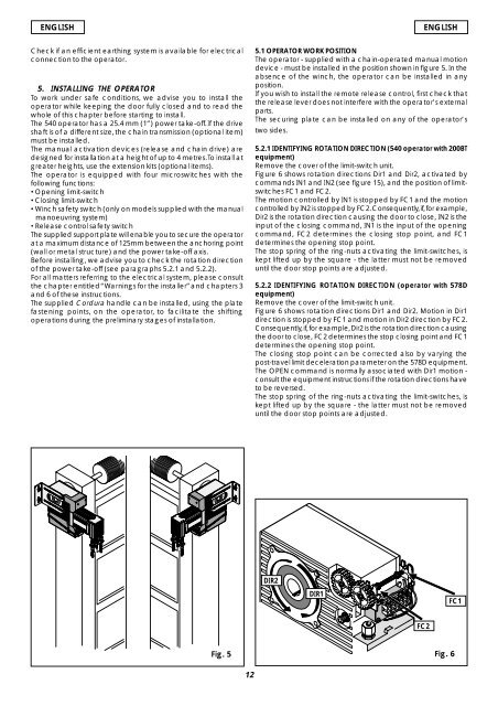
ENGLISHENGLISHCheck if an efficient earthing system is available for electricalconnection to the operator.5. INSTALLING THE OPERATORTo work under safe conditions, we advise you to install theoperator while keeping the door fully closed and to read thewhole of this chapter before starting to install.The 540 operator has a 25.4 mm (1”) power take-off. If the driveshaft is of a different size, the chain transmission (optional item)must be installed.The manual activation devices (release and chain drive) aredesigned for installation at a height of up to 4 metres. To install atgreater heights, use the extension kits (optional items).The operator is equipped with four microswitches with thefollowing functions:•Opening limit-switch•Closing limit-switch•Winch safety switch (only on models supplied with the manualmanoeuvring system)•Release control safety switchThe supplied support plate will enable you to secure the operatorat a maximum distance of 125mm between the anchoring point(wall or metal structure) and the power take-off axis.Before installing, we advise you to check the rotation directionof the power take-off (see paragraphs 5.2.1 and 5.2.2).For all matters referring to the electrical system, please consultthe chapter entitled “Warnings for the installer” and chapters 3and 6 of these instructions.The supplied Cordura handle can be installed, using the platefastening points, on the operator, to facilitate the shiftingoperations during the preliminary stages of installation.5.1 OPERATOR WORK POSITIONThe operator - supplied with a chain-operated manual motiondevice - must be installed in the position shown in figure 5. In theabsence of the winch, the operator can be installed in anyposition.If you wish to install the remote release control, first check thatthe release lever does not interfere with the operator’s externalparts.The securing plate can be installed on any of the operator’stwo sides.5.2.1 IDENTIFYING ROTATION DIRECTION (540 operator with 200BTequipment)Remove the cover of the limit-switch unit.Figure 6 shows rotation directions Dir1 and Dir2, activated bycommands IN1 and IN2 (see figure 15), and the position of limitswitchesFC1 and FC2.The motion controlled by IN1 is stopped by FC1 and the motioncontrolled by IN2 is stopped by FC2. Consequently, if, for example,Dir2 is the rotation direction causing the door to close, IN2 is theinput of the closing command, IN1 is the input of the openingcommand, FC2 determines the closing stop point, and FC1determines the opening stop point.The stop spring of the ring-nuts activating the limit-switches, iskept lifted up by the square - the latter must not be removeduntil the door stop points are adjusted.5.2.2 IDENTIFYING ROTATION DIRECTION (operator with 578Dequipment)Remove the cover of the limit-switch unit.Figure 6 shows rotation directions Dir1 and Dir2. Motion in Dir1direction is stopped by FC1 and motion in Dir2 direction by FC2.Consequently, if, for example, Dir2 is the rotation direction causingthe door to close, FC2 determines the stop closing point and FC1determines the opening stop point.The closing stop point can be corrected also by varying thepost-travel limit deceleration parameter on the 578D equipment.The OPEN command is normally associated with Dir1 motion -consult the equipment instructions if the rotation directions haveto be reversed.The stop spring of the ring-nuts activating the limit-switches, iskept lifted up by the square - the latter must not be removeduntil the door stop points are adjusted.DIR2DIR1FC1FC2Fig. 5 Fig. 612