Wake topology and hydrodynamic performance of low-aspect-ratio ...
Wake topology and hydrodynamic performance of low-aspect-ratio ...
Wake topology and hydrodynamic performance of low-aspect-ratio ...

Create successful ePaper yourself
Turn your PDF publications into a flip-book with our unique Google optimized e-Paper software.
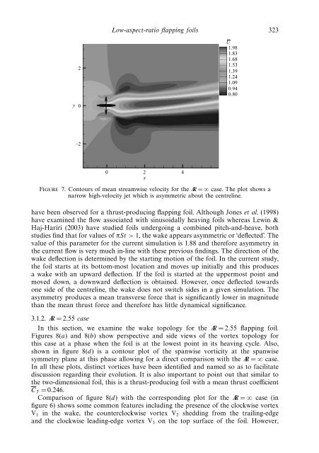
Low-<strong>aspect</strong>-<strong>ratio</strong> flapping foils 3232U1.981.831.681.531.391.241.090.940.80y0–20 2 4xFigure 7. Contours <strong>of</strong> mean streamwise velocity for the AR = ∞ case. The plot shows anarrow high-velocity jet which is asymmetric about the centreline.have been observed for a thrust-producing flapping foil. Although Jones et al. (1998)have examined the f<strong>low</strong> associated with sinusoidally heaving foils whereas Lewin &Haj-Hariri (2003) have studied foils undergoing a combined pitch-<strong>and</strong>-heave, bothstudies find that for values <strong>of</strong> πSt > 1, the wake appears asymmetric or ‘deflected’. Thevalue <strong>of</strong> this parameter for the current simulation is 1.88 <strong>and</strong> therefore asymmetry inthe current f<strong>low</strong> is very much in-line with these previous findings. The direction <strong>of</strong> thewake deflection is determined by the starting motion <strong>of</strong> the foil. In the current study,the foil starts at its bottom-most location <strong>and</strong> moves up initially <strong>and</strong> this producesa wake with an upward deflection. If the foil is started at the uppermost point <strong>and</strong>moved down, a downward deflection is obtained. However, once deflected towardsone side <strong>of</strong> the centreline, the wake does not switch sides in a given simulation. Theasymmetry produces a mean transverse force that is significantly <strong>low</strong>er in magnitudethan the mean thrust force <strong>and</strong> therefore has little dynamical significance.3.1.2. AR =2.55 caseIn this section, we examine the wake <strong>topology</strong> for the AR =2.55 flapping foil.Figures 8(a) <strong>and</strong>8(b) show perspective <strong>and</strong> side views <strong>of</strong> the vortex <strong>topology</strong> forthis case at a phase when the foil is at the <strong>low</strong>est point in its heaving cycle. Also,shown in figure 8(d) is a contour plot <strong>of</strong> the spanwise vorticity at the spanwisesymmetry plane at this phase al<strong>low</strong>ing for a direct comparison with the AR = ∞ case.In all these plots, distinct vortices have been identified <strong>and</strong> named so as to facilitatediscussion regarding their evolution. It is also important to point out that similar tothe two-dimensional foil, this is a thrust-producing foil with a mean thrust coefficientC T =0.246.Comparison <strong>of</strong> figure 8(d) with the corresponding plot for the AR = ∞ case (infigure 6) shows some common features including the presence <strong>of</strong> the clockwise vortexV 1 in the wake, the counterclockwise vortex V 2 shedding from the trailing-edge<strong>and</strong> the clockwise leading-edge vortex V 3 on the top surface <strong>of</strong> the foil. However,