338 H. Dong, R. Mittal <strong>and</strong> F. M. Najjar(a)4(C T ) AR=2.55 /(C T ) AR=1.27(b) 4(η) AR=2.55 /(η) AR=1.27(C T ) AR=5.09 /(C T ) AR=2.55St(η) AR=5.09 /(η) AR=2.55Thrust <strong>ratio</strong>32Efficiency <strong>ratio</strong>32110.6 0.8 1.0 1.2St0.6 0.8 1.0 1.2Figure 23. Relative increase in <strong>hydrodynamic</strong> <strong>performance</strong> with <strong>aspect</strong>-<strong>ratio</strong>. (a) Thrustcoefficient, (b) efficiency. The Reynolds number is 200 for all these cases.maximum at an intermediate value <strong>of</strong> Strouhal number. Furthermore, the Strouhalnumber at which this peak occurs decreases with increasing <strong>aspect</strong> <strong>ratio</strong>. For the twodimensionalinfinite-<strong>aspect</strong>-<strong>ratio</strong> case, the maximum is reached at a Strouhal number<strong>of</strong> about 0.53, whereas the corresponding values <strong>of</strong> the AR =5.09, 2.55 <strong>and</strong> 1.27 casesare 0.55, 0.75 <strong>and</strong> 0.83, respectively. It is also observed that the maximum efficiencyincreases with <strong>aspect</strong> <strong>ratio</strong>. However, at Strouhal numbers higher than about 0.85,all the cases except for the AR =1.27 cases show virtually the same efficiency values.Thus, except for very small <strong>aspect</strong>-<strong>ratio</strong> fins, efficiencies comparable to those <strong>of</strong> ainfinite <strong>aspect</strong>-<strong>ratio</strong> fin can be attained for higher Strouhal numbers. This wouldimply that <strong>low</strong>-<strong>aspect</strong>-<strong>ratio</strong> pectoral fins that are used for paddling as well as flappingcan match the thrust efficiency <strong>of</strong> high-<strong>aspect</strong>-<strong>ratio</strong> fins in the flapping mode onlyif the <strong>aspect</strong> <strong>ratio</strong> is above a certain minimum value <strong>and</strong> if the fin is operated atrelatively high Strouhal numbers. The optimal Strouhal numbers found in the currentstudy are higher than the range usually considered optimal for swimming <strong>and</strong> flyinganimals (Taylor, Nudds & Thomas 2003; Rohr & Fish 2004). This is probably due tothe particular choice <strong>of</strong> parameters (amplitude, maximum pitch angle <strong>and</strong> Reynoldsnumber) in the current study. As mentioned earlier, the relatively <strong>low</strong> Reynoldsnumber in the current study leads to a proportionately large shear drag that has tobe overcome in order for the foil to produce net thrust. This tends to push optimalStrouhal numbers to higher values. Also, Hover et al. (2004) find that even at highReynolds numbers, depending on the maximum angle-<strong>of</strong>-attack, the optimal Strouhalnumbers can vary from 0.3 to 0.6 for a rigid flapping foil. Thus, the optimal Strouhalnumber can vary over a fairly large range with some <strong>of</strong> these parameters.Figure 23 presents the relative increase in the thrust <strong>and</strong> efficiency with <strong>aspect</strong> rati<strong>of</strong>or a range <strong>of</strong> Strouhal numbers. Essentially, we compare the relative increase in thrust<strong>and</strong> efficiency as the <strong>aspect</strong> <strong>ratio</strong> doubles from 1.27 to 2.55 with the correspondingincrease as the <strong>aspect</strong> <strong>ratio</strong> again doubles from 2.55 to 5.09. Values corresponding toSt =0.4 are not included in these plots since some <strong>of</strong> the thrust <strong>and</strong> efficiency valuesare close to zero for this Strouhal number <strong>and</strong> this can give unrealistic values <strong>of</strong> therelative increase. The plots show that for all Strouhal numbers, the gain in thrust<strong>and</strong> efficiency in going from AR =1.27 to 2.55 is larger than the corresponding gainin going from AR =2.55 to 5.09. In fact, at the <strong>low</strong>er end <strong>of</strong> the Strouhal numberrange, the difference is quite dramatic. For instance, at St =0.6 the thrust coefficient
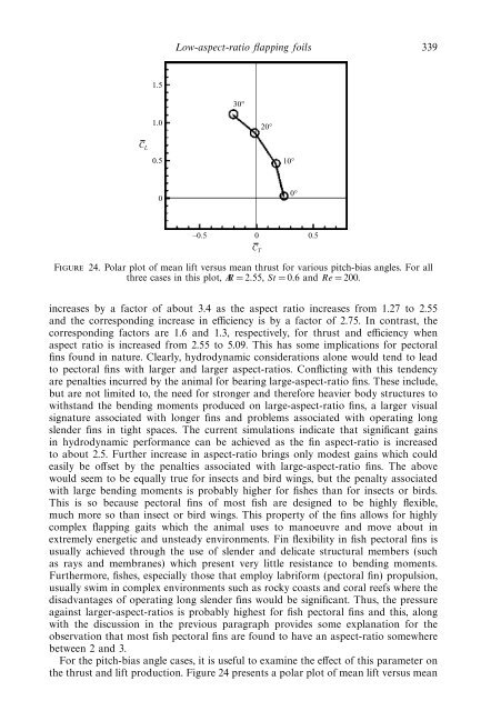
Low-<strong>aspect</strong>-<strong>ratio</strong> flapping foils 3391.530°1.020°C L0.510°00°–0.5 0 0.5Figure 24. Polar plot <strong>of</strong> mean lift versus mean thrust for various pitch-bias angles. For allthree cases in this plot, AR =2.55, St =0.6 <strong>and</strong>Re = 200.C Tincreases by a factor <strong>of</strong> about 3.4 as the <strong>aspect</strong> <strong>ratio</strong> increases from 1.27 to 2.55<strong>and</strong> the corresponding increase in efficiency is by a factor <strong>of</strong> 2.75. In contrast, thecorresponding factors are 1.6 <strong>and</strong> 1.3, respectively, for thrust <strong>and</strong> efficiency when<strong>aspect</strong> <strong>ratio</strong> is increased from 2.55 to 5.09. This has some implications for pectoralfins found in nature. Clearly, <strong>hydrodynamic</strong> conside<strong>ratio</strong>ns alone would tend to leadto pectoral fins with larger <strong>and</strong> larger <strong>aspect</strong>-<strong>ratio</strong>s. Conflicting with this tendencyare penalties incurred by the animal for bearing large-<strong>aspect</strong>-<strong>ratio</strong> fins. These include,but are not limited to, the need for stronger <strong>and</strong> therefore heavier body structures towithst<strong>and</strong> the bending moments produced on large-<strong>aspect</strong>-<strong>ratio</strong> fins, a larger visualsignature associated with longer fins <strong>and</strong> problems associated with operating longslender fins in tight spaces. The current simulations indicate that significant gainsin <strong>hydrodynamic</strong> <strong>performance</strong> can be achieved as the fin <strong>aspect</strong>-<strong>ratio</strong> is increasedto about 2.5. Further increase in <strong>aspect</strong>-<strong>ratio</strong> brings only modest gains which couldeasily be <strong>of</strong>fset by the penalties associated with large-<strong>aspect</strong>-<strong>ratio</strong> fins. The abovewould seem to be equally true for insects <strong>and</strong> bird wings, but the penalty associatedwith large bending moments is probably higher for fishes than for insects or birds.This is so because pectoral fins <strong>of</strong> most fish are designed to be highly flexible,much more so than insect or bird wings. This property <strong>of</strong> the fins al<strong>low</strong>s for highlycomplex flapping gaits which the animal uses to manoeuvre <strong>and</strong> move about inextremely energetic <strong>and</strong> unsteady environments. Fin flexibility in fish pectoral fins isusually achieved through the use <strong>of</strong> slender <strong>and</strong> delicate structural members (suchas rays <strong>and</strong> membranes) which present very little resistance to bending moments.Furthermore, fishes, especially those that employ labriform (pectoral fin) propulsion,usually swim in complex environments such as rocky coasts <strong>and</strong> coral reefs where thedisadvantages <strong>of</strong> operating long slender fins would be significant. Thus, the pressureagainst larger-<strong>aspect</strong>-<strong>ratio</strong>s is probably highest for fish pectoral fins <strong>and</strong> this, alongwith the discussion in the previous paragraph provides some explanation for theobservation that most fish pectoral fins are found to have an <strong>aspect</strong>-<strong>ratio</strong> somewherebetween 2 <strong>and</strong> 3.For the pitch-bias angle cases, it is useful to examine the effect <strong>of</strong> this parameter onthe thrust <strong>and</strong> lift production. Figure 24 presents a polar plot <strong>of</strong> mean lift versus mean
- Page 12 and 13: 320 H. Dong, R. Mittal and F. M. Na
- Page 14 and 15: 322 H. Dong, R. Mittal and F. M. Na
- Page 16 and 17: 324 H. Dong, R. Mittal and F. M. Na
- Page 18 and 19: 326 H. Dong, R. Mittal and F. M. Na
- Page 20 and 21: 328 H. Dong, R. Mittal and F. M. Na
- Page 22 and 23: 330 H. Dong, R. Mittal and F. M. Na
- Page 24 and 25: 332 H. Dong, R. Mittal and F. M. Na
- Page 26 and 27: 334 H. Dong, R. Mittal and F. M. Na
- Page 28 and 29: 336 H. Dong, R. Mittal and F. M. Na
- Page 32 and 33: 340 H. Dong, R. Mittal and F. M. Na
- Page 34 and 35: 342 H. Dong, R. Mittal and F. M. Na