Optical implementation of propagation-invariant pulsed free ... - Tartu
Optical implementation of propagation-invariant pulsed free ... - Tartu
Optical implementation of propagation-invariant pulsed free ... - Tartu

Create successful ePaper yourself
Turn your PDF publications into a flip-book with our unique Google optimized e-Paper software.
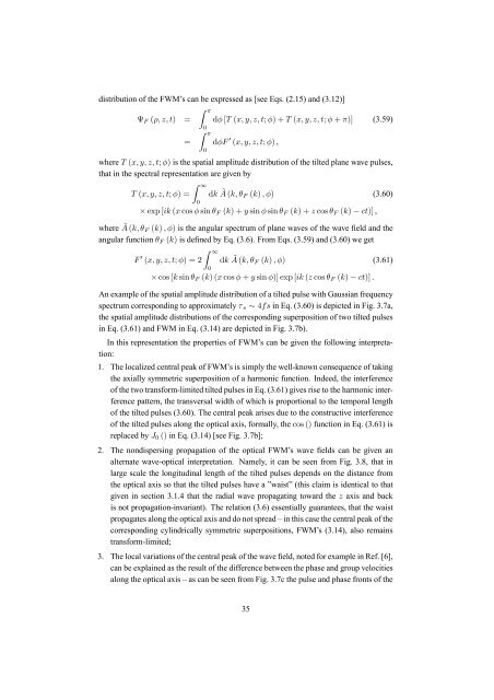
distribution <strong>of</strong> the FWM’s can be expressed as [see Eqs. (2.15) and (3.12)]Ψ F (ρ, z, t) ==Z π0Z π0dφ [T (x, y, z, t; φ)+T (x, y, z, t; φ + π)] (3.59)dφF 0 (x, y, z, t; φ) ,where T (x, y, z, t; φ) is the spatial amplitude distribution <strong>of</strong> the tilted plane wave pulses,that in the spectral representation are given byT (x, y, z, t; φ) =Z ∞0dk à (k, θ F (k) ,φ) (3.60)× exp [ik (x cos φ sin θ F (k)+y sin φ sin θ F (k)+z cos θ F (k) − ct)] ,where à (k, θ F (k) ,φ) is the angular spectrum <strong>of</strong> plane waves <strong>of</strong> the wave field and theangular function θ F (k) is defined by Eq. (3.6). From Eqs. (3.59) and (3.60) we getF 0 (x, y, z, t; φ) =2Z ∞0dk à (k, θ F (k) ,φ) (3.61)× cos [k sin θ F (k)(x cos φ + y sin φ)] exp [ik (z cos θ F (k) − ct)] .An example <strong>of</strong> the spatial amplitude distribution <strong>of</strong> a tilted pulse with Gaussian frequencyspectrum corresponding to approximately τ s ∼ 4fs in Eq. (3.60) is depicted in Fig. 3.7a,the spatial amplitude distributions <strong>of</strong> the corresponding superposition <strong>of</strong> two tilted pulsesin Eq. (3.61) and FWM in Eq. (3.14) are depicted in Fig. 3.7b).In this representation the properties <strong>of</strong> FWM’s can be given the following interpretation:1. The localized central peak <strong>of</strong> FWM’s is simply the well-known consequence <strong>of</strong> takingthe axially symmetric superposition <strong>of</strong> a harmonic function. Indeed, the interference<strong>of</strong> the two transform-limited tilted pulses in Eq. (3.61) gives rise to the harmonic interferencepattern, the transversal width <strong>of</strong> which is proportional to the temporal length<strong>of</strong> the tilted pulses (3.60). The central peak arises due to the constructive interference<strong>of</strong> the tilted pulses along the optical axis, formally, the cos () function in Eq. (3.61) isreplaced by J 0 () in Eq. (3.14) [see Fig. 3.7b];2. The nondispersing <strong>propagation</strong> <strong>of</strong> the optical FWM’s wave fields can be given analternate wave-optical interpretation. Namely, it can be seen from Fig. 3.8, that inlarge scale the longitudinal length <strong>of</strong> the tilted pulses depends on the distance fromthe optical axis so that the tilted pulses have a ”waist” (this claim is identical to thatgiven in section 3.1.4 that the radial wave propagating toward the z axis and backis not <strong>propagation</strong>-<strong>invariant</strong>). The relation (3.6) essentially guarantees, that the waistpropagates along the optical axis and do not spread – in this case the central peak <strong>of</strong> thecorresponding cylindrically symmetric superpositions, FWM’s (3.14), also remainstransform-limited;3. The local variations <strong>of</strong> the central peak <strong>of</strong> the wave field, noted for example in Ref. [6],can be explained as the result <strong>of</strong> the difference between the phase and group velocitiesalong the optical axis – as can be seen from Fig. 3.7c the pulse and phase fronts <strong>of</strong> the35