PH-20/PHX-20 Proportioner - Spray Foam Equipment
PH-20/PHX-20 Proportioner - Spray Foam Equipment
PH-20/PHX-20 Proportioner - Spray Foam Equipment

Create successful ePaper yourself
Turn your PDF publications into a flip-book with our unique Google optimized e-Paper software.
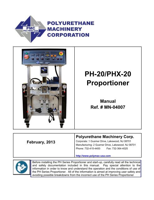
<strong>PH</strong>-<strong>20</strong>/<strong>PH</strong>X-<strong>20</strong><strong>Proportioner</strong>ManualRef. # MN-04007February, <strong>20</strong>13Polyurethane Machinery Corp.Corporate: 1 Gusmer Drive, Lakewood, NJ 08701Manufacturing: 2 Gusmer Drive, Lakewood, NJ 08701Phone: 732-415-4400 Fax: 732-364-4025http://www.polymac-usa.comBefore installing the <strong>PH</strong> Series <strong>Proportioner</strong> and start-up, carefully read all the technicaland safety documentation included in this manual. Pay special attention to theinformation in order to know and understand the operation and the conditions of use ofthe <strong>PH</strong> Series <strong>Proportioner</strong>. All of the information is aimed at improving user safety andavoiding possible breakdowns from the incorrect use of the <strong>PH</strong> Series <strong>Proportioner</strong>
<strong>PH</strong>-<strong>20</strong>/<strong>PH</strong>X-<strong>20</strong> ManualWarranty ……………………………………………………………………………………….. 3Safety and Handling …………………………………………………………………………. 5CharacteristicsPrincipal Heating System …………………………………………………………………. 7Hose Heating System ……………………………………………………………………… 7Double Acting Piston Metering Pumps …………………………………………………… 7Technical SpecificationsElectrical ……………………………………………………………………………………… 8Mechanical …………………………………………………………………………………… 8Description ……………………………………………………………………………………… 9Installation ………………………………………………………………………………………. 14<strong>Proportioner</strong> Purging………………………………………………………………………….. <strong>20</strong>Digital Temperature Controller………………………………………………………………. 22Start-Up ……………………………………………………………………….......................... 23Shutdown Procedures ………………………………………………………………………. 25Troubleshooting ……………………………………………………………………………… 26Heaters ……………………………………………………………………………………… 27Hydraulic Drive System……………………………………………………………………. 30Metering Pump Line………………………………………………………………………... 33Hose Heating ……………………………………………………………………………….. 37Maintenance …………………………………………………………………………………… 41Inlet Material Screens ……………………………………………………………………… 42Hydraulic Drive System ……………………………………………………………………. 43Metering Pump Line ………………………………………………………………………… 44Material Heater ……………………………………………………………………………… 45Hydraulic Oil Specification …………………………………………………………………... 47Parts Identification …………………………………………………………………..………… 46Replacement Kits ……………..………..…………………………………………………… 48Machine Spare Parts ………..…………………………………..………..………………… 49Hoses ………………………………………………………………………………………… 52<strong>PH</strong>X<strong>20</strong>, 3000 PSI Pump Line-61-…………………………..………..………………....... 54<strong>PH</strong>-<strong>20</strong>, <strong>20</strong>00 PSI Pump Line-123…………………………………………………………. 56Electrical Parts………………………………………………………………………………. 58Electrical Schematics……………………………………………………………………….. 622
<strong>PH</strong>-<strong>20</strong>/<strong>PH</strong>X-<strong>20</strong> ManualWARRANTYPolyurethane Machinery Corporation (hereinafter “PMC”) provides this LIMITED WARRANTY(hereinafter “Warranty”) to the original purchaser (hereinafter “Customer”) covering this equipment andthe original PMC manufactured accessories delivered with the equipment (hereinafter “Product”)against defects in material or workmanship of the Product (hereinafter “Defect” or “Defective”) for aperiod of one (1) year from the date of first purchase as shown on the original PMC invoice (hereinafter“Warranty Period”).If during the Warranty Period under normal use, the Product is suspected by Customer to be Defectivein material or workmanship, it is Customer’s responsibility to contact PMC and return the Product toPMC as directed by PMC, freight prepaid. If PMC determines that the Product is Defective and thatsuch Defect is covered by this Warranty, PMC will credit Customer for the reasonable freight chargesincurred by Customer in returning the Defective Product to PMC, and PMC (or its authorized agent)will, at PMC’s option, repair or replace the Product, subject to the following:Original Invoice: The original invoice must be kept as proof of the date of first sale and the Productserial number. The Warranty does not cover any Product if the Original Invoice appears to have beenmodified or altered, or when the serial number on the Product appears to have been altered ordefaced.Product Maintenance: It is the Customer’s responsibility to maintain the Product properly. See yourmaintenance schedule and owner’s manual for details. The Warranty does not cover an improperlymaintained Product.Non-PMC Components and Accessories: Non-PMC manufactured components and accessories thatare used in the operation of the Product are not covered by this Warranty. Such components andaccessories shall be subject to the warranty offered to the Customer, if any, by the originalmanufacturer of such component or accessory.Other Warranty Exclusions: The Warranty does not cover any Product that PMC determines has beendamaged or fails to operate properly due to misuse, negligence, abuse, carelessness, neglect, oraccident. By way of example only, this includes:Normal wear and tear.Improper or unauthorized installation, repair, alteration, adjustment or modification of theProduct.Use of heating devices, pumping equipment, dispensers, or other parts or accessories with theProduct that have not been approved or manufactured by PMC.Failure to follow the operating instructions and recommendations provided by PMC.Cosmetic damage.Fire, flood, “acts of God,” or other contingencies beyond the control of PMC.3
<strong>PH</strong>-<strong>20</strong>/<strong>PH</strong>X-<strong>20</strong> ManualWARRANTY (cont’d)THE WARRANTY DESCRIBED HEREIN IS THE EXCLUSIVE REMEDY FOR THECUSTOMER AND IS IN LIEU OF ALL OTHER WARRANTIES, EXPRESS, IMPLIED,STATUTORY OR OTHERWISE, AND THE IMPLIED WARRANTIES OFMERCHANTABILITY AND FITNESS FOR A PARTICULAR PURPOSE AND ALL OTHERWARRANTIES ARE HEREBY DISCLAIMED. TO THE FULLEST EXTENT PERMITTED BYLAW, PMC SHALL NOT BE RESPONSIBLE, WHETHER BASED IN CONTRACT, TORT(INCLUDING, WITHOUT LIMITATION, NEGLIGENCE), WARRANTY OR ANY OTHERLEGAL OR EQUITABLE GROUNDS, FOR ANY CONSEQUENTIAL, INDIRECT,INCIDENTAL, LOST PROFITS, SPECIAL, PUNITIVE OR EXEMPLARY DAMAGES,WHETHER TO PERSON OR PROPERTY, ARISING FROM OR RELATING TO THEPRODUCT, EVEN IF PMC HAS BEEN ADVISED OF THE POSSIBILITY OF SUCH LOSSESOR DAMAGES.Non-Warranty Service by PMC: If PMC determines that the suspected Defect of the Product is notcovered by this Warranty, disposition of the Product will be made pursuant to the terms and conditionsof PMC’s written estimate on a time and materials basis.Continuing Warranty for Products Repaired or Replaced under Warranty: Following the repair orreplacement of a Product covered by this Warranty, such Product will continue to be subject to theoriginal Warranty for the remainder of original Warranty Period or for three (3) months from the repairor replacement date, whichever is longer.No Rights Implied: Nothing in the sale, lease or rental of any Product by PMC shall be construed togrant any right, interest or license in or under any patent, trademark, copyright, trade secret or otherproprietary right or material owned by anyone; nor does PMC encourage the infringement of same.Exclusive Warranty: This writing is the final, complete, and exclusive expression of the Warrantycovering the Product. Any statements made by PMC, its employees or agents that differ from theterms of this Warranty shall have no effect. It is expressly understood that Customer’s acceptance ofthis Warranty, by performance or otherwise, is upon and subject solely to the terms and conditionshereof, and any additional or different terms and conditions proposed or expressed by Customer oranyone, whether in writing or otherwise, are null and void unless specifically agreed to in writing by anOfficer of PMC.4
SAFETY AND HANDLING<strong>PH</strong>-<strong>20</strong>/<strong>PH</strong>X-<strong>20</strong> ManualThis chapter contains important information on the safety, handling and use of your Classic<strong>PH</strong> Series <strong>Proportioner</strong>.Before installing the <strong>PH</strong> Series <strong>Proportioner</strong> and start-up,carefully read all the technical and safety documentationincluded in this manual. Pay special attention to theinformation to know and understand the operation and theconditions of use of the <strong>PH</strong> Series <strong>Proportioner</strong>. All of theinformation is aimed at enhancing User Safety and avoidingpossible breakdowns derived from the incorrect use of the <strong>PH</strong>Series <strong>Proportioner</strong>.WARNING! presents information to alert of a situation that might cause seriousinjuries if the instructions are not followed.CAUTION! presents information that indicates how to avoid damage to the<strong>Proportioner</strong> or how to avoid a situation that could cause minor injuries.NOTE! is relevant information of a procedure being carried out.Careful study of this manual will enable the operator to know the characteristics of the <strong>PH</strong>Series <strong>Proportioner</strong> and the operating procedures. By following the instructions andrecommendations contained herein, you will reduce the potential risk of accidents in theinstallation, use or maintenance of the <strong>PH</strong> Series <strong>Proportioner</strong>; you will provide a betteropportunity for incident-free operation for a longer time, greater output and the possibility ofdetecting and resolving problems fast and simply.Keep this Operations Manual for future consultation of useful information at all times. If youlose this manual, ask for a new copy from your PMC Service Center, directly contact PMC oron line at our web site (www.polymac-usa.com).5
<strong>PH</strong>-<strong>20</strong>/<strong>PH</strong>X-<strong>20</strong> ManualSAFETY AND HANDLING (cont’d)The <strong>PH</strong> Series <strong>Proportioner</strong> has been designed and built for the application of polyurea chemicalsystems, polyurethane foam chemical systems and some two-component epoxy systems.WARNING! The design and configuration of the <strong>PH</strong> Series <strong>Proportioner</strong> does notallow its use in potentially explosive atmospheres or the pressure andtemperature limits described in the technical specifications of this manual to beexceeded.Always use liquids and solvents that are compatible with the unit. If in doubt, consult PMC TechnicalService.When working with the <strong>PH</strong> Series <strong>Proportioner</strong>, it is recommended that the operator wear suitableclothing and elements of personal protection, including, without limitation, gloves, protective goggles,safety footwear and face masks. Use breathing equipment when working with the <strong>PH</strong> Series<strong>Proportioner</strong> in enclosed spaces or in areas with insufficient ventilation. The introduction and follow-upof safety measures must not be limited to those described in this manual. Before starting up the <strong>PH</strong>Series <strong>Proportioner</strong>, a comprehensive analysis must be made of the risks derived from the products tobe dispensed, the type of application and the working environment.To prevent possible injury caused by incorrect handling of the rawmaterials and solvents used in the process, carefully read the MaterialSafety Data Sheet (MSDS)provided by your supplier.Deal with the waste caused according to current regulations.To avoid damage caused by the impact of pressurized fluids, do not openany connection or perform maintenance work on components subject topressure until the pressure has been completely eliminated.Use suitable protection when operating, maintaining or being present inthe area where the equipment is functioning. This includes, but is notlimited to, the use of protective goggles, gloves, shoes and safety clothingand breathing equipment.The equipment includes components that reach high temperatures and cancause burns. Hot parts of the equipment must not be handled or toucheduntil they have cooled completely.To prevent serious injury through crushing or amputation, do not workwith the equipment without the safety guards installed on the movingparts. Make sure that all the safety guards are correctly reinstalled at theend of the repair or maintenance work of the equipment6
<strong>PH</strong>-<strong>20</strong>/<strong>PH</strong>X-<strong>20</strong> ManualCHARACTERISTICSThe <strong>PH</strong>-<strong>20</strong>/PAX-<strong>20</strong> <strong>Proportioner</strong> has been designed and built for the application of polyureachemical systems, polyurethane foam chemical systems and some specific two-componentepoxy systems.Principal Heating SystemThe <strong>Proportioner</strong>s consists of two (2) independent Material Heaters without internal seals. The<strong>PH</strong>-<strong>20</strong> Heater has Three (3) Heating Elements per heater rated at 1,250 watts each giving the<strong>Proportioner</strong> a total heat of 7500 watts. The <strong>PH</strong>X-30 heater also has 3 Heating elements perheater rated at 1500 watts each giving the proportioner a total heat of 9000 watts. Each heaterhas the necessary controls and safety components for their precise operation. The MaterialHeater design allows a temperature differential (ΔT) of 58º F and material applicationtemperatures of up to 190º F.Hose Heating SystemThe system is designed with a 2 KVA Isolation Transformer that enables effective heating ofup to a total hose length of 210 feet. The system includes an innovative hose heating conceptin which the continuous braid tinned-copper jacket is distributed evenly around thecircumference of the hose providing a uniform heating watt density and precise control of thematerial application temperature. This hose heating element design is extremely resistant tofatigue failure.100% circumferential coverage produces themost uniform distribution of heat available.Double Acting Piston Metering PumpsThe vertical double acting Pump Line is driven by a Hydraulic Cylinder. The in-line pumpsystem with vertical piston pumps provides a constant volume and ratio on both the up strokeand down stroke. .7
<strong>PH</strong>-<strong>20</strong>/<strong>PH</strong>X-<strong>20</strong> ManualTECHNICAL SPECIFICATIONSElectricalMain Voltage: ______________________________________ 3 x <strong>20</strong>8-230V, 50/60HzElectrical Consumption: <strong>PH</strong>-<strong>20</strong>, <strong>20</strong>00 PSI (2 x 3.75 kW Heaters) ___ 27 A @ 3 x 230VElectrical Consumption: <strong>PH</strong>X-<strong>20</strong>, 3000 PSI (2 x 4.5 kW Heaters) ____32 A @ 3 x 230VMain Voltage: ________________________________________ 1 x <strong>20</strong>8-230V, 50/60HzElectrical Consumption: <strong>PH</strong>-<strong>20</strong>, <strong>20</strong>00 PSI (2 x 3.75 kW Heaters) _____ 58 A @ 1 x 230VElectrical Consumption: <strong>PH</strong>X-<strong>20</strong>, 3000 PSI (2 x 4.5 kW Heaters) _____ 65 A @ 1 x 230VMaterial Heater Power: <strong>PH</strong>-<strong>20</strong> (2 x 3.75 kW) ______________________________ 7.5 kWMaterial Heater Power: <strong>PH</strong>X-<strong>20</strong> (2 x 4.5 kW) ______________________________ 9 kWHose Transformer Power: ___________________________________________ 2 KVAElectrical Motor Power: ________________________________________________ 3 hpCAUTION! Inside the console, is a Terminal Strip for connectingthe main power (wire not supplied) to the <strong>PH</strong> Series<strong>Proportioner</strong>. This electrical connection must be made only bya qualified electrician.MechanicalMaximum working pressure <strong>PH</strong>-<strong>20</strong> (with 123 pumps): ______________________ 2,000 psiMaximum working pressure <strong>PH</strong>X-<strong>20</strong> (with 61 pumps): _____________________ 3,000 psiMaximum production ratio 1:1 <strong>PH</strong>-<strong>20</strong> (with 123 pumps): ____________________ <strong>20</strong> lb/minMaximum production ratio 1:1 <strong>PH</strong>X-<strong>20</strong> (with 61 pumps): _____________________ 1.3 gpmMinimum production: ________________________________________________ 2 lb/minMaximum hose length: _________________________________________________ 210 ftApproximate weight (Hydraulic Tank empty): ______________________________ 365 lbsApproximate weight (Hydraulic Tank full @ 12 gal): _________________________ 435 lbsDimensions: __________________________________________ 30in W x 26in D x 45in H8
<strong>PH</strong>-<strong>20</strong>/<strong>PH</strong>X-<strong>20</strong> ManualDESCRIPTIONAAAHKJMDBCEOO<strong>PH</strong>-<strong>20</strong>/<strong>PH</strong>X-<strong>20</strong> <strong>Proportioner</strong>sA. Control PanelControls and regulates the operation of the <strong>PH</strong> Series <strong>Proportioner</strong>.B. Isocyanate (Iso, A) Metering PumpMeters the Isocyanate material.C. Polyol (Poly, R) Metering PumpMeters the Polyol material.D. Isocyanate (Iso, A) HeaterHeats the incoming Isocyanate to a temperature set by the operator.E. Polyol (Poly, R) HeaterHeats the incoming Polyol to a temperature set by the operator.9
<strong>PH</strong>-<strong>20</strong>/<strong>PH</strong>X-<strong>20</strong> ManualF. Hose Heating Transformer – Right side, inside of hydraulic tankSupplies the required voltage for material Heated Hoses.FG. Hydraulic Pressure GageIndicates the pressure in the Hydraulic Drive System.H. Isocyanate (Iso, A) Pressure GageIndicates the pressure in the Isocyanate system.I. Isocyanate (Iso, A) Safety Pressure SwitchTurns OFF the Directional Valve in the event of excessive pressure in the Isocyanatesystem.J. Isocyanate (Iso, A) ThermocoupleProvides temperature information of the Isocyanate to its Temperature Controller.K. Polyol (Poly, R) Pressure GageIndicates the pressure in the Polyol system.L. Polyol (Poly, R) Safety Pressure SwitchTurns OFF the Directional Valve in the event of excessive pressure in the Polyol system.M. Polyol (Poly, R) ThermocoupleProvides temperature information of the Polyol to its Temperature Controller.N. Hydraulic Pressure ControlAllows the pressure of the hydraulic system to be increased or decreased. Turnclockwise to increase the pressure and counterclockwise to decrease. To regulate thepressure of the hydraulic system, the NORMAL or RETRACT Pump Switch positionmust be selected.NLIG10
<strong>PH</strong>-<strong>20</strong>/<strong>PH</strong>X-<strong>20</strong> ManualO. Inlet Material StrainerScreens (60 mesh) material from bulk supply.11
<strong>PH</strong>-<strong>20</strong>/<strong>PH</strong>X-<strong>20</strong> ManualDESCRIPTION (cont’d)Figure 3T T TUWZQPS S SVYXRControl PanelP. Main Power - Turns ON and OFF main power to the control panel. It must be turnedON for any operation to be performed with the unit. When turned ON, the red pilot willlight.Q. Emergency Stop - Interrupts the <strong>PH</strong>- Series control power circuit to stop all motionand heating.R. Control Power - Turns ON and OFF the control power to the complete electricalcircuit including Heaters and Hose Heater.S. Heater Temperature Switch - A (Iso), R (Poly), HOSE - Turns ON and OFF powerto the specific Heaters and Hose.T. Controllers – Displays the temperature of the chemicals. See page 22 for detailedTemperature Controller instructions.U. Totalizer – Indicates the number of pump cycles to calculate material usage.MODEL PUMP SIZE CYCLES PER GALLON<strong>PH</strong>-<strong>20</strong>, <strong>20</strong>00 PSI 123 23<strong>PH</strong>X-<strong>20</strong>, 3000 PSI 61 47V. Auto Shut Down Switch - Turns ON and OFF power to the Auto Shut Down unit.12
<strong>PH</strong>-<strong>20</strong>/<strong>PH</strong>X-<strong>20</strong> ManualW. Auto Shut Down CounterUsed to set the amount of cycles required to prevent the chemical drums from runningdry, the machine will shut down when the preset cycles expire. There is an on/offswitch to activate this feature or deactivate and not use it, see page 24.X. Motor Switch - Turns ON and OFF the Electric/Hydraulic Motor. When turned ON,the pilot will light. In the event of an overload of the Motor, pilot light will turn OFF andMotor will stop.Y. Pump SwitchOff - Removes power from the pump circuit. The directional indicator lights will not belit.Normal - Activates the normal operation of the machine. When the switch is ON, thedirectional light corresponding to the stroke direction will light.Retract - Sets the Piston Rod of the Iso (A) metering pump to the down position andprevents the crystallization of Iso (A) on the Piston Rod. Press the RETRACT keyevery time the unit is stopped by the operator (see Shut-Down, page 25).Z. Direction Indicator Light - Indicates the movement direction of the Metering Pumps.If excessive pressure is caused in the system, the pump circuit will be disabled and thedirectional lights will be OFF..13
INSTALLATION<strong>PH</strong>-<strong>20</strong>/<strong>PH</strong>X-<strong>20</strong> ManualWARNING! Use suitable protection and follow the recommendations in theSafety Information enclosed and provided by material suppliers when installingor working with the <strong>Proportioner</strong>.Inside the console is a Terminal Strip for connecting theincoming power cable (not supplied). The electrical connectionof the <strong>Proportioner</strong> must be carried out by a qualifiedelectrician.NOTE! To ensure the <strong>PH</strong>-<strong>20</strong> Series <strong>Proportioner</strong> works correctly, theelectrical supply must meet the specifications indicated on the Serial NumberPlacard affixed to the Electrical Console.CAUTION! Make sure the power cable is disconnected from the main powersource before connecting to the Terminal Strip in the Console.1 phase x 230 VoltL1L2L1L2L33 phase x 230 VoltFollow the recommended procedure in the indicated order to install the <strong>Proportioner</strong>:1. Insert the main power cable by passing it through the wire stop at the bottom of theElectrical Console and connect as shown in the above diagram.2. Fill the reservoir with the recommended hydraulic oil. To fill remove the screws fromthe tank cover and rotate the cover, be careful not to damage the gasket. See page47 for oil specifications.Tank cover14
<strong>PH</strong>-<strong>20</strong>/<strong>PH</strong>X-<strong>20</strong> ManualNOTE! Do not fill the tank to maximum capacity; Make sure the amountof hydraulic fluid is not more than 12 gal or 80% of the tank maximumcapacity.3. Check the level of the hydraulic fluid in the Hydraulic Pump Case: Disconnect theHydraulic Hose from the 90 fitting and remove Fitting from Hydraulic Case. Add fluidas required. Reattach Fitting and Hydraulic Hose. Turn the hydraulic pressure controlknob counter clockwise until it stops, that is the lowest hydraulic pressure setting.Check Fluid LevelHydraulic Pressure control Knob15
<strong>PH</strong>-<strong>20</strong>/<strong>PH</strong>X-<strong>20</strong> ManualINSTALLATION (cont’d)ENSURE THAT THE EMERGENCY (E-STOP) STOP IS NOT ENERGIZED4. Three-phase <strong>Proportioner</strong> Only: Check the Electric Motor to ensure rotation isclockwise. Remove the inspection cover from the motor bell housing whenviewing the end of the Electric Motor. A counter clockwise rotation indicates two of theincoming power leads need to be reversed.CAUTION! Ensure Main Power switch is OFF and incoming power is lockedOFF before reversing power leads.Recheck the rotation before proceeding with Installation (3 Phase only).Heated Hose InstallationCAUTION! The material delivery Heated Hoses are color coded Red andBlue allowing the user to recognize them. The Red corresponds to theIsocyanate (Iso, A) and the Blue to the Polyol (Poly, R). To avoid connectionerrors the Coupling Connections of the Iso (A) and Poly (R) Heated Hosesare also different sizes, which makes it difficult to swap connections.NOTE! The material delivery Heated Hoses are caped at the ends toprevent absorbing moisture. Do not remove caps until the Heated Hoses aregoing to be installed on the <strong>Proportioner</strong>.1. Lay out all the Heated Hose assemblies end to end aligning the Iso “A” (red) and Poly“R” (blue) and connect the respective Coupling Connections using the appropriatesized open-end wrench after ensuring Heated Hose assemblies lay flat.CAUTION! Take care to not cross-thread or over-tighten the CouplingConnections. Thread seal tape or compound is not required for this taperedseat Coupling Connections.2. Connect the material Heated Hoses to the outlets of the respective Heaters i.e. Iso (A)Heated Hose to the Iso (A) Heater and the Poly (R) Heated Hose to the Poly (R)Heater ensuring Heated Hose assemblies lay flat.3. Connect Air Hose Coupling Connections.16
<strong>PH</strong>-<strong>20</strong>/<strong>PH</strong>X-<strong>20</strong> ManualINSTALLATION (cont’d)Heated Hose Installation (cont’d)4. Connect the Heated Hose power wires to the “Fast-Lock”Connector coming from the Hose Heat Transformer as follows:a. Loosen the Socket Head Set Screw to allow insertion ofthe Heated Hose electrical wire Terminal.b. Insert the Terminal into the “Fast-Lock” Connector Body.c. Securely tighten the Socket Head Set Screw.d. Install electrical tape around Connector Body.Fast-Lock ConnectionNOTE! A good practice is to add some dielectric grease (Permatex 67VR orequivalent) to the outside of the Terminal prior to insertion.Repeat the above steps to connect the “Fast-Lock” Connectors that you will find on allHeated Hose power wire.CAUTION! Ensure the proper mechanical and electrical connections of theHeated Hoses are made to avoid possible material leakage and Hose heatproblems.5. It is recommended the TSU be installed between the last section of Heated Hose andthe Gun Whip. Carefully straighten the sensing wire, inserting it in the Iso (A) HeatedHose and tighten fluid fittings with appropriate sized open-end wrenches.CAUTION! To protect the TSU sensor, you must pay special attention not tokink or excessively bend the Heated Hoses. Do not coil the Heated Hoseswith a diameter of less than 4 feet.EL-51ATSU AssemblyEL-51A-2Sensor ReplacementCAUTION! Connecting the TSU between the first and second section ofHeated Hose results in the TSU sensing the material temperature exiting theHeater and not the inside of the Heated Hose near the <strong>Spray</strong> Gun.17
INSTALLATION (cont’d)<strong>PH</strong>-<strong>20</strong>/<strong>PH</strong>X-<strong>20</strong> ManualHose Heat TransformerThe Hose Heat Transformer offers the ability of connecting to different output voltagesdepending on the total length of the Heated Hose in use, maximizing the heating ability ofthe Heated Hose. The factory setting is 18 volts for use with 60 feet of Heated Hose.Before starting the <strong>Proportioner</strong>, ensure the setting matches the Heated Hose lengthinstalled. If Heated Hose sections are added or removed, the Tap setting should bechanged to a setting which will limit the maximum amperage in the Heated Hose to 52amps. The suggested settings are tabled below:Tap Length72v 210’54v 160’36v 110'18v 60’Hose HeaterTransformer6. Ensure the Manual Valves are CLOSED and connect the Coupling Block to the HeatedGun Whip.CAUTION! Excessive force closing or opening the Manual Valves may resultin damage to the Manual Valves and/or Coupling Block.7. Connect the Transfer Pump/ Heated Hose Assemblies/ Air Supply and Air Dryersystems as required. Review the Installation Instructions for each to ensure proper setupand operation.8. Install the Material Transfer Pumps as follows:WARNING! If Transfer Pumps have been previously used, pay specialattention to connect each Pump to “its” specific material. Inadvertentlychanging the Transfer Pumps will cause a chemical reaction rendering themuseless.18
<strong>PH</strong>-<strong>20</strong>/<strong>PH</strong>X-<strong>20</strong> ManualINSTALLATION (cont’d)NOTE! Placing a tape of the same color as of the Material Delivery Hoses (redfor the Iso (A), blue for the Poly (R)) on each Transfer Pump would be a goodmethod for minimizing errors in connection.a. Make sure that the Inlet Valves on the <strong>Proportioner</strong> are closed.b. Connect one end of the Polyol (R) Material Delivery Hose (¾” thread)to the <strong>Proportioner</strong> Polyol (R) Inlet Valve and the other end to thePolyol (R) Transfer Pump.c. Connect one end of the Iso (A) Material Delivery Hose (½” thread) to the<strong>Proportioner</strong> Iso (A) Inlet Valve and the other end to the Iso Transfer Pump.d. Connect the air hose to the Transfer Pumps after ensuring each Transfer PumpShut-Off Valve is CLOSED.NOTE! To avoid errors in connection, the Coupling connections of the Iso (A)and Poly (R) Material Delivery Hoses are different sizes, making it difficult toswap connections.e. Ground the Transfer Pump as recommend by the material supplier. The movementof product inside the Hoses can cause static electricity and produce electricaldischarges.f. Connect air to the air line coming off the first section of hose (90-110 psi).19
PROPORTIONER PURGING<strong>PH</strong>-<strong>20</strong>/<strong>PH</strong>X-<strong>20</strong> ManualWARNING! Use suitable Personal Protection <strong>Equipment</strong> (PPE) and followthe recommendations in the Safety Information provided by productsuppliers when installing or working with the unit.WARNING! Do not turn the Temperature Controllers ON until the<strong>Proportioner</strong> Purging procedure is complete and the Primary Heaters andHeated Hoses are filled with material.NOTE! Before using the <strong>Proportioner</strong> it is necessary to purge the entiresystem, including Heated Hoses of mineral oil left over from Quality Controltesting and air. The following procedure is also followed to purge airentrapped by running out of material in the supply Drum/Reservoirs resultingin a significant indicated material pressure imbalance as indicated by thePressure Gauges and sprayed material.1. Ensure the following before proceeding:a. Air supply to Transfer Pumps is 90 - 110 psi.b. <strong>Proportioner</strong> Inlet ball Valves are CLOSED.c. All connections are tight.d. Material should be stored to the material suppliers' recommended temperatures.e. <strong>Spray</strong> gun coupling block is installed.2. Slowly OPEN the Poly (R) Transfer Pump Air Shut-Off Valve allowing Pump to cycleslowly as it fills the Material Delivery Hose to the <strong>Proportioner</strong>. Check for leaks.3. OPEN Poly (R) Coupling Block Manual Valve over a waste container.4. Slowly OPEN <strong>Proportioner</strong> Poly (R) Inlet Valve allowing Transfer Pump to move materialthrough the system. When all spitting of air stops and all traces of mineral oil havedisappeared, CLOSE Poly (R) Coupling Block Manual Valve. Clean Coupling Block.5. Repeat steps 2 to 4 for Iso (A) side.CAUTION! Properly dispose of all waste chemicals in accordance with allapplicable local, state and federal codes. DO NOT turn on the Auto countdownswitch.6. Turn Hydraulic Pressure Control [ N, page10] full COUNTERCLOCKWISE.7. Turn ON Main Power [P, page 12]. Green pilot will light.8. Turn ON Control Power [R, page 12]. Switch will light.9. Turn ON Motor Power [X, page 12]. Switch will light.<strong>20</strong>
<strong>PH</strong>-<strong>20</strong>/<strong>PH</strong>X-<strong>20</strong> Manual10. Set Pump Switch [Y, page 12] to NORMAL. Turn Hydraulic Pressure ControlCLOCKWISE increasing material pressure to 400 psi. Both Material Pressure Gauges[H, K, page 9] should read the same. Check all Heated Hose Coupling connections forleakage.11. Check all TSU and “Fast-Lock” connections for leaks.12. Bundle all Heated Hose Connections ensuring that there are NO kinks in the TSUCable or Air Hose. Wrap with Electrical Tape to securely hold all components in placeand minimize places for bundle to snag onto job site protrusions.21
<strong>PH</strong>-<strong>20</strong>/<strong>PH</strong>X-<strong>20</strong> ManualDIGITAL TEMPERATURE CONTROLLERThe <strong>PH</strong>-<strong>20</strong>/<strong>PH</strong>X-<strong>20</strong> Series has three (3) Digital Temperature Controllers to manage the temperatures for thePrimary Heaters and the Heated Hose. The Hose Heater Controller is programmed different from theheater Controllers and therefore not interchangeable with them.WARNING! Do not turn the Temperature Controllers ON until the <strong>Proportioner</strong> Purging procedureis complete and the Primary Heaters and Heated Hoses are filled with material.1. Ensure Main Power [P, page 12] and Control Power [R, page 12] is ON.2. Press and release or button. The display will flash and indicate its current set point.3. Press and hold the or to increase or decrease the material temperature set-point to thedesired value as determined by the material supplier or application conditions.4. Once the set point is entered the controller will go back to ambient temperature on its own.(5-8 seconds)WARNING! The Controllers are factory programmed and are not field reprogrammable.If a problem is encountered, contact PMC Technical Service.Do not attempt to change any of the programmed parameters. Do notsubstitute a Controller from an alternate supplier as its use may result inequipment damage and/or bodily injury.NOTE! The Temperature Controller normally displays the actual materialtemperature. When lit, the red “01” display in the upper left indicates power isbeing sent to the Heater. The “01” display goes out when the materialtemperature has reached its set-point. The “01” display will continue to cycleon and off indicating the Controller is maintaining the material temperature setpoint.22
<strong>PH</strong>-<strong>20</strong>/<strong>PH</strong>X-<strong>20</strong> ManualSTART-UPNOTE! Follow the recommended procedure in the order shown.CAUTION! The Start-up procedures assume that all of steps in <strong>Proportioner</strong>purging have been performed and no problems found.1. Check the hydraulic fluid level and service as required.2. Make sure the materials have been stored at the manufacturer's recommendedtemperature. Ask your material supplier for information (Material Data Sheet) on theminimum storage temperature.3. Y-Strainer screens should be checked routinely.4. Connect air supply to the two Transfer Pumps and ensure Air Valves are in the fullOPEN position. OPEN both <strong>Proportioner</strong> Material Inlet Ball Valves.CAUTION! Remove all Heated Hose sections from coiled storage and lay flatto eliminate heat build-up and possible Heated Hose failure.5. Turn ON Main Power [P page 12].6. Turn ON Control Power [R, page 12].7. Turn ON Hose [S, page 12]. Heater and confirm material set-point temperature asrecommended by the material supplier or application conditions.CAUTION! To avoid excessive pressure in the <strong>Proportioner</strong>, wait for the HoseHeater to reach its set-point temperature before continuing.8. Turn ON each Primary Heater and confirm material set-point temperature as required bythe material supplier or application conditions has been reached.9. Turn ON Motor Power [X, page 12].10. Set Pump Switch [Y, page 12] to NORMAL. One of the Directional Indicator Lights [Z,page 12] will light indicating Metering Pump direction and the Metering Pump Shafts willbegin to move.NOTE!a. The Material Pressure Gauges [H, K, page 9] should be approximately equal andremain constant throughout Metering Pump cycle. If not, refer to Trouble Shootingsection.b. Directional Indicator Lights must indicate Metering Pump direction when PumpSwitch is in the NORMAL position. If not, refer to Trouble Shooting section.11. Using the Hydraulic Pressure Control, adjust to the required stall pressure and checkeach Material Pressure Gauge.. Stall pressure: When materials are at recommend application temperature and MeteringPumps are pressurized but not moving. This pressure is normally 100 – <strong>20</strong>0 psi greater thanthe developed spray pressure as recommended by the material supplier.23
<strong>PH</strong>-<strong>20</strong>/<strong>PH</strong>X-<strong>20</strong> Manual12. AUTO SHUT DOWN COUNTERIf this function is not needed leave it in the off position.To set the Auto Shut Down Counter:a. Turn the switch to the on position, the green light will illuminate.b. Insert the number of cycles desired to disable the <strong>PH</strong> machine by pushing in on thewhite triangles to set the cycle count. Push in on the red button until the data isreplicated on the top row, the top row will count down. Figure BMODEL<strong>PH</strong>-<strong>20</strong>, <strong>20</strong>00 PSI<strong>PH</strong>X-<strong>20</strong>, 3000 PSICYCLES PER GALLON123 pumps 23 cycles = 1 gallon61 pumps 47 cycles = 1 gallonc. When the counter counts down to zero the machine will stop and the pumpdirectional light will be off, push in on the red button to reset. Figure CPR 2 Gray Red Countdown Red machine stopsFigure A Figure B Figure C13. Proceed with Installation and Start-up of the <strong>Spray</strong> Gun as per the Gun manual.24
<strong>PH</strong>-<strong>20</strong>/<strong>PH</strong>X-<strong>20</strong> ManualSHUT-DOWNFollow the recommended procedure in the indicated order for <strong>Proportioner</strong> temporary shutdownsuch as lunch breaks.1. Set Pump Switch [Y, page 12] to OFF position.2. Turn each Heater OFF. Hose Heater should remain ON. Never leave <strong>Proportioner</strong>ON if unattended.3. CLOSE <strong>Spray</strong> Gun Manual Valves.CAUTION! Excessive force opening or closing the Manual Valves may resultin damage to the Manual Valves and/or Coupling Block.Follow the recommended procedure in the indicated order for <strong>Proportioner</strong> shut-down whenwork is stopped for the day.1. Set the Pump Switch [Y, page 12] to RETRACT.2. <strong>Spray</strong> off the application surface until Material Pressure Gauges [H, K, page 9]readings begin to fall.CAUTION! To avoid possible Proportioning Pump Seal weepage, andmoisture vapor drive into the Heated Hoses, the system pressure should notbe reduced to zero. It is recommended to lower the system pressure to aminimum of 400 psi.3. CLOSE the <strong>Spray</strong> Gun Coupling Block Manual Valves.CAUTION! Excessive force opening or closing the Manual Valves may resultin damage to the Manual Valves and/or Coupling Block.4. Turn OFF Motor Power [P, page 12].4. Turn OFF the A and R Heaters and Hose Heater [S, page 12].5. Turn OFF the Control Power [R, page 12].6. Turn OFF the Auto Shut down switch [V, page 12].7. Turn OFF the Main Power [P, page 12].8. Apply grease to the “A” side grease fitting located on the pumps packing retainer.9. Disconnect the air supply to the two Transfer Pumps and CLOSE the <strong>Proportioner</strong>Material Inlet Valves.25
<strong>PH</strong>-<strong>20</strong>/<strong>PH</strong>X-<strong>20</strong> ManualTROUBLESHOOTINGThe <strong>PH</strong> Series <strong>Proportioner</strong> has been designed and built to withstand severe workingconditions with a high degree of reliability, provided that it is used in a suitable application bya properly trained operator. This chapter contains information on possible faults that mayinterrupt the operation of the <strong>PH</strong> Series <strong>Proportioner</strong>. The information provided will serve as aguideline to detect and resolve problems. In any case, feel free to contact the TechnicalService group of PMC, where a qualified technician will advise you.WARNING: Only qualified personnel should perform troubleshooting,unqualified personnel may cause damage to the unit and put the operatorat risk.To prevent possible injury caused by incorrect handling of theraw materials and solvents used in the process, carefully readthe safety data sheet provided by your supplier.Deal with the waste caused according to current regulations.To avoid damage caused by the impact of pressurized fluids,do not open any connection or perform maintenance work oncomponents subject to pressure until the pressure has beencompletely eliminated.Use suitable protection when operating, maintaining or beingpresent in the area where the equipment is functioning. Thisincludes, but is not limited to, the use of protective goggles,gloves, shoes and safety clothing and breathing equipment.The equipment includes components that reach hightemperatures and can cause burns. Hot parts of the equipmentmust not be handled or touched until they have cooledcompletely.To prevent serious injury through crushing or amputation, donot work with the equipment without the safety guards installedon the moving parts. Make sure that all the safety guards arecorrectly reinstalled at the end of the repair or maintenancework of the equipment.26
TROUBLESHOOTINGHeaters<strong>PH</strong>-<strong>20</strong>/<strong>PH</strong>X-<strong>20</strong> ManualWARNING! Only qualified personnel should perform troubleshooting,unqualified personnel may cause damage to the unit and put the operatorat risk. The Heaters are components that reach high temperatures; youmust wait until they cool before handling.Material HeaterNOTE ! The Thermal Limit Switch is a safety switch in contact with the HeaterBody. If the surface temperature exceeds 2<strong>20</strong> F the Limit Switch will shut offthe Heater power. The Limit Switch will not re-set until the temperature in theHeater is below 190 F. The system is designed that in case of an overtemperature a contactor located in the console will open disabling power toboth Heaters and the Hose.Follow the recommended procedure in the indicated order to solve the problem andavoid unnecessary repairs. Make sure all Switches are in the correct position andIndicator Lights ON before determining the existence of a fault.27
<strong>PH</strong>-<strong>20</strong>/<strong>PH</strong>X-<strong>20</strong> ManualTROUBLESHOOTINGHeaters (cont’d)PROBLEMPrimary heater does not heat and the display on the controller shows ambient temperature.SOLUTIONS1. Check that the light on the on/off switch is lit when the heater is turned on, if notreplace the switch.If the light is on move to the next step.2. Check the heater breaker in the main console, reset the breaker, if it continues totrip, wrap an Amp Clamp around one of the wires coming off the breaker. If theAmperage reading does not exceed the rating of the breaker, the breaker needs tobe replaced. If the breaker draws more than its rating the most likely cause is thatone or more of the fire rods located in the heater are shorted.If the breaker is not tripped move on to the next step.3. Open the console top and locate the solid state relays for the heaters, looking overthe console top from the front of the machine. There are two relay to the left bottomof the console, the one to the far left is for the “A” heater and the one to the right isfor the “R” heater. With the heater on look to see if a LED light is lit on the relay.If there is no LED light on the solid state relay move to the next step.4. With a DC volt meter read across position A1 and A2 on the solid state relay(smaller wires) if you have a reading of 4-6 volts DC and the AC reading across L1and L2 (Heavy wires) reads <strong>20</strong>8-230 volts AC replace the solid state relay. With 4-6 volts DC at A1 and A2 the proper reading should be 1 volt AC across L1 and L2.A defective over temperature switch will open a contactor disabling both Heatersand the Hose.If there is no DC voltage to the relay, move to the next step.5. Using a DC volt meter measure across position 9 and 10 on the back of the heatercontroller. This is the output of the controller and sends power to the solid staterelay; your reading will be 4-6 volts DC. If there is no reading check to make surethat the set temperature of the controller is above the actual temperature readingon the controller. Before replacing the controller read across position 1 and 2 tomake sure that the controller is powered up, your reading will be <strong>20</strong>8 to 230 voltsAC. If there is no voltage detected; check for loose wires or a malfunction of theheater circuit breaker.28
<strong>PH</strong>-<strong>20</strong>/<strong>PH</strong>X-<strong>20</strong> ManualTROUBLESHOOTINGHeaters (cont’d)PROBLEMPrimary heater does not heat and the display on the controller shows an error messageEEEESOLUTIONS1. Check position 6 and 7 on the heater controller for loose wires.If the wires are tight move to the next step.2. Remove the heater cover and check that the thermocouple wires are secure to theharness going up to the controller.If there are no loose connections replace the heater thermocouple.PROBLEMPrimary heater controller shows excessive temperature and the circuit has turned off.CAUTION! The heater must be allowed to cool down before continuing.SOLUTIONS1. Set the controller set point at least <strong>20</strong> degrees lower than the temperature shown onthe controller. Briefly turn on the heater and look for the LED light on the solid staterelay to be on.If the light is on replace the controller.If the light is off replace the solid state relay.PROBLEMPrimary heater Temperature drops excessively while spraying.SOLUTIONS1. Temperature of the chemical in the containers is too cold.2. Exceeding the flow rate specification of the machine.3. Disconnect power to the machine. One or more of the fire rods in the heater havemalfunctioned. Remove the heater cover and disconnect the wires to measure theresistance across each rod. Installing a smaller mixing chamber in the gun mayallow you to spray until a new rod(s) is installed.29
<strong>PH</strong>-<strong>20</strong>/<strong>PH</strong>X-<strong>20</strong> ManualTROUBLESHOOTINGCAUTION! If the rod that is used in conjunction with the thermocouple isdefective do not operate the heater until the rod is replaced.MODELINDIVIDUAL OHMS MEASUREMENT<strong>PH</strong>-<strong>20</strong>, <strong>20</strong>00 PSI 1250 WATT 37 OHMS<strong>PH</strong>X-<strong>20</strong>, 3000 PSI 1500 WATT 31 OHMSHydraulic Drive SystemFollow the recommended procedure in the indicated order to solve the problem andavoid unnecessary repairs. Make sure all Switches are in the correct position andIndicator Lights ON before determining the existence of a fault.WARNING! Before correcting any kind of defect, make sure the Main PowerSwitch is OFF and incoming power is locked OFF. NEVER access the inside ofthe Control Panel with the <strong>Proportioner</strong> power supply ON. The Hydraulic Unit isa component that works under pressure. Do not open any connection or carryout maintenance on components subject to pressure until all pressure has beenbled to zero.CAUTION! Do not attempt to reset the Motor Contactor more than twice.Failure of the Motor Contactor safety mechanism will occur and the Contactorwill become inoperable and/or the Motor damaged. The cause of the problemmust be determined and corrected.30
<strong>PH</strong>-<strong>20</strong>/<strong>PH</strong>X-<strong>20</strong> ManualPROBLEMHydraulic Pump does not develop pressure and the electric motor is not running.SOLUTIONS1. Motor Contactor Safety or Motor BreakerThe Electric Motor is protected from excessive current by anOverload Safety Switch. After allowing the Motor to cool, open theControl Panel and reset Motor Contactor Safety.PROBLEMHydraulic Pump does not develop pressureMotor ContactorSOLUTIONS1. Hydraulic Power PackageNOTE! Hydraulic pressure is not generated if the Motor Power Switch [X, page12] is OFF or the Pump Switch [Y, page 12] is in the OFF position.With the Pump Switch in the NORMAL position, the failure of the Hydraulic Pump todevelop pressure is loss of pump suction (prime). To ensure positive prime, check thefollowing:a) Motor rotation (page 16).b) Hydraulic Reservoir is filled to the correct level (page15).c) Hydraulic Pump Case is filled with the proper hydraulic fluid (page 47).d) Loose Inlet Plumbing: Check that all inlet plumbing to Hydraulic Pump is tightensuring no air leakage into the hydraulic system.31
<strong>PH</strong>-<strong>20</strong>/<strong>PH</strong>X-<strong>20</strong> ManualTROUBLESHOOTINGHydraulic Drive System (cont’d)PROBLEMLow or zero hydraulic pressure with unusual Hydraulic Pump noisesSOLUTIONS1.The use of an incorrect hydraulic fluid can result is unusual noises from thepump, excessive wear and moisture absorption. Ensure the hydraulic oil usedis from the list on page 47. In addition to the above, continuous excessivehydraulic oil temperature as well as failure to change the hydraulic oil on ayearly basis will cause the oil to fail and result in excessive Hydraulic Pumpwear and unusual noises.2. Loose Inlet Plumbing: Check that all inlet plumbing to Hydraulic Pump is tightensuring no air leakage into the hydraulic system.32
<strong>PH</strong>-<strong>20</strong>/<strong>PH</strong>X-<strong>20</strong> ManualTROUBLESHOOTINGMetering Pump LineFollow the recommended procedure in the indicated order to solve the problem andavoid unnecessary repairs. Make sure all Switches are in the correct position andIndicator Lights ON before determining the existence of a fault.PROBLEMMetering pumps do not change direction and the pressures on both of chemicalgauges are lower than normal.SOLUTIONS1. The top of the hydraulic piston shaft actuates a reversing switch at the endof the stroke. The reversing switch in turn actuates the appropriate DirectionalValve Solenoid.Failure to make contact with the reversing Switch may be caused by: Deformation of the Reversing bushing or a bent or loose reversing switchmounting plate. Foreign material preventing the Reversing bushing from contacting the Switch.If this is not the problem go to the next step2. Passing of the Reversing bushing beyond the switch may be caused by: Failure of the Switch and related components on the side of the over-run. Failure of a component of the Direction Valve. Mounting Plate is bent or is out of adjustment.3. Failure of the reversing switch or reversing valve coil If the pump directional indicator light is on check the reversing valve coil, eachcoil should read approximately 19 ohms. If the pump directional indicator light is off and there is no hydraulic pressurecheck for a defective reversing switch.33
<strong>PH</strong>-<strong>20</strong>/<strong>PH</strong>X-<strong>20</strong> ManualTROUBLESHOOTINGMetering Pump Line (cont’d)IF THE DIRECTIONAL LIGHT IS OFF PROCEED BELOWBEFORE TROUBLESHOOTING THE REVERSING SWITCH PLATE MUST BE MOVEDAWAY FROM THE SWITCH.a) Bleed the down the chemical pressures.b) Ensure Pump Switch [Y, page 12] is OFF.c) Turn on the motor [X, page 12].d) Go to the Directional Valve and locate the Actuation Coils. Located in the middle ofeach coil is small round tab that can be pushed in to manually shift the spool tomove the pumps. If the Reversing bushing is all the way to the bottom push in onthe right side coil. If it’s all the way to the top push in on the left side coil.TURN OFF ALL ELECTRICAL POWER TO THE MACHINE.Using an ohm meter check the reversing switchTROUBLESHOOTINGMetering Pump Line (cont’d)4. Safety Pressure SwitchEach Metering Pump has a Safety Pressure Switch [I, L, page 9] set to 2,<strong>20</strong>0 psi. for#123 pumps, 3,<strong>20</strong>0 psi for #61 pumps. When the material system reaches thispressure, the Safety Pressure Switch will remove power from the Directional Valveand Direction Indicator Lights [Y, page 11]. Lack of Direction Indicator Lights alongwith high pressure indicated on one or both of the material Pressure Gauges [H, K] isa indication of a over-pressure condition. The Safety Pressure Switches are amomentary design; when the pressure bleeds off the Metering Pump Line will resumenormal operation. However, the cause of the over-pressure should be determined andcorrected. The three most common causes are:a) Cavitation of the Metering Pump on the low pressure sideb) Causing high pressure on the opposite side.c) A restriction in the <strong>Spray</strong> Gun on the high pressureside.5. Pressure/Material ImbalanceIn summary troubleshooting this problem requires the applicatorto:34MaterialSupplyARNORMALa) Know what the NORMAL spray pressures are for the application in progress.
<strong>PH</strong>-<strong>20</strong>/<strong>PH</strong>X-<strong>20</strong> Manualb) Determine what material is NOT exiting the Mixing Chamber.c) Read the Pressure Gauge on the problem side and interpret thereading.d) In this example a lack of Iso (A) with fluctuating LOWpressure on the Iso (A) side indicates the Metering Pumpis not developing sufficient pressure or material volume;Cavitation.MaterialSupplyARLack ofIso (A)In this example a lack of Poly (R) with HIGH pressure on the Poly(R) side indicates the Metering Pump is developing sufficientpressure; a stoppage after the Pressure Gauge is not allowingMaterialSupplythe material to exit the <strong>Spray</strong> Gun.Check <strong>Spray</strong> Gun for a blockage.ARLack ofPoly (R)6. CavitationCavitation occurs when the Metering Pump [B, or C, page 9] requires a larger volumeof material than the supply system (Transfer Pump) can furnish. This creates a "void"of material in the Metering Pump. The most common causes of cavitation are:a) Material temperature too low causing increased material viscosity resulting in theinability of the Transfer Pump to maintain sufficient supply to the Metering Pump.This is most common with today's blown systems. Ensure the materialtemperature in the drums is no lower than the material suppliers' recommendation.b) Failure to vent the material drum while drawing material out with the Transfer Pumpcauses a vacuum and cavitation in the Transfer Pump. Ensure the drum is ventedto the atmosphere or a Desiccated Air Dyer Kit is installed as recommended by thematerial supplier.c) Air volume insufficient for Transfer Pump or Transfer Pump Air Valve partiallyclosed will limit the ability of the Transfer Pump to operate at its maximumcapability.d) Inlet Material Screen [O, page 11] obstructed (See MAINTENANCE section).e) Metering Pump Inlet Ball does not seat properly allowing material to flow back intothe Material Delivery Hose when the Metering Pump is on the "Discharge" stroke.This causes the volume of material on that Metering Pump to be less on thedischarge stroke resulting in intermittent off-ratio material and Pressure Gaugefluctuation.35
<strong>PH</strong>-<strong>20</strong>/<strong>PH</strong>X-<strong>20</strong> Manual7. Pressure Loss: Discharge/Inlet BallSimultaneous observation of the material Pressure Gauge [H, K, page 9] and DirectionIndicator Light [Z page 12] is necessary to determine which direction the MeteringPump fails to maintain pressure. Refer to the chart to determine problem:Iso Pressure GaugeFALLSPoly Pressure GaugeFALLSDirectional Indicator LightONIso Inlet Ball does not seatproperlyPoly Discharge Ball doesnot seat properlyDirectional Indicator LightONIso Discharge Ball does notseat properlyPoly Inlet Ball does notseat properlyIn most cases the cause of a leaking Inlet/Discharge Ball is foreign material preventing theBall from seating properly. If the above steps do not resolve the problem, replace theappropriate Ball, Ball Seat.For service see MAINTENANCE/Metering Pump Line/page 44.36
<strong>PH</strong>-<strong>20</strong>/<strong>PH</strong>X-<strong>20</strong> ManualTROUBLESHOOTINGHose HeatingWARNING! Before correcting any kind of defect, make sure the Main Power Switch isOFF and incoming power is locked OFF. NEVER access the inside of the Control Panelwith the <strong>Proportioner</strong> power supply ON. The Heated Hose are components which reachhigh temperatures; you must wait until they have cooled before handling.Follow the recommended procedure in the indicated order to solve the problem andavoid unnecessary repairs. Make sure all Switches are in the correct position andIndicator Lights ON before determining the existence of a fault.CAUTION! All electrical testing must be done by a qualified electrician.PROBLEMA- Heated hose does not heat and the display on the controller shows ambient temperature.SOLUTIONS1. Check that the light on the on/off switch is lit when the heater is turned on, if notreplace the switch.If the light is on move on to the next step.2. Check the Hose Heat breaker in the main console reset the breaker. If it continuesto trip wrap an Amp Clamp around one of the wires coming off the breaker. If itdoes not draw more than the rated value of the breaker, the breaker needs to bereplaced.If the breaker is not tripped move on to the next step.3. Check the circuit breaker mounted on the transformer; reset the breaker if itcontinues to trip wrap an Amp Clamp around one of the wires from the transformergoing to the heated hose if it does not draw more than the rated value of thebreaker, the breaker needs to be replaced.If the AMP draw is less than the rated value move on to the next step.4. Check that the tap setting on the transformer is set for the proper hose length.If it is set correctly move to the next step.5. Look at the two lights located on the front of the transformer. If the voltage light islit and the AMP light is off the problem could in the heated hoses. If the voltage lightis on there is power to the primary side of the transformer. To check the secondaryside of the transformer you must take an AC volt reading across the two leadscoming out of the transformer that are connected to the “A” and “R” hose leads.If you are reading voltage (your volt reading will vary depending on whattap setting is used) most likely the problem is in the heated hose. Either a connectorhas come loose or there is a broken wire.37
<strong>PH</strong>-<strong>20</strong>/<strong>PH</strong>X-<strong>20</strong> ManualHose Heating (cont’d)Because the gun whip takes the most abuse it is most likely that the whip hasfailed. Disconnect the crossover wires on the machine end of the whip hoseand connect the two wires together coming off the 50’ section, turn on the hose heatand see if the hose heat circuit is operating, if so replace the whip. To take acontinuity reading through the heated hose one of the leads from the transformer tothe “A” or “R” heated hose must be disconnected.If no voltage is coming out of the transformer to the heated hose move on tothe next step.6. Open the console top and locate the solid state relay for the hose circuit, lookingover the console top (front of machine) it is the relay to the right. With the hoseturned on and there is a LED light lit on the relay take a volt meter set on DC andmeasure across position A1 and A2 your Reading should be 24 volts, then take anAC volts measurement across position L1 and L2 (heavy wires). With the relayfunctioning properly you should have a 1 volt Reading, if the Reading is 18 to 90volts AC the relay has malfunctioned and needs to be replaced. If the AC Readingacross L1 and L2 is .025 volts check the over temperature switches in the heaters.A defective over temperature switch will open a contactor disabling both Heatersand the Hose.If there is no light on the solid state relay move to the next step.7. Using a DC volt meter measure across position 5 and 6 on the back of the hosecontroller this is the output of the controller and sends power to the solid state relay,your reading will be 4-6 volts DC if there is no voltage check to make sure that theset temperature of the controller is above ambient temperature. Before replacing thecontroller read across position 1 and 2 to make sure that the controller is poweredup, your reading will be <strong>20</strong>8 to 230 volts AC.If there is no DC voltage to the relay move to the next step.PROBLEMHose does not heat and the display on the controller shows an error message (EEEE).SOLUTIONS1. Check position 6 and 7 on the heater controller for loose wires.If the wires are tight move to the next step.2. Remove the transformer cover and check that the thermocouple wires are secure tothe harness going up to the controller. If there are no loose connections disconnectthe wire from the TSU and connect it directly to the thermocouple harness comingout of the hose transformer.If the controller still shows the error code replace the hose thermocouple.38
<strong>PH</strong>-<strong>20</strong>/<strong>PH</strong>X-<strong>20</strong> ManualTROUBLESHOOTINGHose Heating (cont’d)If the error code goes away and temperature is now shown on the display ofthe controller then all the TSU harnesses from the TSU to the transformerneed to be checked for loose connectors or one or more of the harnesses aredefective.PROBLEMHeated hose controller shows excessive temperatureSOLUTIONS1. Set the controller set point at least <strong>20</strong> degrees lower than the temperature shown onthe controller. Briefly turn on the hose and look for the led light on the solid staterelay to be on.If the light is on replace the controller.If the light is off replace the solid state relay.PROBLEMHose will heat but does not come up to set temperature.SOLUTIONS1. Check the tap setting on the transformer to ensure that the correct position hasbeen selected for the length of hose being used. Depending on the machinesincoming voltage you may have to move the tap setting higher (up one).CAUTION! Do not exceed the trip value of the transformer hose breaker.WARNING! Before correcting any kind of defect, make sure the Main PowerSwitch is OFF and incoming power is locked OFF. NEVER access the inside ofthe Control Panel with the <strong>Proportioner</strong> power supply ON.39
<strong>PH</strong>-<strong>20</strong>/<strong>PH</strong>X-<strong>20</strong> ManualTROUBLESHOOTINGHose Heating (cont’d)PROBLEMHose does not heat and the display on the controller shows an error message.SOLUTIONS1. Check position 9 and 10 on the heater controller for loose wires.If the wires are tight move to the next step.2. Remove the transformer cover and check that the thermocouple wires are secure tothe harness going up to the controller. If there are no loose connections disconnectthe wire from the TSU and connect it directly to the thermocouple harness comingout of the hose transformer.If the controller still shows the error code replace the hose thermocouple.If the error code goes away and temperature is now shown on the display ofthe controller then all the TSU harnesses from the TSU to the transformerneed to be checked for loose connectors or one or more of the harnesses aredefective.40
<strong>PH</strong>-<strong>20</strong>/<strong>PH</strong>X-<strong>20</strong> ManualMAINTENANCETo achieve maximum output from the <strong>PH</strong> Series <strong>Proportioner</strong>, a daily or regular maintenanceschedule is required.To prevent possible bodily harm caused by incorrect handlingof the raw materials and solvents used in the process, carefullyread the safety information provided by your supplier.Deal with the waste created according to current regulations.Disconnect the unit from the power supply before carrying outany operation inside the electrical console.The electrical maintenance of the machine must only beperformed by a qualified electrician.To avoid damage caused by the impact of pressurized fluids,do not open any connection or perform maintenance work oncomponents subject to pressure until the pressures have beencompletely eliminated.Use suitable protection when operating, maintaining orremaining in the operating area of the unit. This includes, butis not limited to, the use of masks, protective goggles, gloves,shoes and safety clothing.The unit includes components that reach temperature that areliable to cause burns. The hot parts of the unit must not behandled until they have cooled.To prevent serious harm by crushing or loss of limbs, do notwork with the unit without the safety duly installed on allmoving parts. Make sure that all of the safety protections arecorrectly fitted after all repair or maintenance work.CAUTION! All repairs performed by unqualified personnel or the use of partsother than supplied by PMC may cause damage to the unit and put the operatorat risk.41
<strong>PH</strong>-<strong>20</strong>/<strong>PH</strong>X-<strong>20</strong> ManualMAINTENANCEInlet Material Screens [O, page 9]Inspection of the Inlet Material Screens on a daily basis is no longer necessary as long asthe following conditions are met.1. Material drums are stored within the recommended material storage temperaturerange and drums are not opened prior to installing the <strong>Proportioner</strong> Material TransferDrum Pumps.2. Desiccated air dryers are used to dry replacement air as material is removed from thedrums to the <strong>Proportioner</strong>.3. Consolidation of old material into a common drum for use is minimized especially theIso (A).If the above conditions are met, inspection of the Inlet Material Screens may be done on abi-weekly basis.NOTE! Inspect and clean Inlet Material Screens before <strong>Proportioner</strong> start-up.They should not be cleaned after the days operation as the <strong>Proportioner</strong>should be purged (see page 18) immediately after inspection and cleaning.This is to reduce the risk of moisture contamination, contamination throughthe reaction with the solvent used in the cleaning operation and cross-over atthe <strong>Spray</strong> Gun due to air entrapment.To check the Inlet Material Screens, proceed as follows:CAUTION! Make sure the Main Power Switch is OFF and incoming power islocked OFF.1. CLOSE the Poly (R) <strong>Proportioner</strong> Inlet Valve.2. Place a suitable container under the Material Inlet Strainer to collect the residualmaterial. Carefully loosen the Strainer Plug allowing the material to drain into thecontainer.3. Completely unscrew the Strainer Screw.4. Remove the Seal, Spring and Screen andclean them with a suitable solvent. Dry theparts and ensure the Screen is notobstructed. Replace or clean the Screen ifmore than <strong>20</strong>% of the Screen surface isobstructed by residue.Material Inlet Strainer42
<strong>PH</strong>-<strong>20</strong>/<strong>PH</strong>X-<strong>20</strong> ManualMAINTENANCEInlet Material Screens [O] (cont’d)5. Reinstall the Screen, Spring and Seal. Screw on the Strainer Screw and screw in Plug.6. OPEN the Poly (R) <strong>Proportioner</strong> Inlet Valve, pressurize the Material Transfer Pump,check for leaks and wipe Y-strainer clean.7. Repeat above for the Iso (A) side.8. Proceed with <strong>Proportioner</strong> Purging operation (page <strong>20</strong>).Hydraulic Drive SystemWARNING! Before performing any maintenance, make sure the MainPower Switch is OFF and incoming power is locked OFF. The HydraulicUnit is a component that works under pressure. Do not open anyconnection or carry out maintenance on components subject to pressureuntil all press has been bled to zero.The hydraulic unit should be serviced yearly:1. Completely drain the Tank of hydraulic fluid.2. Clean the Tank Top to prevent foreign material from falling into the Tank when theCover is removed.3. Unscrew the Suction Pipe from its connection with the Hydraulic Pump.4. Remove the Cover and Suction Pipe from the Hydraulic Tank. Take care not todamage Tank Cover Gasket.5. Inspect the bottom of the Tank for sediment and clean as required. Clean the SuctionPipe and its connections6. Fill the Tank with 12 gal of approved hydraulic fluid. See page 47 forrecommendations.7. Insert the Suction Pipe into the Tank Cover and install the Cover. Again, take care notto damage Tank Cover Gasket. Connect the Suction Pipe securely to the HydraulicPump.8. Ensure the Hydraulic Pump Case is full of fluid and proceed with the normal operation.43
<strong>PH</strong>-<strong>20</strong>/<strong>PH</strong>X-<strong>20</strong> ManualMetering Pump LineWARNING! Before performing any maintenance, make sure the Main PowerSwitch is OFF and incoming power is locked OFF. Allow material temperatureto cool below 80F and bleed all material pressure to zero.Weekly: When the Proportioning Pumps are functioning properly it isnot unusual to a small amount of Poly (R) material to appear on thePump Shaft. This material should be wiped away so dirt does noaccumulate on the Pump Shaft and the Pump Shaft Packings are notdamaged.Yearly or as required: It is not unusually for those who use the <strong>PH</strong> Series <strong>Proportioner</strong> ona regular basis to rebuild the Proportioning Pumps on a yearly basis and service theHydraulic Drive System (page 41) at the same time, when the <strong>Proportioner</strong> is out of service.Pump Seal ReplacementRefer to Parts Identification Drawing (pages 54 (<strong>PH</strong>X) (56<strong>PH</strong>) for reference.NOTE! When Iso (A) Proportioning Pump Cylinder is disassembled for service, all partsincluded in the Seal Kit (KT-PAX or KT-PA) should be replaced. When the Poly (R) Proportioning Pump Cylinder is disassembled for service, all partsincluded in the Seal Kit (KT-PAX or KT-PA) should be replaced. When assembling Proportioning Pump lubricate all Seals, Piston Rod and PumpCylinder with #1 Lithium Grease to assist in assembly and minimize Seal damageduring re-assembly.CAUTION! Use wooden or plastic tools or a brass brush for cleaning. Do notuse metal or abrasive tools that can scratch the contact surfaces.44
<strong>PH</strong>-<strong>20</strong>/<strong>PH</strong>X-<strong>20</strong> ManualMAINTENANCEMaterial HeaterWARNING! Before performing any maintenance, make sure theMain Power Switch is OFF and incoming power is locked OFF.NEVER access the inside of the Control Panel with the<strong>Proportioner</strong> power supply ON. The Heaters are componentsthat reach high temperatures; you must wait until they havecooled before handling and bleed all material pressure tozero.Thermocouple ReplacementNOTE! The Thermocouple is assembled into theConnector Body with a Ferrule and Nut. Once insertedinto the Body and the Nut is tightened, the Ferrule locksto the Thermocouple and does not allow it to be relocatedor moved. The location of the Thermocouple is veryimportant and must be done correctly before tighteningthe Nut.ThermocoupleAssembly1. Unscrew the Nut that holds the defective Thermocouple and remove from theBody. Disconnect Thermocouple wiring located under the Top Cover of theHeater. Remove Body and discard.2. Install Heating Element and Spring if also removed.3. Install Connector Body into Heater using an open-endwrench and tighten to prevent leakage. Teflon Tape orappropriate Thread Sealant should be used.4. Slide the Nut and the Ferrule over the Thermocouple andinsert this assembly into the Connector Body until it comesinto positive physical contact with the Heating Rod.Make sure the Spring does not prevent the Thermocouplefrom making contact with the Heating Rod.5. Slowly tighten the Nut using an open-end wrench, ensuringthe Thermocouple maintains positive physical contact withthe Heating Rod.6. Reinstall the Thermocouple wires.ThermocouplePositive Contact45
<strong>PH</strong>-<strong>20</strong>/<strong>PH</strong>X-<strong>20</strong> ManualMAINTENANCEMaterial Heater (cont’d)WARNING! Before performing any maintenance, make surethe Main Power Switch is OFF and incoming power islocked OFF. NEVER access the inside of the Control Panelwith the <strong>Proportioner</strong> power supply ON. The Heatersare components that reach high temperatures; youmust wait until they have cooled before handling andbleed all material pressure to zero.Heating RodTo replace defect Heating Rod proceed as follows:1. Ensure Main Power Switch is OFF and incoming power is locked OFF.Depressurize proportioner and, remove the Cover on Heater.WARNING! If the Heating Rod to be replaced is the one in contact withthe Thermocouple, it is necessary to remove the Thermocouple first (seepage 39). Do not loosen or tighten Thermocouple Body.2. Disconnect the suspect Heating Rod from the wire connections and test HeatingRod again for proper electrical resistance. 1250 Watt Heating Rod is 37 ohms,1500 Watt Heating Rod is 31 ohms.3. Unscrew the Heating Rod and remove from the Heater Block along with its Springand inspect; it must be smooth and shiny in appearance. If it is blackened or hasmaterial adhered to it replace the Heating Rod even if ohm reading is acceptable.4. Apply Teflon Tape or appropriate Thread Sealant to the Heating Rod thread andassemble Heating Rod and Spring into the Heater Block. Tighten securely to 110ft/lbs.5. If necessary carefully re-install Thermocouple ensuring positive physical contactwith the Heating Rod. Make sure the Spring does not prevent the Thermocouplefrom making contact with the Heating Rod. Tighten Nut with open-end wrench.6. Reconnect wire connections and replace Cover.7. Ensure Heater is full of material prior to electrical testing.46
<strong>PH</strong>-<strong>20</strong>/<strong>PH</strong>X-<strong>20</strong> ManualHYDRAULIC OIL SPECIFICATIONSRecommended Hydraulic Oil Specification:ISO/ASTM Viscosity Grade 32Viscosity: 28.8 – 35.2 SSU@ 104 FRust and Oxidation InhibitedManufacturers:Mobil DTE24* American Oil & Supply – PQ Iso 32 Fiske Bros. – Lubriplate Hyd. #0Cook’s Albavis 8 Gulf Oil – Harmony 32AW (43AW) SW – Alemite Hydraulic HD#0Ashland-Valvoline AW15 Atlantic Richfield – Duro AWS-150 Texaco – Rando HD32 (HD A0Shell - Tellus 32(25) BP Oil – Energol HLP-C32 White & Bagley – EP Hyd. 150Sun Oil - Sunvis 706Chevron ISO32* PreferredExxon – Nuto H-32(44)A. Margolis – T.I.P.100-15-747
<strong>PH</strong>-<strong>20</strong>/<strong>PH</strong>X-<strong>20</strong> ManualREPLACEMENT KITSHydraulic Cylinder Rebuild KitKT-05<strong>20</strong>0P/N Description QTYHI-05025-1 U-Cup 2HI-05025-2 Back-up Ring, Piston 2HI-05025-3 Wear Ring 1HI-05025-4 Rod Wiper 2HI-05025-5 Shaft Seal 2HI-05025-6 Back-up Ring, Bushing 2OR-00039A O-ring 2OR-00040A O-ring 2Heater Thermocouple KitKT-05021P/N Description QTYHI-050<strong>20</strong> Body, Nut, Ferrule 1HI-05021 Thermocouple 1PUMP REBUILD KITSP/N Description QTYKT-PAX <strong>PH</strong>X pump rebuild kit (3000 psi), see page 52 1KT-PA <strong>PH</strong> pump rebuild kit (<strong>20</strong>00 psi), see page 54 148
<strong>PH</strong>-<strong>20</strong>/<strong>PH</strong>X-<strong>20</strong> ManualHEATER PARTSPART NUMBER DESCRIPTION QTY PER HEATER<strong>PH</strong>-16 COMPLETE “A” SIDE HEATER, <strong>PH</strong>-<strong>20</strong> 1<strong>PH</strong>-17 COMPLETE “R” SIDE HEATER, <strong>PH</strong>-<strong>20</strong> 1<strong>PH</strong>-18 COMPLETE “A” SIDE HEATER, <strong>PH</strong>X-<strong>20</strong> 1<strong>PH</strong>-19 COMPLETE “R” SIDE HEATER, <strong>PH</strong>X-<strong>20</strong> 1GM-06424-1 HEATER BODY 2GM-06424-2 <strong>PH</strong>ONOLIC WASHER 4GM-05423-1250 HEATER CARTRIDGE, <strong>PH</strong>-<strong>20</strong> 3GM-05423-1500 HEATER CARTRIDGE, <strong>PH</strong>X-<strong>20</strong> 3GM-05423-7 SPRING 3KT-050<strong>20</strong> THERMOCOUPLE KIT 1HI-05034 O-RING PLUG 3EL-00006A OVER TEMP SWITCH 1HI-05036 ¼” PIPE PLUG 2HI-05026 OUTLET HEATER FITTING “R” 1HI-05027 OUTLET HEATER FITTING “A” 1HI-05059 INLET HEATER FITTING 1HI-05088 ¼”M x ¼”F, NPT FITTING 1GP-00100-3 ¼” RUNNING TEE 1HI-05028 GAUGE, 0-3000 PSI (<strong>PH</strong>-<strong>20</strong>) 1HI-00035 GAUGE, 0-5000 PSI (<strong>PH</strong>X-<strong>20</strong>) 1REVERSING SWITCH PARTSPART NUMBER DESCRIPTION QTYEL-00021 REVERSING SWITCH 1RM-216 REVERSING SWITCH BRACKET 1RM-217 REVERSING SWITCH PLATE 1RM-218 REVERSING SWITCH COVER, FRONT 1RM-219 REVERSING SWITCH COVER, BACK 1RM-2<strong>20</strong> REVERSING SWITCH TRIP ARM 1RM-221 REVERSING SWITCH TRIP SHAFT 149
<strong>PH</strong>-<strong>20</strong>/<strong>PH</strong>X-<strong>20</strong> ManualMOTOR LINE PARTSPART NUMBER DESCRIPTION QTYEL-05224 ELECTRIC MOTOR, 3HP, 3 <strong>PH</strong>ASE, 60HZ 1EL-05221 ELECTRIC MOTOR, 3HP, 1 <strong>PH</strong>ASE, 60HZ 1HI-05001 BELL HOUSING 1HI-00065-01 MAGNALOY INSERT 1HI-00065-02 MAGNALOY HUB, 1-1/8 x 1/4 1HI-00065-03 MAGNALOY HUB, ¾ x 3/16 1HI-05006 HYDRAULIC PUMP 1HI-05004-1 HYDRAULIC PUMP CONTROL KNOB 1HI-05006-3 HYDRAULIC PUMP INLET PIPE 1HI-00005-03 ACCESS COVER 1HOSE TRANSFORMER PARTSPART NUMBER DESCRIPTION QTYEL-05228 TRANSFORMER, 72 VOLTS 1EL-150 BREAKER, 63 AMPS 1EL-00118A-00-1 BREAKER MOUNT 1EL-05235 THERMOCOUPLE HARNESS 1EL-05230-01 CONDUIT, ¾” FLEX 2 FTEL-05230-02 CONDUIT CONNECTOR, STRIGHT 1EL-05230-03 CONDUIT CONNECTOR, 90 DEGREE 1RM-00019 #6 WIRE 2x3 FTKT-00029A HOSE CONNECTOR 2EL-000P7 STRAIN RELIEF, SMALL 1EL-000P12 STRAIN RELIEF, LARGE 250
<strong>PH</strong>-<strong>20</strong>/<strong>PH</strong>X-<strong>20</strong> ManualHYDRAULIC TANK PARTS\PART NUMBER DESCRIPTION QTYRM-213 TANK LID 1HI-00014-04A GASKET, TANK TOP 1TN-05704 CASTERS 4HI-00002-A GROMMET, TANK TOP 1HI-05048 DRAIN PLUG 1RM-212 TRANSFORMER DOOR 1Y-STRAINER PARTSPART NUMBER DESCRIPTION QTYYS-1 Y-STRAINER ASSY, A SIDE 1YS-2 Y-STRAINER ASSY, R SIDE 1RA-00074-00A Y-STRAINER (60 MESH) 1RA-00078A BALL VALVE ¾” 1HI-05015 ¾ NPT ELBOW 1HI-05016 ¾ “ x ¾” SWIVEL FITTING “R” SIDE 1HI-05017 ¾” HEX NIPPLE 1HI-05018 ¾ “ x ½” SWIVEL FITTING “A” SIDE 1SP-00009A REPLACEMENT SPRING 1RA-00074-02A REPLACEMENT GASKET 1RA-00074-03-80A REPLACEMENT SCREEN, 80 MESH 1RA-00074-03-60A REPLACEMENT SCREEN, 60 MESH 1RA-00074-03-30A REPLACEMENT SCREEN, 30 MESH 1PRESSURE GAUGESPART NUMBER DESCRIPTION QTYHI-00035 <strong>PH</strong>X PRESSURE GAUGE, FLUID 0-5000 PSI 2HI-05028 <strong>PH</strong> PRESSURE GAUGE, FLUID 0-3000 PSI 2HI-05040-2 PRESSURE GAUGE, HYDRAULIC 0-<strong>20</strong>00PSI 151
<strong>PH</strong>-<strong>20</strong>/<strong>PH</strong>X-<strong>20</strong> ManualHEATED HOSES and REPLACEMENTSPART NUMBER DESCRIPTION QTYMA-00014A 3/8 x 50’ LOW PRESSURE HOSE,2250 psi 1MA-00014-TC 3/8 x 50’ LOW PRESSURE HOSE,2250 psi W/TC WIRE 1MA-00040A ¼ x 10” GUN HOSE ASSY W/SCUFF JACKET 3500psi 1MA-00039A 3/8 x 50’ HIGH PRESSURE HOSE,3500 psi 1MA-00039A-TC 3/8 x 50’ HIGH PRESSURE HOSE,3500 psi W/TC WIRE 1MA-00014A-TC-35 3/8 x 35’ LOW PRESSURE HOSE,2250 psi W/TC WIRE 1MA-00039A-TC-35 3/8 x 35’ HIGH PRESSURE HOSE,3500 psi W/TC WIRE 1MA-00014A-A-50 3/8 x 50’ “A” SIDE LOW PRESSURE HOSE,2250 psi 1MA-00014A-R-50 3/8 x 50’ “R” SIDE LOW PRESSURE HOSE,2250 psi 1MA-00040A-A ¼ x 10” “A” SIDE GUN HOSE, 3500psi 1MA-00040A-R ¼ x 10” “R” SIDE GUN HOSE, 3500psi 1MA-00005A-50 50’ SCUFF JACKET 1MA-00005A-35 35’ SCUFF JACKET 1MA-00005A-10 10’ SCUFF JACKET 1HYDRAULIC/MACHINE HOSESHI-05047-1 HOSE, FLUID PUMP TO HEATER 16.5” 2HI-05047-2 HOSE, HYDRAULIC PUMP TO TANK 9” 1HI-05047-3 HOSE, BOTTOM HYDRAULIC CYL. TO MANIFOLD 17.5” 1HI-05047-4 HOSE, TOP HYDRAULIC CYL. TO MANIFOLD 13” 1HI-05013 HOSE, HYDRAULIC PUMP OUTLET 24” 1HOSE TEMPERATURE SENSING UNIT (TSU)PART NUMBER DESCRIPTION QTYEL-51A TSU ASSEMBLY 1EL-51A-2 TSU PROBE REPLACEMENT 1EL-00051A-1 TSU BODY 1EL-00051A-3 FITTING, 1/8 NPT x #4 JIC SWIVEL 1EL-00051A-4 FITTING, 1/4 NPT x #5 JIC MALE (A) 1EL-00051A-5 FITTING, 1/4 NPT x #6 JIC SWIVEL (R) 1EL-00051A-6 FITTING, 1/4 NPT x #6 JIC (R) 1EL-00051A-7 FITTING, 1/4 NPT x #5 JIC SWIVEL (A) 1EL-00051A-8 INSULATION 152
<strong>PH</strong>-<strong>20</strong>/<strong>PH</strong>X-<strong>20</strong> ManualHI-02 HYDRAULIC MANIFOLD ASSEMBLYPART NUMBER DESCRIPTION QTYHI-05070-1 MANIFOLD, HYDRAULIC 1HI-05070-2 DRAIN TUBE ¼” 1HI-05040-2 GAUGE, 0-<strong>20</strong>00 psi Bottom mount 1HI-05003 DIRECTIONAL VALVE 1GP-00100-5 ELBOW 1HI-05038 FITTING, 1HI-05<strong>20</strong>0 HYDRAULIC CYLINDERPART NUMBER DESCRIPTION QTYHI-05<strong>20</strong>0-1 PISTON 1HI-05<strong>20</strong>0-2 CYLINDER 1HI-05<strong>20</strong>0-3 PORT BLOCK 2HI-05<strong>20</strong>0-5 Bolt, TIE ROD 4HI-05<strong>20</strong>1 MOUNTING PLATE 1HI-05<strong>20</strong>2 MOUNTING PLATE, PUMP YOKE 1HI-002 NUT, YOKE 1HI-05025-1* U CUP 2HI-05025-2* RING, BACK UP 2HI-05025-3* RING, WEAR 1HI-05025-4* ROD WIPER 2HI-05025-5* SEAL, SHAFT 2HI-05025-6* RING, BACK UP 2OR-00039A* O-RING 2OR-00040A* O-RING 2NOTE: * Included in Hydraulic Rebuild Kit KT-0502553
<strong>PH</strong>-<strong>20</strong>/<strong>PH</strong>X-<strong>20</strong> ManualA/R PUMP 3000 PSI – <strong>PH</strong>X-<strong>20</strong> SIZE 6154
<strong>PH</strong>-<strong>20</strong>/<strong>PH</strong>X-<strong>20</strong> ManualA/R PUMP 3000 PSI - <strong>PH</strong>X-<strong>20</strong> SIZE 61 PUMP PARTS LISTITEM PART NUMBER QTY DESCRIPTION1 PAX-045 1 OUTLET BODY2 PAX-053 1 INLET BODY3 PAX-064 1 PACKING NUT/GREASE CUP4* PAX-065 1 SCRAPER SEAL5* PAX-052 2 ROD SEAL ASSEMBLY6 PAX-051 1 ROD BUSHING7 PAX-062 1 FLUID ROD8 PAX-047 1 PISTON9 PA-063 1 BOLT10 PAX-046 1 PISTON VALVE11* OR-116 1 O-RING12 PAX-059 1 BALL ½”13 PAX-049 1 SPRING14 PAX-050 1 SPRING RETAINER15 PAX-055 1 PISTON BUSHING16* PAX-052 1 ROD SEAL ASSEMBLY17 PAX-058 1 INLET VALVE18* OR-916 1 O-RING19 PA-048 1 BALL ¾”<strong>20</strong> PAX-061 1 SPRING, FOOT VALVE21 PA-050 1 SPRING RETAINER22 PA-056 4 CAP SCREW23 PA-057 4 CAP SCREW24* OR-030 1 O-RING25 PA-066 2 GREASE FITTINGPACKING KIT PART NUMBERKT-PAX*ASTERISKS DENOTES PARTS INCLUDED IN THE SEAL KIT55
<strong>PH</strong>-<strong>20</strong>/<strong>PH</strong>X-<strong>20</strong> ManualA/R PUMP <strong>20</strong>00 PSI – <strong>PH</strong>-<strong>20</strong> SIZE 12356
<strong>PH</strong>-<strong>20</strong>/<strong>PH</strong>X-<strong>20</strong> ManualA/R PUMP <strong>20</strong>00 PSI - <strong>PH</strong>-<strong>20</strong> SIZE 123 PUMP PARTS LISTITEM PART NUMBER QTY DESCRIPTION1 PA-045 1 OUTLET BODY2 PA-046 1 PISTON VALVE3 PA-047 1 PISTON4* OR-916 1 O-RING5 PA-048 1 BALL, 3/4”6 PA-049 1 SPRING7 PA-050 1 SPRING RETAINER8 PA-051 1 ROD BUSHING9* PA-052 2 ROD SEAL ASSEMBLY10 PA-053 1 INLET BODY11* PA-054 1 PISTON SEAL ASSEMBLY12 PA-055 1 PISTON BUSHING13* OR-035 1 O-RING14 PA-056 4 CAP SCREW15 PA-057 4 CAP SCREW16 PA-058 1 INLET VALVE17 PA-059 1 BALL,1”18 * OR-9<strong>20</strong> 1 O-RING19 PA-060 1 BALL STOP<strong>20</strong> PA-061 1 FOOT VALVE SPRING21 PA-062 1 FLUID ROD22 PA-063 1 BOLT23 PA-064 1 PACKING NUT/GREASE CUP24 * PA-065 1 SCRAPER SEAL25 PA-066 2 GREASE FITTINGPACKING KIT PART NUMBERKT-PA*ASTERISKS DENOTES PARTS INCLUDED IN THE SEAL KIT57
<strong>PH</strong>-<strong>20</strong>/<strong>PH</strong>X-<strong>20</strong> ManualCONSOLE BOTTOM ELECTRICAL PARTSPart No. Description QuantityEL-116 HEATER BREAKER, 25 AMP 2EL-117 HOSE BREAKER, <strong>20</strong> AMP 1EL-114 CONTROL BREAKER, 3 AMP 1EL-110 MOTOR BREAKER, 32 AMP/1 <strong>PH</strong>ASE 1EL-162 MOTOR BREAKER, <strong>20</strong> AMP/3 <strong>PH</strong>ASE 1EL-122 POWER SUPPLY, DC 1EL-1<strong>20</strong> RELAY, DPDT (CONTACTOR) 1EL-119 CONTACTOR, 25 AMP 1EL-118 MOTOR CONTACTOR 1EL-161 MOTOR OVERLOAD, 3 <strong>PH</strong>ASE ONLY 1EL-34 RELAY, SSR 50 AMP (A/R HEATER) 2EL-35 RELAY, SSR 95 AMP (HOSE) 158
<strong>PH</strong>-<strong>20</strong>/<strong>PH</strong>X-<strong>20</strong> ManualCONSOLE PANEL ELECTRICAL PARTSPart No. Description QuantityEL-124 TOTALIZER 1EL-127 AUTO COUNT DOWN 1EL- T1 TEMPERTURE CONTROLLER, HOSE 1EL- T2 TEMPERTURE CONTROLLER, HEATER 2EMERGENCY STOP SWITCHPart No. Description QuantityEL-133-NO SWITCH, NORMALLY OPEN 1EL-107 E-STOP KNOB 1EL-131-R LIGHT 1EL-133-NC SWITCH, NORMALLY CLOSED 1HOSE (1) / HEATER (2) SWITCHPart No. Description QuantityEL-133-NO SWITCH, NORMALLY OPEN 1EL-131-R LIGHT 1MAIN POWER LIGHT ASSEMBLYPart No. Description QuantityEL-134 SOCKET 1EL-132-G LIGHT 1EL-135 LENS 159
<strong>PH</strong>-<strong>20</strong>/<strong>PH</strong>X-<strong>20</strong> ManualMAIN POWER SWITCHPart No. Description QuantityEL-103 MOUNTING KIT 1EL-100 DISCONNECT 1EL-105 HANDLE 1CONTROL POWER SWITCHPart No. Description QuantityEL-18-R KNOB ASSY 1EL-130 INSERT, MOMENTARY 2EL-133-NC SWITCH, NORMALLY CLOSED 1EL-133-NO SWITCH, NORMALLY OPEN 1MOTOR SWITCHPart No. Description QuantityEL-129-R KNOB ASSY 1EL-131-R LIGHT 1EL-133-NO SWITCH, NORMALLY OPEN 1PUMP SWITCHPart No. Description QuantityEL-128-W KNOB ASSY 1EL-133-NO SWITCH, NORMALLY OPEN 2AUTO COUNT DOWN SWITCHPart No. Description QuantityEL-129-G KNOB ASSY 1EL-131-G LIGHT 1EL-133-NO SWITCH, NORMALLY OPEN 1EL-133-NC SWITCH, NORMALLY CLOSED 160
<strong>PH</strong>-<strong>20</strong>/<strong>PH</strong>X-<strong>20</strong> ManualRIGHT DIRECTIONAL LIGHTPart No. Description QuantityEL-134 SOCKET 1EL-131-W BULB 1EL-138 LENS 1LEFT DIRECTIONAL LIGHTPart No. Description QuantityEL-134 SOCKET 1EL-131-W BULB 1EL-138 LENS 1TRANSFORMERPart No. Description QuantityEL-150 BREAKER, 63 AMP 161
<strong>PH</strong>-<strong>20</strong>/<strong>PH</strong>X-<strong>20</strong> Manual2<strong>20</strong> VOLTS, 1 <strong>PH</strong>ASE62
<strong>PH</strong>-<strong>20</strong>/<strong>PH</strong>X-<strong>20</strong> Manual2<strong>20</strong> VOLTS, 1 <strong>PH</strong>ASE63
<strong>PH</strong>-<strong>20</strong>/<strong>PH</strong>X-<strong>20</strong> Manual2<strong>20</strong> VOLTS, 1 <strong>PH</strong>ASE64
<strong>PH</strong>-<strong>20</strong>/<strong>PH</strong>X-<strong>20</strong> Manual2<strong>20</strong> VOLTS, 1 <strong>PH</strong>ASE65
<strong>PH</strong>-<strong>20</strong>/<strong>PH</strong>X-<strong>20</strong> Manual2<strong>20</strong> VOLTS, 1 <strong>PH</strong>ASE66
<strong>PH</strong>-<strong>20</strong>/<strong>PH</strong>X-<strong>20</strong> Manual2<strong>20</strong> VOLTS, 3 <strong>PH</strong>ASE67
<strong>PH</strong>-<strong>20</strong>/<strong>PH</strong>X-<strong>20</strong> Manual2<strong>20</strong> VOLTS, 3 <strong>PH</strong>ASE68
<strong>PH</strong>-<strong>20</strong>/<strong>PH</strong>X-<strong>20</strong> Manual2<strong>20</strong> VOLTS, 3 <strong>PH</strong>ASE69
<strong>PH</strong>-<strong>20</strong>/<strong>PH</strong>X-<strong>20</strong> Manual2<strong>20</strong> VOLTS, 3 <strong>PH</strong>ASE70
<strong>PH</strong>-<strong>20</strong>/<strong>PH</strong>X-<strong>20</strong> Manual2<strong>20</strong> VOLTS, 3 <strong>PH</strong>ASE71
<strong>PH</strong>-<strong>20</strong>/<strong>PH</strong>X-<strong>20</strong> ManualNOTES:72
<strong>PH</strong>-<strong>20</strong>/<strong>PH</strong>X-<strong>20</strong> ManualNOTES:73