GB - Duplomatic
GB - Duplomatic
GB - Duplomatic

Create successful ePaper yourself
Turn your PDF publications into a flip-book with our unique Google optimized e-Paper software.
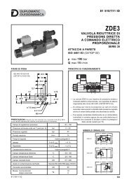
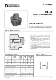
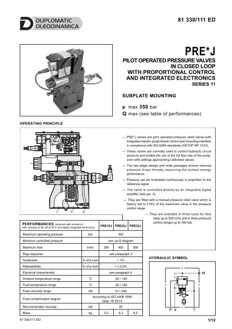
81 330/111 EDPRE*JPILOT OPERATED PRESSURE VALVESIN CLOSED LOOPWITH PROPORTIONAL CONTROLAND INTEGRATED ELECTRONICSSERIES 11SUBPLATE MOUNTINGp max 350 barQ max (see table of performances)OPERATING PRINCIPLE— PRE*J valves are pilot operated pressure relief valves withintegrated electric proportional control and mounting interfacein compliance with ISO 6264 standards (CETOP RP 121H).— These valves are normally used to control hydraulic circuitpressure and enable the use of the full flow rate of the pump,even with settings approaching calibrated values.— The two-stage design and wide passages ensure reducedpressure drops thereby improving the system energyperformance.— Pressure can be modulated continuously in proportion to thereference signal.— The valve is controlled directly by an integrated digitalamplifier (see par. 4).T P XPERFORMANCES (obtained with mineral oilwith viscosity of 36 cSt at 50°C and digital integrated electronics)— They are fitted with a manual pressure relief valve which isfactory set to ≥15% of the maximum value in the pressurecontrol range.— They are available in three sizes for flowrates up to 500 l/min and in three pressurecontrol ranges up to 350 bar.PRE10J PRE25J PRE32JMaximum operating pressure bar 350Minimum controlled pressuresee ∆p-Q diagramMaximum flow l/min 200 400 500Step response see paragraph 3Hysteresis % of p nom < 1%Repeatability % of p nom < ± 0,5%Electrical characteristic see paragraph 4Ambient temperature range °C -20 / +50Fluid temperature range °C -20 / +80Fluid viscosity range cSt 10 ÷ 400Fluid contamination degreeAccording to ISO 4406:1999class 18/16/13Recommended viscosity cSt 25Mass kg 5,5 6,3 8,5HYDRAULIC SYMBOLP XTM81 330/111 ED 1/12
PRE*JSERIES 111 - IDENTIFICATION CODEP R E J - /11 - K11 /Pilot operatedpressure reliefvalveElectric proportional controlSize: 10 = ISO 6264-06 (CETOP R06)25 = ISO 6264-08 (CETOP R08)32 = ISO 6264-10 (CETOP R10)Integrated electronics for pressure controlPressure control range:140 = up to 140 bar 350 = up to 350 bar210 = up to 210 barB = standard versionC = with CAN connectionMain connector 6 pin + PEReference signal:E0 = voltage 0 / +10VE1 = current 4 / 20mASeals:N = NBR seals for mineral oil (standard)V = FPM seals for special fluidsSeries No. (the overall and mounting dimensionsremain unchanged from 10 to 19)2 - CHARACTERISTIC CURVES (measured with viscosity of 36 cSt at 50°C)PRESSURE CONTROL p=f (I)p[bar]150 140p[bar]350350120902802102106014030700 1 2 3 4 5 6 7 8 9 100 1 2 3 4 5 6 7 8 9 10Rif [V]Rif [V]PRESSURE CONTROL p=f (Q)PRESSURE DROPS Dp = f(Q)p [bar]400PRE10JPRE25JPRE32JPRE*J-350p [bar]10PRE10JPRE25JPRE32J3008200PRE*J-2106100PRE*J-1404200100200 300400500Q [l/min]00 100 200 300400500Q [l/min]81 330/111 ED 2/12
PRE*JSERIES 113 - STEP RESPONSE (obtained with mineral oil with viscosity of 36 cSt at 50°C and with digital integrated electronics)p[bar]250200full scale 210 barfull scale 140 bar15010050020 40 60 80 0 2040t [ms]NOTE: Response times are obtained by using PRE25J valves with a full scale of 140 and 210 bar.4 - ELECTRICAL CHARACTERISTICS4.1 - Digital integrated electronicsThe proportional valve is controlled by a digital amplifier (driver), which incorporates a microprocessor that controls, via software, all the valvefunctions, such as:- continuous converting (0,5ms) of the voltage reference signal (E0) or of the current reference signal (E1) in a digital value- generation of up and down ramps (see NOTE)- gains limit (see NOTE)- compensation of the dead band- linearization of the characteristic curve- regulation of the current to the solenoid- dynamic regulation of PWM frequency- protection of the solenoid outputs against possible short circuitsNOTE: these parameters can be set through the connection to the CAN connector, by means of a personal computer and relevant software(see par. 5.3).The digital driver enables the valve to reach better performances compared to the analogic version, such as:- reduced hysteresis and improved repeatability- reduced response times- linearization of the characteristic curve which is optimised in factory for each valve- complete interchangeability in case of valve replacement- possibility to set, via software, the functional parameters- possibility to interface a CAN-Open network- possibility to perform a diagnostic program by means of the CAN connection- high immunity to electromagnetic troubles81 330/111 ED 3/12
PRE*JSERIES 114.2 - Functional block diagramABCDEFGPWMMINIMUMRAMP GAIN PRESSURE LINEARIZATION AMPLIFIERVIUP-DOWN3 4215C1 Valve with proportional solenoid 4 Main connector2 Electronics envelope 5 Pressure transducer3 Digital card4.3 - Electrical characteristicsNOMINAL VOLTAGE V DC 24 (from 19 to 35 VDC, ripple max 3 Vpp)ABSORBED POWER W 50MAXIMUM CURRENT A 1,88DUTY CYCLE 100%VOLTAGE SIGNAL (E0) V DC 0 ÷ 10 (Impedance Ri > 50KΩ)CURRENT SIGNAL (E1) mA 4 ÷ 20 (Impedance Ri = 500 Ω)ALARMSOverload and electronics overheatingCOMMUNICATION Interface of the optoisolated industrial Field-bus type CAN-Bus ISO 11898MAIN CONNECTOR 7 - pin MIL-C-5015-G (DIN 43563)CAN-BUS CONNECTOR M12-IEC 60947-5-2ELECTROMAGNETIC COMPATIBILITY (EMC)emissions CEI EN 61000-6-4immunity CEI EN 61000-4-2PROTECTION AGAINST ATMOSPHERIC AGENTSAccording to 2004/108/CE standardsIP67 (CEI EN 60529 standards)81 330/111 ED 4/12
PRE*JSERIES 115 - OPERATING MODALITIESThe digital driver of PRE*J valve may be used with different functions and operating modalities, depending on the requested performances.5.1 - Standard version with voltage reference signal (E0)This is the most common version; it makes the valve completely interchangeable with the traditional proportional valves with analog typeintegrated electronics. The valve has only to be connected as indicated below.This version doesn’t allow the setting of the valve parameters, for example the ramps must be performed in the PLC program, as well as thereference signal limit.Connection scheme (B version - E0)Pin Values Function NOTESA 24 VDC Voltage From 19 to 35 VDC (ripple max 3 Vpp)(see NOTE 2)B 0 V Power supply (zero) 0 VC ---- Not used ----D 0 ÷ 10 V Input rated command Impedance R i > 50 KΩE 0 V Input rated command ----F 0 ÷ 10 V Pressure test point 0 ÷ 100% nominal pressure (see NOTE1)PE GND Protective ground ----NOTE: If only one input signal is present, the pin B (0V power supply) and the pin E (0V reference signal) must be connected through a jumperand both connected to GND, electric panel side.5.2 - Standard version with current reference signal (E1)This version has characteristics which are similar to the previous one, with the difference that in this case the reference signal is supplied in current 4 -20 mA. With the 4 mA signal the valve is at zero value, while with 20 mA signal the valve is at the maximum setting value.Connection scheme (B version - E1)Pin Values Function NOTEA 24 VDC Voltage From 19 to 35 VDC (ripple max 3 Vpp)(see NOTE 2)B 0 V Power supply (zero) 0 VC ---- Not used ----D 4 ÷ 20 mA Input signal Impedance R i = 500 ΩE 0 V Zero reference ----F 0 ÷ 10 V Pressure test point 0 ÷ 100% nominal pressure (see NOTE 1)PE GND Protective ground ----NOTE for the wiring: connections must be made via the 7-pin plug mounted on the amplifier. Recommended cable sizes are 0,75 mm 2 forcables up to 20m and 1,00 mm 2 for cables up to 40m, for power supply. The signal cables must be 0,50 mm 2 . A suitable cable would have 7cores, a separate screen for the signal wires and an overall screen.NOTE 1: read the test point pin F in relation to pin B (0V).NOTE 2: Envisage an external fuse on pin A (24V DC) to shield the card. Fuse specifications: 5A/50V fast type.81 330/111 ED 5/12
PRE*JSERIES 115.3 - Version with parameters set by means of CAN connector (version C)This version allow to set some parameters of the valve connecting a PC to the CANconnector.To do this, you have to order the interface device for USB port CANPC-USB/20 (code3898101002), complete of the configuration software, a communication cable (length3 mt) and a hardware converter needed to connect the valve to the USB port. Thesoftware is Microsoft XP © compliant.The parameters that can be set are described below:PRESSUREPRESSIONEp fondo p full scala scale 100%Nominal pressureThe “nominal pressure” parameter sets the desired nominal pressure in bar, which themaximum reference value should be corresponding to (10 V or 20 mA).Default value = 100% of full scaleRange: from 100% to 50% of full scalePWM FrequencySets the PWM frequency, which is the pulsating frequency of the control current. ThePWM decrease improves the valve accuracy, decreasing the regulation stability.The PWM increase improves the regulation stability, causing a higher hysteresis.Default value = 300 HzRange 50 ÷ 500 Hzp nomPRESSUREPRESSIONE100%CONTROLCOMANDORampsIncrease time of Ramp R1: Sets the current increase time for a variation from 0 to 100%of the input reference.Decrease time of Ramp R2: Sets the current decrease time for a variation from 0 to100% of the input reference.Min time = 0,001 sec.Max time = 40,000 sec.Default time = 0,001 sec.DiagnosticsProvides several information parameters, such as:· The electronic driver status (Working or Broken)· The active regulation· Input reference· Current valuep maxR1UPDOWNR2TEMPO TIME81 330/111 ED 6/12
PRE*JSERIES 115.4 - Version with CAN-Bus interfaceThis version allows the valve piloting through the industrial field busCAN-Open, according to ISO 11898 standards.The CAN connector must be connected (see scheme) as a slavenode of the CAN-Open bus, while the main connector is wired onlyfor the power supply (pin A and B + earth).DIGITAL DRIVEμCMICROCONTROLLERACTIVENODEThe most important characteristics of a CAN - Open connectionare:- Parameter storage also in PLC- Parameters setting in real-time (PDO communication)- On-line valve diagnostics- Easy wiring with the serial connection- Communication program according to international standardsCAN-TRANSCEIVERCAN_CONTROLLERRxTxFor detailed information on the CAN-Open communicationsoftware, see cat. 89 800.CAN_HCAN_GNDCAN_LCAN_VCAN connector connection schemePin Values Functions120BUS_LINE1 CAN_SHLD Monitor2 CAN +24VDC BUS + 24 VDC (max 30 mA)3 CAN 0 DC BUS 0 VDC4 CAN_H BUS line (high signal)5 CAN_L BUS line (low signal)NOTE: insert a 120 Ω resistance on pin 4 and pin 5 of the CAN connector when the valve is the closure knot of the CAN network.6 - INSTALLATIONWe recommend to install the PRE*J valve either in horizontalposition, or vertical position with the solenoid downward. If the valveis installed in vertical position and with the solenoid upward, youmust consider possible variations of the minimum controlledpressure, if compared to what is indicated in paragraph 2.Ensure that there is no air in the hydraulic circuit. In particularapplications, it can be necessary to vent the air entrapped in thesolenoid tube, by using the appropriate drain screw in the solenoidtube. Ensure that the solenoid tube is always filled with oil (see par.8 - 9 - 10). At the end of the operation, make sure of havingcorrectly replaced the drain screw.Connect the valve T port directly to the tank. Add any backpressurevalue detected in the T line to the controlled pressure value.Maximum admissible backpressure in the T line, under operationalconditions, is 2 bar.7 - HYDRAULIC FLUIDSUse mineral oil-based hydraulic fluids HL or HM type, according toISO 6743-4.For these fluids, use NBR seals (code N). For fluids HFDR type(phosphate esters) use FPM seals (code V). For the use of otherkinds of fluid such as HFA, HFB, HFC, please consult our technicaldepartment. Using fluids at temperatures higher than 80 °C causesa faster degradation of the fluid and of the seals characteristics.The fluid must be preserved in its physical and chemicalcharacteristics.Surface finishingValves are fixed by means of screws or tie rods on a flat surfacewith planarity and roughness equal to or better than those indicatedin the relative symbols. If minimum values are not observed, fluidcan easily leak between the valve and support surface.81 330/111 ED 7/12
PRE*JSERIES 118 - OVERALL AND MOUNTING DIMENSIONS PRE10J567922042603226ø680117928622.153.847.561131380225853.826.9X P TXPTGø14.7 (max)ø4.8 ø7.5 M12Mounting interface: ISO 6264-06-09-*-97(CETOP 4.4.2-2-R06-350)Fastening bolts: N. 4 bolts M12x40Torque: 69 NmNOTE: at the first start up, or after a long period of no use, it isnecessary to vent the air through the breather (2) placed at the end ofthe solenoid tube.123456789dimensions in mmMounting surface with sealing rings:2 OR type 123 - 90 shore (17.86 x 2.62)1 OR type 109 - 90 shore (9.13 x 2.62)Breather (male hexagonal spanner 4)Pressure relief valve (factory set)Factory sealing setting (we recommendnot unscrewing the nut)Main connectionElectrical connector 7 pin DIN 43563 -IP67 PG11 EX7S/L/10 code 3890000003(to be ordered separately)CAN-Bus connection (only for version C)Electrical connector 5 pin M12 - IP67 PG7EC5S/M12L/10 code 3491001001only for version C(to be ordered separately)Cable with connectors for pressurefeedback81 330/111 ED 8/12
PRE*JSERIES 119 - OVERALL AND MOUNTING DIMENSIONS PRE25JMounting interface: ISO 6264-08-13-*-97(CETOP 4.4.2-2-R08-350)Fastening bolts: N. 4 bolts M16x50Torque: 170 NmNOTE: at the first start up, or after a long period of no use, itis necessary to vent the air through the breather (2) placedat the end of the solenoid tube.123456789dimensions in mmMounting surface with sealing rings:2 OR type 3118 - 90 shore (29.82 x 2.62)1 OR type 109 - 90 shore (9.13x 2.62)Breather (male hexagonal spanner 4)Pressure relief valve (factory set)Factory sealing setting (we recommendnot unscrewing the nut)Main connectionElectrical connector 7 pin DIN 43563 -IP67 PG11 EX7S/L/10 code 3890000003(to be ordered separately)CAN-Bus connection (only for version C)Electrical connector 5 pin M12 - IP67 PG7EC5S/M12L/10 code 3491001001only for version C(to be ordered separately)Cable with connectors for pressurefeedback81 330/111 ED 9/12
PRE*JSERIES 1110- OVERALL AND MOUNTING DIMENSIONS PRE32JMounting interface: ISO 6264-10-17-*-97(CETOP 4.4.2-2-R10-350)12dimensions in mmMounting surface with sealing rings:2 OR type 4137 - 90 shore (34.52 x 3.53)1 OR type 109 - 90 shore (9.13 x 2.62)Breather (male hexagonal spanner 2)Fastening bolts: N. 4 bolts M18x60Torque: 235 NmNOTE: at the first start up, or after a long period of no use, it isnecessary to vent the air through the breather (2) placed at the end ofthe solenoid tube.3456Pressure relief valve (factory set)Factory sealing setting (we recommendnot unscrewing the nut)Main connectionElectrical connector 7 pin DIN 43563 -IP67 PG11 EX7S/L/10 code 3890000003(to be ordered separately)7 CAN-Bus connection (only for version C)8 Electrical connector 5 pin M12 - IP67 PG7EC5S/M12L/10 code 3491001001only for version C(to be ordered separately)9Cable with connectors for pressurefeedback81 330/111 ED 10/12
PRE*JSERIES 1111 - SUBPLATES (see catalogue 51 000)PRE10 PRE25 PRE32Type PMRQ3-AI4G rear ports PMRQ5-AI5G rear ports PMRQ7-AI7G rear portsP, T port dimensions 1/2” BSP 1” BSP 1” ¼ BSPX port dimensions 1/4” BSP 1/4” BSP 1/4” BSP81 330/111 ED 11/12
PRE*JSERIES 11DUPLOMATIC OLEODINAMICA S.p.A.20015 PARABIAGO (MI) • Via M. Re Depaolini 24Tel. +39 0331.895.111Fax +39 0331.895.339www.duplomatic.com • e-mail: sales.exp@duplomatic.com81 330/111 ED REPRODUCTION IS FORBIDDEN. THE COMPANY RESERVES THE RIGHT TO APPLY ANY MODIFICATIONS.12/12