Thermal dissipation force modeling with preliminary results ... - ZARM
Thermal dissipation force modeling with preliminary results ... - ZARM
Thermal dissipation force modeling with preliminary results ... - ZARM

You also want an ePaper? Increase the reach of your titles
YUMPU automatically turns print PDFs into web optimized ePapers that Google loves.
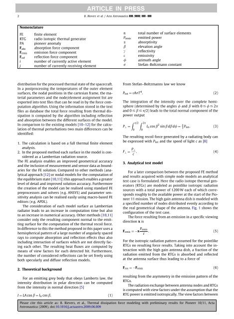
ARTICLE IN PRESS2 B. Rievers et al. / Acta Astronautica ( ) –NomenclatureFE finite elementRTG radio isotopic thermal generatorPA pioneer anomalyF abs absorption <strong>force</strong> componentF emis emission <strong>force</strong> componentF ref reflection <strong>force</strong> componenti number of currently active elementj number of currently receiving elementnP emisαβγεσtotal number of surface elementsemitted powerabsorptivityelevation anglereflectivityemissivityazimuth angleStefan–Boltzmann constantdistribution for the processed thermal state of the spacecraft.In a postprocessing the temperatures of the outer elementsurfaces, the nodal positions in the cartesian frame, the materialparameters and the node/element assignment list areexported into text files that can be read in by the <strong>force</strong> computationalgorithm. Using the information stored in the textfiles as database the total <strong>force</strong> resulting from thermal <strong>dissipation</strong>is computed by the algorithm including reflectionand absorption between the different surfaces of the model.In comparison to the existing models [10–12] for the calculationof thermal perturbations two main differences can beidentified:1. The calculation is based on a full thermal finite elementanalysis.2. In the proposed method each surface in the model is consideredas a Lambertian radiation source.The FE analysis enables an improved geometrical accuracyand the inclusion of measurement and sensor data as boundariesfor the FE solution. Compared to other methods (analyticalapproach [12] or nodal models for the computation ofthe equilibrium state [10,11]) this approach enables a greaterlevel of detail and improved solution accuracy. Furthermorethe creation of the model can be realised using standard FEpreprocessors and solvers (e.g. ANSYS) and parameter sensitivityanalysis can be realised easily using macro-based FEeditors (e.g. APDL).The consideration of each model surface as Lambertianradiator leads to an increase in computation time but alsoto an increase in numerical accuracy. Other methods [10,11]consider only the resulting component normal to the emittingsurface for the computation of the thermal recoil <strong>force</strong>.In difference to this the method proposed in this paper uses ahemispherical pattern of a large number of angularly spacedrays to compute absorption and reflection effects thus alsoincluding interaction of surfaces which are not directly facingeach other. The resulting heat fluxes are computed bymeans of view factors for each detected hit. Furthermore,the number of considered reflections can be set freely usingboth specularly and diffuse reflection models.2. Theoretical backgroundFor an emitting grey body that obeys Lamberts law, theintensity distribution in polar direction can be computedfrom the intensity in normal direction [5]I = LA cos β = I n cos β. (1)From Stefan–Boltzmanns law we knowP tot = εAσT 4 . (2)The integration of the intensity over the complete hemisphere(determined by the angles and β <strong>with</strong> 0 2πand 0 β π/2) leads to the total normal component of thepower output∫ π/2 ∫ 2πP ⊥ = I n cos β 2 sin β dβ d = 2 3 P tot. (3)0 0The resulting recoil <strong>force</strong> generated by a radiating body canbe expressed <strong>with</strong> P tot and the speed of light c as [8]F ⊥ = P ⊥c . (4)3. Analytical test modelFor a later comparison between the proposed FE methodand <strong>results</strong> acquired <strong>with</strong> simple node models an analyticaltest case is formulated. Here the radio isotope thermal generators(RTGs) are modeled as pointlike isotropic radiationsources <strong>with</strong> a total power of 1200 W each of which correspondsroughly to the available power at the start of the Pioneer11 mission. The high gain antenna dish is modeled <strong>with</strong>a specified number of nodes distributed evenly according tothe real geometrical shape of the antenna. Fig. 1 shows theconfiguration of the test case.The <strong>force</strong> resulting from an emission in a specific viewingdirection x isF emis =−x P emis. (5)cFor the isotropic radiation pattern assumed for the pointlikeRTGs no resulting <strong>force</strong> <strong>results</strong>. Taking into account the interaction<strong>with</strong> the high gain antenna dish, a fraction of theradiation emitted from the RTGs is absorbed and reflectedat the antenna surface thus leading to a <strong>force</strong> ofF res =−F emis (6)resulting from the asymmetry in the emission pattern of theRTGs.The radiation exchange between antenna nodes and RTGsis computed <strong>with</strong> view factors under the assumption that theRTG power is emitted isotropically. The view factors betweenPlease cite this article as: B. Rievers, et al., <strong>Thermal</strong> <strong>dissipation</strong> <strong>force</strong> <strong>modeling</strong> <strong>with</strong> <strong>preliminary</strong> <strong>results</strong> for Pioneer 10/11, ActaAstronautica (2009), doi:10.1016/j.actaastro.2009.06.009