Thermal dissipation force modeling with preliminary results ... - ZARM
Thermal dissipation force modeling with preliminary results ... - ZARM
Thermal dissipation force modeling with preliminary results ... - ZARM

You also want an ePaper? Increase the reach of your titles
YUMPU automatically turns print PDFs into web optimized ePapers that Google loves.
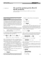
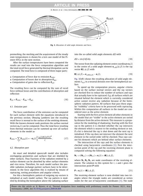
ARTICLE IN PRESSB. Rievers et al. / Acta Astronautica ( ) – 5Fig. 3. Allocation of solid angle elements and <strong>force</strong>.premeshing, the meshing and the acquirement of the steadystate temperatures is shown for a test case model of the PioneerRTGs in the next section.After the surface temperatures have been computed the<strong>results</strong> are read into the <strong>force</strong> computation algorithm andthe total recoil <strong>force</strong> generated by thermal <strong>dissipation</strong> can becomputed. The total <strong>force</strong> is composed of three major parts:• Computation of <strong>force</strong> due to emission F emis .• Computation of losses due to absorption F abs .• Computation of gains due to reflection F ref .The resulting <strong>force</strong> can be computed by the sum of recoil<strong>force</strong> <strong>with</strong>out losses and the contributions of absorption andreflectionF tot = F emis − F abs + F ref . (16)4.1. Emission partThe <strong>force</strong> contribution of the emission can be computedfor each surface element <strong>with</strong> the equations introduced inthe previous section. Obeying Lamberts law the resultingrecoil <strong>force</strong> is normal to the surface of the emitting element.With the known element node positions the surface normalvectors e n (i) can be computed. Thus the total <strong>force</strong> resultingfrom thermal emission can be summed up over all surfaceelements in the model asF emis = ∑ i4.2. Absorption partF emis (i) =−e n (i) 2 ε A (i)A(i)σT(i) 4. (17)3 cAn exact and detailed spacecraft model also includesoverlapping geometries and surfaces that are shielded byother surfaces. Thus fractions of the radiation emitted by asurface element can be absorbed by other surface elementsand vice-versa. Therefore, for each model surface the possibleradiation exchange partner surfaces have to be determined.In the <strong>force</strong> algorithm this is realised by means ofraytracing, sorting procedures and angular criteria.For this a hemispheric pattern of outgoing ray-vectors isinitialised at each model surface. The ray pattern is modeledby dividing the hemisphere above the radiating surfaceinto the so-called solid angle elements dΩ <strong>with</strong>dΩ = sin β dβ d. (18)The vector from the radiating element centre coordinate e c (i)to the centre of a solid angle element e c,dΩ (, β) is the rayvector R(i, , β) <strong>with</strong>R(i, , β) = e c,dΩ(,β) − e c (i). (19)Fig. 3(left) shows the resulting allocation of solid angle elementsS ,β in a tesseral division over the hemispherical surface.To speed up the computation process, angular criteriabased on the surface normal vectors and the ray vectorsare checked first to reduce the number of surfaces and raysthat actually have to be raytraced. E.g. all surfaces which aresituated behind the element which is currently consideredactive cannot receive any radiation because of the hemisphericradiation pattern. All surfaces that pass these angular“visibility” criteria have to be processed <strong>with</strong> raytracing.Within this computation all surfaces in the model are consideredonce as the active element.Starting <strong>with</strong> the first active element all other elements inthe model that are “visible” to the active element are sortedby distance from the active element. This measure is a preparationfor the <strong>modeling</strong> of shadowing. Starting <strong>with</strong> the firstray in the pattern it is checked whether the ray intersectsthe element which is nearest to the sending element or not.If a hit is detected the ray is shut down and the next ray isinitialised. If the ray does not intersect the element the nextelement in the sorted order will be checked. Thus rays cannothit elements which are behind other surface elements.The intersection of the rays and the surface elements ischecked using barycentric coordinates [1]. First the intersectionpoint of the ray and the receiving element plane iscomputed solving the following equation:N 1 + r(N 2,1 ) + s(N 3,1 ) = e c (i) + tR(i, , β), (20)where N 1 , N 2 , N 3 are node coordinates of the receiving element.The solution to this system for r, s and t gives theintersection point P <strong>with</strong>P = e c (i) + tR(i, , β). (21)The receiving element surface is now divided into two triangleswhere the triangle nodes are considered as vertexnodes for the use of barycentric coordinates [1]. The nodePlease cite this article as: B. Rievers, et al., <strong>Thermal</strong> <strong>dissipation</strong> <strong>force</strong> <strong>modeling</strong> <strong>with</strong> <strong>preliminary</strong> <strong>results</strong> for Pioneer 10/11, ActaAstronautica (2009), doi:10.1016/j.actaastro.2009.06.009