INSTALLATION AND OPERATION MANUAL
INSTALLATION AND OPERATION MANUAL
INSTALLATION AND OPERATION MANUAL

You also want an ePaper? Increase the reach of your titles
YUMPU automatically turns print PDFs into web optimized ePapers that Google loves.
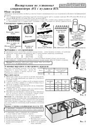
ELECTRICAL CONNECTIONS1) Connection to the electricity main• Feeder line;The feeder line of the machine must follow a well defined route without interruptions. Run the line through the precut hole at thebottom of the right panel on the machine. It is advisable to use a cable gland, to secure the line to the machine structure. Nowroute the line inside the compressor compartment until it reaches the hole in the bottom of the electric panel. Here again, makesure you use an adequately sized cable clamp, use a high temperature cable or sheath, not place the cable or sheath onthe compressors.Connect the conductors straight to the input terminals of the main circuit-breaker of the machine.• Powering system;The power cables of the feeder line of the machine must come from a symmetric threephase voltage system complete with neutralconductor and separate protection conductor.V= 400V ± 10%f= 50 Hz• Protection on supply side;An automatic switch must be installed on the supply side of the side in order to protect against any overcurrents and indirect contactsthat could occur when the machine is operating.It is advisable to install an automatic current limiter switch in order to limit the effective short-circuit current in the connecting pointof the machine. This allows a protection device with a lower breaking capacity than that required in the connection point to besized like the main circuit-breaker of the machine.The line and switch must be coordinated in compliance with the current laws governing electrical safety matters, regarding thetype of installation and environmental conditions in which the machine must operate.• Protection conductor (ground wire);The protection conductor from the feeder line must be connected straight to the ground screw identified by code "PE", whichensures the equipotential connection of all metal grounding points and structural parts of the machine.• Neutral conductor:The neutral conductor in the feeder line must be connected to the neutral conductor identified by the letter "N" corresponding tothe fourth pole of the main panel circuit-breaker.2) Electric panel• Protection degree:The electric panel casing is made of galvanised sheet metal and has an IP54 protection degree in corre spondence to the door,which can be directly accessed from outside. The other parts of the casing guarantee a protection degree that is at least equivalentto IP22, as established by the current laws in force: this has been achieved since the panel has further protection againstthe penetration of solid foreign bodies and atmospheric agents thanks to the machine structure in which it is housed.• Starting and stopping function:The red handle on the panel door directly acts on the main circuit-breaker. The handle also acts as a door lock since it ensuresthat the machine is only powered when the door is shut. The stopping function carried out by the main circuit-breaker is classifiedas type "0" since the machine is stopped by immediately cutting off the power supply.• Emergency function:The handle also acts as an emergency stop since it can be directly accessed from outside and is also evident owing to its redcolour.3) Reference standards• The provisions established by the following Directives have been complied with to ensure the safety of the electrical productsplaced on the European Union market:- Low Voltage Directive 2006/95 EEC which also includes the following harmonized standards:CEI EN 60335-1 and 60335-2-40.Classification:CEI EN 60204-1. Safety of machinery. Electrical equipment of machines. Part 1:General rules.- Directive 2004/108/EEC concerning "Electromagnetic compatibility".46