412CF SUBJECT: ENGINE FIRE EXTINGUISHER BOTTLE STEM ...
412CF SUBJECT: ENGINE FIRE EXTINGUISHER BOTTLE STEM ...
412CF SUBJECT: ENGINE FIRE EXTINGUISHER BOTTLE STEM ...

Create successful ePaper yourself
Turn your PDF publications into a flip-book with our unique Google optimized e-Paper software.
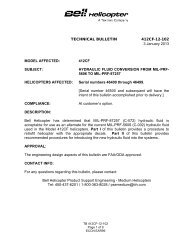
ALERT SERVICE BULLETIN<strong>412CF</strong>-12-4918 December 2012MODEL AFFECTED:<strong>SUBJECT</strong>:<strong>412CF</strong><strong>ENGINE</strong> <strong>FIRE</strong> <strong>EXTINGUISHER</strong> <strong>BOTTLE</strong> <strong>STEM</strong>INSPECTIONHELICOPTERS AFFECTED: Serial numbers 46400 through 46499.[Serial number 46500 and subsequent will have theintent of this bulletin accomplished prior to delivery.]COMPLIANCE: Part I: Stem fittings are to be inspected before May 1 st ,2013.DESCRIPTION:Part II or Part III: Discharge tube rework orreplacement shall be completed before December 1 st ,2013.Part IV: Tubes modified per Part II of this bulletin areto be inspected every 600 hour / 12 month or until PartIII is accomplished.Bell Helicopter has been made aware of engine fire extinguisher bottle stem fitting (P/N13034, 31840000 or 31840000) failures due to corrosion. This has occurred on PacificScientific, HTL / Kin-Tech Division fire extinguisher bottles. This bulletin provides visualinspection guidance for the fire extinguisher bottle stem fittings on fire extinguishercontainers P/N 209-062-908-105. The corrosion is the result of wash fluid entering thefire extinguisher agent delivery tube holes, which can flow backwards to the bottlefittings. Rework of the dispersant tube to add a drain hole is provided within this bulletin.Discharge tubes must be reworked or replaced to meet the intent of this bulletin.Applicability of this bulletin to any spare part shall be determined prior to its installationon an affected helicopter.APPROVAL:The engineering design aspects of this bulletin are FAA/ODA approved.ASB <strong>412CF</strong>-12-49Page 1 of 12ECCN EAR99
CONTACT INFO:For any question regarding this bulletin, please contact:MANPOWER:Bell Helicopter Product Support EngineeringMedium HelicoptersTel: 1-800-363-8028 / psemedium@bh.comApproximately 4 man-hours are required to complete this bulletin. This estimate isbased on hands-on time, and may vary with personnel and facilities available.WARRANTY:There is no warranty credit applicable for parts or labor associated with this bulletin.MATERIAL:Required Material:The following material is required for the accomplishment of this bulletin and may beobtained through your Bell Helicopter Textron Supply Center.Part Number Nomenclature Qty212-060-921-101212-060-921-102AN735C16NAS1802-3-7NAS1149C0316RMS21043-3*Required for Part III only**Required for Part II onlyConsumable Material:None required.SPECIAL TOOLS:None required.Tube assemblyTube assemblyLoop ClampBoltWasherNut1*1*2**2**2**2**ASB <strong>412CF</strong>-12-49Page 2 of 12ECCN EAR99
4. Using a safety mirror, inspect fire bottle discharge nozzle stem (ref. Figure 3) forcorrosion, by viewing into the discharge outlet as indicated in Pacific Scientific, HTL /Kin-Tech Division Bulletin SB-30402901-<strong>STEM</strong> (ref. www.pacificscientific.com).CAUTIONCorrosion damage that has reduced any one stem leg by anestimated 50 percent must be treated with extreme cautionto prevent inadvertent discharge.CAUTIONDo not rotate outlet, cartridge or housing nut when corrosionis evident.5. When corrosion is detected, refer to Pacific Scientific, HTL / Kin-Tech DivisionBulletin SB-30402901-<strong>STEM</strong>.6. If corrosion damage is estimated to be 50 percent or more on any one of the stemlegs it is necessary to discharge the fire bottle before returning it to an authorizedservice center for nozzle replacement as indicated in Pacific Scientific, HTL / Kin-Tech Division Bulletin SB-30402901-<strong>STEM</strong>.7. Fire extinguisher bottles requiring replacement due to corrosion shall be removedand installed as per C-12-146-000/MF-001 Maintenance Manual.-NOTE-When accomplishing Part II or Part III of this bulletinconcurrently with Part I, tube installation is not required.8. Install tubes 1, 2, 3 and 4 as shown in Figures 1 and 2 for completion of Part I of theaccomplishment instructions.9. Remove extinguisher bottle squib jumper wires (shorting device) and connectelectrical wires to fire extinguisher bottle as per C-12-146-000/MF-001 MaintenanceManual.10. Make an entry in the helicopter logbook and historical service records indicatingcompliance with Part I of this bulletin.ASB <strong>412CF</strong>-12-49Page 4 of 12ECCN EAR99
Part III. Discharge Tube Replacement-NOTE-When accomplishing Part III of this bulletin, Part II and PartIV are not required.1. Prepare helicopter for maintenance.WARNINGMake sure that no power is applied to helicopter electricalsystems and helicopter is properly grounded whileperforming maintenance on fire extinguishing system.2. Disconnect tubes 1, 2, 3 and 4 (ref. Figures 1 and 2).3. Disconnect existing discharge tubes P/N 212-060-921-001/-001FM and -002/002FMand then loosen nut AN924-16 on aft tee fittings to provide sufficient space toremove discharge tube (ref. Figure 4).4. Install replacement tubes P/N 212-060-921-101 and -102 containing drain holes.5. Install tubes 1, 2, 3 and 4 and tighten fitting (ref. Figures 1 and 2).6. Make an entry in the helicopter logbook and historical service records indicatingcompliance with Part III of this Alert Service Bulletin.Part IV. Modified Discharge Tube Inspection-NOTE-Part IV Inspection not required when Part III Discharge TubeReplacement has been accomplished.ASB <strong>412CF</strong>-12-49Page 6 of 12ECCN EAR99
1. Visually inspect the loop clamp P/N AN735C16 installed on modified dischargetubes P/N 212-060-921-001FM and -002FM every 600 hour / 12 month for conditionand security or until Part III of this bulletin is accomplished.2. Make an entry in the helicopter logbook and historical service records indicatingcompliance with Part IV of this bulletin.ASB <strong>412CF</strong>-12-49Page 7 of 12ECCN EAR99
1. Tube assembly 212-060-915-0012. Tube assembly 212-060-936-001Figure 1 - View Center line Looking RightASB <strong>412CF</strong>-12-49Page 8 of 12ECCN EAR99
3. Tube assembly 212-060-919-0014. Tube assembly 212-060-930-001Figure 2 - View Center Line Looking LeftASB <strong>412CF</strong>-12-49Page 9 of 12ECCN EAR99
Figure 3 - View Looking Into the Discharge Outlet at StemASB <strong>412CF</strong>-12-49Page 10 of 12ECCN EAR99
Figure 4 - Discharge Tubes 212-060-921-002 R/H (shown),P/N 212-060-921-001 (opposite)ASB <strong>412CF</strong>-12-49Page 11 of 12ECCN EAR99
Figure 5 - Tube ModificationsASB <strong>412CF</strong>-12-49Page 12 of 12ECCN EAR99
HTL/KIN-TECH DIVISIONSERVICE BULLETINTO: OPERATORS WHO HAVE PACIFIC SCIENTIFIC UNIT 30402901-X (BELL PARTNUMBER 209-062-908-001 and 105) INSTALLED ON BELL 212/412HELICOPTERS<strong>SUBJECT</strong>: POSSIBLE SUDDEN RELEASE OF OUTLET ASSEMBLY1. INTRODUCTIONPacific Scientific has been advised by Bell Helicopter of the possibility of the referenced unit havinguncontrolled sudden release of the outlet assembly due to stem corrosion. If washer water or itsresidue remains on the discharge nozzle stem, corrosion and possible failure could result.2. SCOPEThis Service Bulletin applies only to Pacific Scientific unit part number 30402901-X installed onBell 212/412 helicopters.3. REFERENCEAll available safety guides.4. COMPLIANCEMandatory5. INSTRUCTIONSA. With unit installed on airframe: (Unit is under pressure: acknowledge and use all safetyprocedures and equipment.)1. Disconnect outlet hoses from unit.2. With strong light and safety mirror, look inside unit outlet. Do not look directly into nozzle untilservicability has been established.a. If no corrosion is visible, re-attach hose and document findings.(see below for sample of unit with no corrosion)SB 30402901-<strong>STEM</strong>February 10, 2012Pacific Scientific Company d/b/a Pacific Scientific Aviation Services11700 Northwest 102 nd Road, Suite 6, Miami FL 33178, USAPacific Scientific CompanyTel: +1 (305) 477 4711Fax: +1 (305) 477 9799www.pacificscientific.comwww.meggitt.com
5. INSTRUCTIONS (continued)b. If any corrosion is present, send unit for service.(Due to nature of discrepancy do not directly look into outlet)(Do not rotate outlet, cartridge, or housing nut)(see below for samples of corrosion and corrosion residue)c. If 50% or more of the stem leg is intact, (see photo) unit may be shipped forservice with unit charged. If 50% or less of any leg is intact request kit anddischarge unit.Discharge InformationB. Obtain discharge kit from Pacific Scientific Aviation Services (see CONTACTINFORMATION(Unit is under pressure, acknowledge and use all safety procedures and equipment.)(Due to nature of discrepancy do not directly look into outlet)(Do not rotate outlet, cartridge, or housing nut)C. Remove unit from helicopter, secure unit in vice using attach lugs.Install NAS1612-4 supplied in kit on unit fill fitting. (see below)SB 30402901-<strong>STEM</strong>February 10, 20125. INSTRUCTIONS (continued)
D. Attach discharge tool 59000060 to unit, hand tight only, open valve (round-shaped, black knob) ontool. (see below)(If unit outlets and tool present interference do not rotate outlets, remove andreplace valve from tool.)E. Attach hose to tool and receiving tank. (see below)Tank is under vacuum, see gauge on receiving bottle, do not open valve untilready for discharge.If mistake occurs attach tank to vacuum source only if tank is empty.F. Holding 59000060 tool upright twist open handle on discharge tool. (tool on bottom, bottleon top) You should hear flow of contents, tool and bottle will get cold(see below)SB 30402901-<strong>STEM</strong>February 10, 2012
5. INSTRUCTIONS (continued)G. Open gate valve slowly on receiving tank, ensure tool is up-right(tool on bottom bottle on top)(You will hear agent rush into tank, transfer will take seconds)H.. Check gauge, wait till reading stabilizes.I. Close tool valve handle and close gate valve on receiving tank.J. Remove hose from tool.Slight residual agent may release from hose.K. Tool valve handle can be opened to release remaining nitrogen gas. Once gas is released,close tool valve handle.(release of nitrogen gas will be colorless and harmless)L. When unit is totally empty retract “T” handle on tool to retract fill fitting plunger.M. Repeat steps C through L for other unit if required. Do not use discharge kit to dischargemore than 2 units.N. Repack tools and enclose bottles.O. Send to Pacific Scientific (see CONTACT INFORMATION)SB 30402901-<strong>STEM</strong>February 10, 2012