
You also want an ePaper? Increase the reach of your titles
YUMPU automatically turns print PDFs into web optimized ePapers that Google loves.
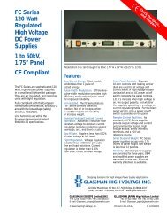
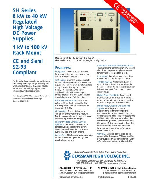
<strong>SH</strong> <strong>Series</strong>8 kW to 40 kWRegulated<strong>High</strong> <strong>Voltage</strong>DC PowerSupplies1 kV to 100 kVRack MountCE and SemiS2-93CompliantThe <strong>SH</strong> family of power supplies are sophisticated,8 kW through 40 kW, high voltage power supplieswith low ripple and noise. They are air insulatedfast response units with tight regulation andextremely low arc discharge currents.Fully Compliant With The European harmonizedEMI directive and with the low voltagedirective, 73/23/EEC.Models from 0 to 1 kV through 0 to 100 kV.8kW models are 17.5”H x 24.0” D. Weight is only 110 lbs.Features:Arc Quench. The HV output is inhibitedfor a short period after each load arc toquickly extinguish the arc.Arc Sensing. Internal circuitry constantlysenses and integrates arcs that occur overa given time. In the event a system or loadarcing problem develops and exceedsfactory-set parameters, the powersupply will cycle off in an attemptto clear the fault and then automaticallyrestart after a preset “off dwell time”.Pulse-Width Modulation. Off-the-linepulse-width modulation provides highefficiency and a reduced parts count forimproved reliability.Air Insulated. The <strong>SH</strong> <strong>Series</strong> features“air” as the primary dielectric medium.No oil or encapsulation is used to impedeserviceability or increase weight.Constant <strong>Voltage</strong>/Constant CurrentOperation. Automatic crossover fromconstant-voltage to constant-currentregulation provides protection againstoverloads, arcs, and short circuits.Current Trip. This feature may be substitutedfor constant-current operation by a rearpanel selector switch.Check the specs…and compareRedundant Thermal Overload Protection.Thermostats and tachometer fan RPM sensingshut down the power supply due to overtemperature or reduced fan speeds.Low Ripple. Typically, ripple is less than0.025% rms of rated voltage at full load.Tight Regulation. <strong>Voltage</strong> regulation istypically better than 0.01% for allowableline and load variations. Current regulationis better than 0.1% from short circuit torated voltage.<strong>High</strong>er Power Capability. Power supplymodules can be paralleled up to 40 kWoutput power utilizing one master controlmodule and up to four slave modules.Differentially Coupled Analog ControlSignals. All voltage and currentprogramming and monitoring signalsare coupled to the user interface by truedifferential amplifiers. This provides for theability to return the program and monitorcommons to ground or system common atthe source. This arrangement isolates thereturn wires and eliminates errors dueto unwanted return currents flowing inthese connections.Warranty. Standard power supplies arewarranted for three years; OEM and modifiedpower supplies are warranted for one year.A formal warranty statement is available.Designing Solutions for <strong>High</strong> <strong>Voltage</strong> Power Supply ApplicationsGLASSMAN HIGH VOLTAGE INC.124 West Main Street, PO Box 317, <strong>High</strong> Bridge, NJ 08829-0317(908) 638-3800 • Fax (908) 638-3700 • www.glassmanhv.comGLASSMAN EUROPE Limited (UK) GLASSMAN JAPAN <strong>High</strong> <strong>Voltage</strong> Limited+44 1256 883007 FAX +44 1256 883017 +81 45 902 9988 FAX +81 45 902 2268E-mail: <strong>Glassman</strong>_europe@glassmanhv.com E-mail: <strong>Glassman</strong>_japan@glassmanhv.com©<strong>Glassman</strong> <strong>High</strong> <strong>Voltage</strong>, <strong>Inc</strong>. Printed in the U.S.A. C 9/8/2003
SpecificationsSpecifications for 8 kW Power Supplies(Specifications apply from 5% to 100% ofrated voltage. Operation is guaranteeddown to zero with a slight degradation ofperformance.)(For 16 kW power supplies, unless otherwiseindicated, the performance specificationlimits could be increased by a factor of upto 30%. For power supplies over 16 kWconsult the factory.)Input: 187-228 V rms, three-phase,48-63 Hz, 11,500 VA maximum at full load(less than 35 A per phase). Inrush currentis less than 45 A with a nominal decay timeconstant of 60 ms. Four 10-32 studs forAC line connection with a safety cover andstrain relief are provided. For systems16 kW and greater, a separate AC inputconnection is required for each additionalslave chassis.Mains service must be protected withfuses or circuit breakers with a maximumrating of 125 A and a minimum interruptingcapacity of 50,000 A.Efficiency: Typically 85% at full load.Output: Continuous, stable adjustmentfrom 0 to rated voltage/current by meansof panel-mounted 10-turn potentiometers(0.05% resolution), or external 0 to +10 Vsignals. Repeatability better than 0.1%of setting.<strong>Voltage</strong> programming accuracy: 0.5% ofsetting + 0.2% of rated output.Resolution is a function of the programmingmethod used.<strong>Voltage</strong> and current external programmingare differentially coupled with a maximumcommon mode voltage of ±3 VDC.<strong>Voltage</strong> Regulation: Better than ±0.005%for specified line variations and 0.01% +10 mV/A for no load to full load variations.Current Regulation: From short circuit torated voltage at any load condition:1 kV to 6 kV: Better than 0.5%.8 kV to 100 kV: Better than 0.2%<strong>Voltage</strong> Monitor: 0 to +10 V equivalent to0 to rated voltage. Accuracy, 0.5% of reading+ 0.2% of rating. Output impedanceis 10 kΩ differentially coupled.Current Monitor: 0 to +10 V equivalentto 0 to rated current. Accuracy:1 kV to 6 kV: 1.5% of reading plus0.5% of rated output.8 kV to 100 kV: 1% of reading plus0.2% of rated output.Output impedance is 10 kΩ differentiallycoupled.Ripple: Better than 0.025% of ratedvoltage +1 V RMS at full load.Stored Energy: See Models chart.Stability: 0.01% per hour after 1/2 hourwarm-up, 0.05% per 8 hours.<strong>Voltage</strong> Rise Time Constant: 200 ms for8 kV to 100 kV models and 50 ms for 1 kV to6 kV models typical, using either HV enableor remote programming control.<strong>Voltage</strong> Decay time constant: Decay timeconstant is a function of the applied load.The decay time constant will be equal tothe rise time constant with a minimumload of 5% of rated maximum.Temperature Coefficient: 0.01%/° C.Ambient Temperature: -20 to +40° C,operating; -40 to +85° C, storage.Polarity: Available with either Positive,Negative, or Reversible polarity with respectto chassis ground.Protection: Automatic current regulationprotects against all overloads, includingarcs and short circuits. Thermal switchesand rpm sensing fans protect againstthermal overload. Circuit breaker, fuses,surge-limiting resistors, and low energycomponents provide ultimate protection.Arc Quench. Optional on models 1 kVthrough 6 kV; standard on models 8 kVthrough 100 kV. An arc quench featureprovides sensing of each load arc andquickly inhibits the HV output forapproximately 20 ms after each arc.Arc Sensing. Optional on models 1 kVthrough 6 kV; standard on models 8 kVthrough 100 kV. Internal circuitry senses thenumber of arcs caused by external loaddischarges. If the rate of consecutive arcsexceeds approximately one arc per secondfor five arcs, the supply will turn off forapproximately five seconds to allowclearance of the fault. After this period, thesupply will return automatically to theprogrammed output voltage value with thevoltage rise time constant indicated. If theload fault still exists, the above cycle willbe repeated.Current Limit: In current limit mode thepower supply will regulate the load currentat the programmed current level withautomatic crossover between voltageand current regulating modes.Current Trip: A switch located on the rearof the control panel assembly allows theselection of current limit or current tripoperation. When the switch is set to currenttrip mode, the HV output will disable andlatch off when the load current reaches theprogrammed current level. Reset is accomplishedby either cycling the AC power,toggling the HV enable signal, or by pushingthe HV off/reset and then the HV on switches.Front Panel Elements. The front panelcontains all local control functions andremote/local selector switches. Thesecontrol functions are: AC power on/offcircuit breaker and indicator light, separate10-turn controls with locking vernier dialsused to set voltage and current levels, highvoltage on switch, and high voltage off/resetswitch. LED's indicate: when high voltageis on, output polarity, interlock, fault status,and whether the supply is operating in avoltage or current regulating mode. Outputlevels are indicated by voltage and currentdigital meters. Remote/local switches areprovided for voltage and current programmingand HV on/off functions.Slave Front Panel Elements. (Whenapplicable). AC power breaker/switchand indicator. Bias, tracking (overvoltage),and thermal overload/low fan speedindicators. Slave current and voltageservice test points.Remote Control Interface. All standard<strong>SH</strong> family power supplies provide a user'sremote interface. The signals provided are:Inputs:Safety interlock, output voltage andcurrent program signals, high voltageenable and connections for remote HVon and off pushbuttons.Outputs:Output voltage and current monitorsignals, HV enable status, I/Vregulation mode status, fault status,and a +10 V reference source.Signal common and ground referenceterminals are also provided.Toggle switches on the rear of the controlchassis select either current limit orcurrent trip operation and local orremote HV enable.External Interlock: Open = off,closed = on. Normally latching except for"NC" option supplies where it is non-latchingThe interlock indicator LED is lit whenthe interlock is open.HV Enable:Remote Mode: 0 - 1.5 V = OFF,2.5 - 15 V = ON.Local Mode: The HV output ispermanently enabled.HV Enable, Fault and I/V Regulation Status:Each are a set of form “C”relay contacts.Accessories: Detachable, 8 foot, shieldedhigh voltage coaxial cable provided. Models16 kW and above are provided with anadditional HV cable per slave module.A 25 pin D-subminiature connector forcustomer interface is provided. All chassisinterconnection cables are provided.
OptionsSymbol DescriptionZR Zero start interlock. <strong>Voltage</strong> control, local or remote, must be at zero before HV will enable.SS Slow start ramp. Specify standard times of 5, 10, 15, 20, or 30 seconds ± 20% .5VC 0-5 V voltage and current program/monitor.NC Blank front panel. Panel contains AC power breaker/switch and indicator, HV ON, HV OFF, interlock and faultindicators, and output current and voltage service test points.ARC For 1 to 6 kV models. Arc quench and arc sensing are provided as described in specifications for8 to 100 kV models.Please consult factory for special requirements.8 kW ModelsPositive Negative Reversible Output Output Stored OutputPolarity Polarity Polarity <strong>Voltage</strong> Current Energy Cable(J)<strong>SH</strong>1R8.0 0 – 1kV 0 – 8.0A 8 RG-8UReversible PolarityOnly<strong>SH</strong>1.5R5.3 0 – 1.5kV 0 – 5.3A 7.8 RG-8U<strong>SH</strong>2R4.0 0 – 2kV 0 – 4.0A 7.5 RG-8U<strong>SH</strong>3R2.7 0 – 3kV 0 – 2.7A 8 RG-8U<strong>SH</strong>5R1.6 0 – 5kV 0 – 1.6A 7 RG-8U<strong>SH</strong>6R1.3 0 – 6kV 0 – 1.3A 8 RG-8U<strong>SH</strong>8P1.0 <strong>SH</strong>8N1.0 <strong>SH</strong>8R1.0 0 – 8kV 0 –1000mA 10 RG-8U<strong>SH</strong>10P800 <strong>SH</strong>10N800 <strong>SH</strong>10R800 0 – 10kV 0 – 800mA 12 RG-8U<strong>SH</strong>12P670 <strong>SH</strong>12N670 <strong>SH</strong>12R670 0 – 12kV 0 – 670mA 12 RG-8U<strong>SH</strong>15P530 <strong>SH</strong>15N530 <strong>SH</strong>15R530 0 – 15kV 0 – 530mA 10 RG-8U<strong>SH</strong>20P400 <strong>SH</strong>20N400 <strong>SH</strong>20R400 0 – 20kV 0 – 400mA 18 RG-8U<strong>SH</strong>25P320 <strong>SH</strong>25N320 <strong>SH</strong>25R320 0 – 25kV 0 – 320mA 13 RG-8U<strong>SH</strong>30P270 <strong>SH</strong>30N270 <strong>SH</strong>30R270 0 – 30kV 0 – 270mA 18 RG-8U<strong>SH</strong>40P200 <strong>SH</strong>40N200 <strong>SH</strong>40R200 0 – 40kV 0 – 200mA 16 RG-8U<strong>SH</strong>50P160 <strong>SH</strong>50N160 <strong>SH</strong>50R160 0 – 50kV 0 – 160mA 20 RG-8U<strong>SH</strong>60P130 <strong>SH</strong>60N130 <strong>SH</strong>60R130 0 – 60kV 0 – 130mA 24 RG-8U<strong>SH</strong>70P110 <strong>SH</strong>70N110 <strong>SH</strong>70R110 0 – 70kV 0 – 110mA 28 DS2121<strong>SH</strong>80P100 <strong>SH</strong>80N100 <strong>SH</strong>80R100 0 – 80kV 0 – 100mA 32 DS2121<strong>SH</strong>100P80 <strong>SH</strong>100N80 <strong>SH</strong>100R80 0 – 100kV 0 – 80mA 40 DS212116 kW ModelsPositive Negative Reversible Output Output Stored OutputPolarity Polarity Polarity <strong>Voltage</strong> Current Energy Cable(J)<strong>SH</strong>1R16.0 0 – 1kV 0 – 16.0A 16 2X RG-8UReversible PolarityOnly<strong>SH</strong>1.5R10.6 0 – 1.5kV 0 – 10.6A 15.6 2X RG-8U<strong>SH</strong>2R8.0 0 – 2kV 0 – 8.0A 15 2X RG-8U<strong>SH</strong>3R5.4 0 – 3kV 0 – 5.4A 16 2X RG-8U<strong>SH</strong>5R3.2 0 – 5kV 0 – 3.2A 14 2X RG-8U<strong>SH</strong>6R2.6 0 – 6kV 0 – 2.6A 16 2X RG-8U<strong>SH</strong>8P2.0 <strong>SH</strong>8N2.0 <strong>SH</strong>8R2.0 0 – 8kV 0 – 2.0A 20 2X RG-8U<strong>SH</strong>10P1.6 <strong>SH</strong>10N1.6 <strong>SH</strong>10R1.6 0 – 10kV 0 – 1.6A 24 2X RG-8U<strong>SH</strong>12P1.3 <strong>SH</strong>12N1.3 <strong>SH</strong>12R1.3 0 – 12kV 0 – 1.3A 24 2X RG-8U<strong>SH</strong>15P1.06 <strong>SH</strong>15N1.06 <strong>SH</strong>15R1.06 0 – 15kV 0 – 1060mA 20 2X RG-8U<strong>SH</strong>20P800 <strong>SH</strong>20N800 <strong>SH</strong>20R800 0 – 20kV 0 – 800mA 36 2X RG-8U<strong>SH</strong>25P640 <strong>SH</strong>25N640 <strong>SH</strong>25R640 0 – 25kV 0 – 640mA 26 2X RG-8U<strong>SH</strong>30P540 <strong>SH</strong>30N540 <strong>SH</strong>30R540 0 – 30kV 0 – 540mA 36 2X RG-8U<strong>SH</strong>40P400 <strong>SH</strong>40N400 <strong>SH</strong>40R400 0 – 40kV 0 – 400mA 32 2X RG-8U<strong>SH</strong>50P320 <strong>SH</strong>50N320 <strong>SH</strong>50R320 0 – 50kV 0 – 320mA 40 2X RG-8U<strong>SH</strong>60P260 <strong>SH</strong>60N260 <strong>SH</strong>60R260 0 – 60kV 0 – 260mA 48 2X RG-8U<strong>SH</strong>70P220 <strong>SH</strong>70N220 <strong>SH</strong>70R220 0 – 70kV 0 – 220mA 56 2X DS2121<strong>SH</strong>80P200 <strong>SH</strong>80N200 <strong>SH</strong>80R200 0 – 80kV 0 – 200mA 64 2X DS2121<strong>SH</strong>100P160 <strong>SH</strong>100N160 <strong>SH</strong>100R160 0 – 100kV 0 – 160mA 80 2X DS2121For Models Greater Than 16 kW, Please Consult Factory.
8 kW Models16 kW ModelsDesigning Solutions for <strong>High</strong> <strong>Voltage</strong> Power Supply ApplicationsGLASSMAN HIGH VOLTAGE INC.124 West Main Street, PO Box 317, <strong>High</strong> Bridge, NJ 08829-0317(908) 638-3800 • Fax (908) 638-3700 • www.glassmanhv.com