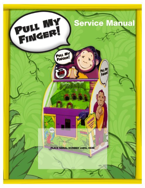
Pull My Finger
Pull My Finger
Pull My Finger

You also want an ePaper? Increase the reach of your titles
YUMPU automatically turns print PDFs into web optimized ePapers that Google loves.
FACTORY CONTACT INFORMATIONOur Vision:We aspire to be thebest in the world atdeveloping andmanufacturing coinoperated games forour customers.BAY TEK GAMES INC.Pulaski Industrial Park1077 East Glenbrook DrivePulaski, WI 54162 U.S.A.www.baytekgames.comJOIN SERVICE FIRST NETWORK!This free service is intended to keep you up todate on the latest game information, earlynotification of parts specials, pertinent technicalbulletins, updates on retro fit parts, softwareupgrades, & much more. Log on to:www.baytekgames.com/parts& then click on the Service First icon.8 AM - 5 PM C.S.T. MON - FRISALESP: 920.822.3951F: 920.822.8936sales@baytekgames.comPARTSP: 920.822.3951 x 1101F: 920.822.1496parts@baytekgames.comSERVICE:P: 920.822.3951 X 1102F: 920.822.1496service@baytekgames.comAll games proudly manufactured at our factory in Pulaski, Wisconsin U.S.A.2
TABLE OF CONTENTSFACTORY CONTACT INFORMATION 2TABLE OF CONTENTS 3INTRODUCTION 4INSPECTION 4SPECIFICATIONS 5SAFETY PRECAUTIONS 5HOW TO PLAY 6QUICK SET-UP GUIDE 7-9DETAILED OPERATIONS/ MAIN MENU 10DIAGNOSTICS 11CREDITS/BALLS PER PLAY SETTINGS 12TICKET PATTERN SETTINGS 13-14BIG BONUS SETTINGS 15VOLUME SETTINGS 16GAME STATISTICS 17-18HOW TO: INSTALL BILL ACCEPTOR 19CIRCUIT BOARD WIRING 20CABLE DIAGRAMS 21-25TROUBLESHOOTING GUIDE 26-30POWER SUPPLY DIAGNOSTICS 31BILL ACCEPTOR DIAGNOSTICS 32PARTS LIST 33PART IDENTIFICATION 34-35DECAL IDENTIFICATION 36WIRING DIAGRAMS 37-40MAINTENANCE LOG 41TECHNICAL SUPPORT 42WARRANTY 433
WELCOME TO: <strong>Pull</strong> <strong>My</strong> <strong>Finger</strong>Congratulations on your <strong>Pull</strong> <strong>My</strong> <strong>Finger</strong> purchase!You already know this product delivers much more than an action-filledgame with big profits. <strong>Pull</strong> <strong>My</strong> <strong>Finger</strong> is, in simple terms, the epitome ofgoofy fun! It replicates the kind of fun we had as kids, and has the innateability to sweep a family with laughter in a matter of seconds!Please take a moment to read through this manual and be sure to contactour factory if you have any questions, or would like some more information.<strong>Pull</strong> <strong>My</strong> <strong>Finger</strong> has built in playfield diagnostics, automatic data tracking(viewable on the marquee displays), dual ticket trays, and a sweet choreographypackage that keeps people playing…and laughing…and playing…and, well you get the point!Enjoy!Your business is important to us and we hope you enjoy this game as muchas we do!Your Friends at Bay Tek GamesGAME INSPECTIONInspect the game for any damaged, loose, or missing parts. If damage is found,please contact your freight carrier first. Then, contact Bay Tek GamesService Department at 920.822.3951 or e-mail them atservice@baytekgames.com for further assistance.4
SPECIFICATIONSWEIGHTWEIGHT675 lbs.POWER REQUIREMENTSSHIP WEIGHT755 lbs.INPUT VOLTAGE RANGE 110 to 120 VAC or 220 to 240 VACDIMENSIONSWIDTH 49”INPUT FREQUENCY RANGE 50 HZ to 60 HZDEPTH 32 1/4”HEIGHT 91”OPERATING TEMPERATURE80 - 100 Degrees Fahrenheit26.7 - 37.8 Degrees CelsiusMAX START UPCURRENT1.6 AMPS @ 115 VAC0.8 AMPS @ 230 VACOPERATINGCURRENT1.3 AMPS @ 115 VAC.65 AMPS @ 230 VACSAFETY PRECAUTIONSDANGERDO NOT perform repairs or maintenance on this game with the power ON. Unplugthe unit from the wall outlet or shut off the power at the power strip located insidethe game cabinet.WARNINGUse of flammable substances can cause severe burns or serious injury.Always use NON-FLAMMABLE solvents for cleaning.DO NOT use gasoline, kerosene, or thinners.CAUTIONLifting heavy objects can cause back, neck, or other injuries. Be sureadequate lifting and moving devices are available when unloading,unpacking, and moving this game.ATTENTIONBe sure the electrical power matches the game requirements. See the serial numberdecal located on the back of the game cabinet. Always plug game into agrounded circuit. If the supply cord is damaged, it must be replaced by a specialcord or assembly available from the manufacturer or itsservice agent.5
HOW TO PLAY: <strong>Pull</strong> <strong>My</strong> <strong>Finger</strong><strong>Pull</strong> <strong>My</strong> <strong>Finger</strong> is a bright and colorful ticketredemption game that encourages players to pull the monkey's finger,which shoots a ball into the playfield where six targets are located.The targets display alternating ticket values for an added challenge. Iftiming and accuracy are on point, players can win the big bonus. Thisselectable bonus ranges from 25 tickets all the way up to a whopping1000 bonus tickets! (Factory default is 250)If the ball does not go straight into a target, automatic flippers havebeen installed on the playfield to keep the ball bouncing until it islaunched into a target.The large, bright and colorful cabinet draws players to this simpleticket redemption game, while the charismatic monkey keeps kids ofall ages highly entertained time and time again!Standard features include: dual ticket dispensers, adjustable bonuspatterns, built in diagnostics, and performance tracking software.6
QUICK SET-UP GUIDETools needed:1/2” socket & ratchet5/32” Allen wrench or drill with #2 square bit7/16” socket & ratchetLocate the package of keys (taped tothe front of the game). It should includefive sets of either B10 or 644keys, and one set of 631 keys.Open the cashbox door with the 631key, and remove the hardwarepacket and power cord.Remove the lower back door with twoB10 or 644 keys, and take out thehand assembly and guard.Also remove the bag of balls (16total), and place them in the ballchute7
QUICK SET-UP GUIDE, cont.Attach the guard to the side of thecabinet with the three 2” carriagebolts, three flat washers, and three5/16” locknuts.Make sure the washers go on the insideof the cabinet, between thewood and the lock nuts.Attach the hand assembly with fourblack self-tapping square bit screwsand split washers.8
QUICK SET-UP GUIDE, cont.Slide the marquee onto the cabinetfrom the front, making sure the powercable goes safely down the openingwithout getting pinched.Secure the marquee from inside thetop back door, inserting 1 1/2” hexbolts with split and flat washers intothe holes in either side.Plug in the marquee power anddisplay cables.Plug the cable from the cashbox intothe back of the cabinet and connect itto a power source.Push the cabinet to its final locationand lock the casters.Load the ticket trays with tickets.Power the game on by switching thepower strip to “ON”.Congratulations! You’re Ready To Go!9
DETAILED OPERATIONSMAIN MENU1. Access the main menu by pressing the“MENU BUTTON” inside the front door ofthe cabinet and holding down for 4 seconds.2. Scroll through the menu options shown onthe 4-digit display by pressing the “MENUBUTTON” repeatedly.3. Press the “MENU SELECT” button to enterand scroll through sub-menus (described indetail below).SUB-MENU DESCRIPTIONSn1n2n3n4n5n6n7n8-11GAME DIAGNOSTICS:Used to trouble-shoot sensors and ball flippersCREDITS PER PLAY:Allows operators to choose the number of credits requiredto playBALLS PER PLAY:Allows operators to choose how many balls are played percreditTICKET PATTERN:Allows operators to choose the desired ticket payout pertargetBIG BONUS SETTING:Allows operators to choose the desired ticket payout(shown on the 4-digit display) when the Big Bonus is hitGAME VOLUME:Adjusts the volume of the game during play (after a coinhas been inserted)ATTRACT MODE VOLUME:Adjusts the volume of the game while it is not in useSTATISTICS:Gives detailed information on game performance. Thesewill be described in more depth on page 14.10
N1– GAME DIAGNOSTICSThe game diagnostics mode will allow you to test the following components tomake sure they are working correctly:Remove the window from the cabinetBALL LAUNCHER SENSOR:• With the ball launcher empty, make sure the 4-digit display reads “0”• Place the ball into the launcher• If the sensors are working correctly, a “1” should appear on the display in placeof the “0”*if the display reads “1” while no ball is in the launcher, it is malfunctioning*TARGET SENSORS:• Place your hand inside each of the targetsindividually• The lights around the targets should flash ifthey are working correctly*If the lights come on without an object passing throughthe target, they are malfunctioning*BALL FLIPPERS:• Gently push down each flipper to make surethey react11
N2– CREDITS PER PLAYScroll through the n2 menu with the “menu select” button.Make your selection by pressing the “menu button” and scrollingthrough the remaining menus past n10 to exit the menu.Factory default settings are highlighted in yellow.CREDITSPER PLAYPRICEPER PLAY0 1 2 3 4 5 6 7 8FREE $.25 $.50 $.75 $1.00 $1.25 $1.50 $1.75 $2.00N3– BALLS PER PLAYScroll through the n2 menu with the “menu select” button.Make your selection by pressing the “menu button” and scrollingthrough the remaining menus past n10 to exit the menu.Factory default settings are highlighted in yellow.1 2 3 412
N4– TICKET PATTERNSScroll through the n3 menu with the “menu select” button.Make your selection by pressing the “menu button” and scrollingthrough the remaining menus past n10 to exit the menu.34562113
TARGET #N4– TICKET PATTERNS, cont.0121 5/S*2 5/S*3 204 305 406 100Factory default settings are highlighted in yellow.TARGET #TICKETS1 2/S*2 2/S*3 104 155 406 100TARGET #TICKETS1 1/S*2 1/S*3 54 105 256 50TICKETS3451 1/S*1 2/S*1 1/S*TARGET #2 1/S*3 54 105 15TICKETSTARGET #2 4/S*3 64 105 20TICKETSTARGET #2 1/S*3 34 45 5TICKETS6 256 506 15*S= SKILL TICKETS(changes with Big Bonus settings in n4 menu, see pg. 12)The SKILL SHOT values alternate with the regular pattern valueson targets 1 & 214
N6– GAME VOLUME CONTROLScroll through the n6 menu with the “menu select” button.Make your selection by pressing the “menu button” and scrollingthrough the remaining menus past n10 to exit the menu.Factory default settings are highlighted in yellow.0 1 2 3 4 5 6 7 8(OFF)This control is for the volume of the game while it is being played, orafter a coin has been inserted.A drum beat will play an example volume while scrolling through thevolume levels.N7– ATTRACT VOLUME CONTROLScroll through the n7 menu with the “menu select” button.Make your selection by pressing the “menu button” and scrollingthrough the remaining menus past n10 to exit the menu.Factory default settings are highlighted in yellow.0 1 2 3 4 5 6 7 8(OFF)This control is for the volume of the game while it is NOT beingplayed. This game plays fun, attracting sounds to lure customers toplay.A drum beat will play an example volume while scrolling through thevolume levels.16
N10– SKILL HITS COUNTERThis statistics mode will display a count of “skill shot” hits ontargets 1 & 2.A “skill hit” is when the ball goes through target 1 or 2 while the higheralternate value is displayed.• If these numbers are high, you may have a very skilled player, or “shark”,frequenting your facility. This may cause your game to pay out too manytickets. Because <strong>Pull</strong> <strong>My</strong> <strong>Finger</strong> is a skill-based game, this is a possibility.The total number of games played is shown on the 4-digit display.N11– STATISTICS CLEARWhile in n11 mode, hold down “menu select” for 3 secondsto clear the statistics in menus n8-n10.The statistics modes (n8-n10) will display “0” on all targets and 4-digitdisplay when viewed again after clearing.18
HOW TO: INSTALL BILL ACCEPTORTools Needed: 11/32” Nut Driver or socket wrench1.) Remove 4 nuts from bill acceptorplate and 2 from coin mech bolts.2.) Remove black bill acceptor plate.3.) Insert Bill Acceptor.4.) Install nuts on bill acceptorplate and coin mech.5.) Route cables as shown in picture.6.) Make sure Bill Acceptor is set to“Always Enabled” and test.19
הקטין.בהקשר זה יש לציין את פקודות המטה הארצי של המשטרה שלפיהן אין חובה לאפשרנוכחות הורים בחקירת קטין מעל גיל 14, וניתן שיקול דעת לשוטרים גם במקרה שלחובת נוכחות הורים. 36 אם כך הדבר בנוגע לחוקר משטרה, בהליך שעשוי לפגוע בזכויותהקטין – ושבו נדרשת נוכחות הורים לשם הגנה על הקטין, האם אי אפשר להסיק בדרךשל קל וחומר כי גם סניגור – שתפקידו לשמור על זכויות הקטין – יכול להפעיל שיקולדעת בנוגע לנוכחות ההורים? נראה שהדבר מחייב שינוי חקיקה, והבהרה לגבי זכויותהקטין בהליך הפלילי.נקודת המוצא של הכללים שניסחנו היא, כי על פי חובת הנאמנות ללקוח, מחויב גםסניגור של קטינים לפעול לפי רצון לקוחותיו, ובכלל זה רצונם בנוגע לשיתוף ההוריםבהליך.הקטין והוריוכלל 5חובת נאמנות לקטין:סניגור המייצג קטין בהליך הפלילי מייצג את הקטין בלבד ולא את הוריו. הסניגור יבהירזאת לקטין ולהוריו בתחילת המפגש עמם. הסניגור יחתור ליחסי אמון ושיתוף פעולה עםההורים ככל האפשר, וכל עוד הדבר עולה בקנה אחד עם רצונו של הקטין ועם ההגנההמשפטית עליו.36 פקודת המטה הארצי של משטרת ישראל – 14.01.05 עבודת המשטרה עם קטינים, סעיף 3)ג()1()ג(:"בחקירת קטינים עד גיל 14 חובה לאפשר נוכחות הורה או אפוטרופוס. בחקירת קטינים מעל גיל 14,אין חובה לאפשר נוכחות הורה או אפוטרופוס. סייגים לגבי הכללים החלים על נוכחות הורים, לגבי שתיהאוכלוסיות, מפורטים בהנחיית מח"ק/נוער." אלי שרון מביע הסתייגות מפקודה זו, בטענה כי לפי חוקהנוער וחוק הכשרות זכות ההורים להיות נוכחים בחקירה, ואין לאפשר שיקול דעת של שוטרים להוציאםמהחקירה. שרון, לעיל הערה 33, בעמ' 281-263.20
Coin Door and Bill Acceptor CableTo J6 (COIN)and J8 onMain BoardCoin Door Cable—AACE9109Coin Door HarnessAACBL4A-DOORCoin Switches(AASW9903)Wired NormalOpenTo Outlet StripAC VoltageTo Bill AcceptorBall Lift Sensor & Volume CableSpeaker/LED Cable AACE9100To SpeakerTo J19 (SPEAKERS)and J24 connector onmain board +-To Ball Lift SensorAACB1901Playfield bottom LED lightsAACE9119Ball Lift Sensor Cable AACE9110Menu Buttons Cable—AACE9107To J25 Connectoron Main BoardAAPB690Menu ButtonAAPB690Menu SelectButton21
Ball Lift Motor & Counters Cable—AACE9103To Ball Lift Motor—A5MO4010~16 OhmsTo J22 Connectoronmain board+-Top LED lights—AACE9101TicketCounterTicket and Game Counters—AACO1000GameCounterTicket Dispenser / Low Ticket Switches DisplayTo J21 Connectoron Main BoardTo I/O J12 on Aux BoardThese are signal lines for Jackpot Display BoardAACE9124Ticket Tray CableAACE1615To Ticket Dispenser - A5TD112 Volt PowerEnable SignalCom GroundNotch SignalAACE91082nd Ticket Dispenserhassame wiringpath.Game GroundLow Ticket SwitchWired Normally OpenA5SW2001/4” Spacer A5SENY02022
12 Volt Power Supply WiringPower SupplyA5PS1001Green LEDpower indicatorand voltageadjustment potPower SupplyPower CableAACE9105Power Supply12 Volt CableAACE9115To J18 Connectoron I/OAUX BoardTo J18“POWER IN”Connector onMain Board23
Ball Sensor Wiring DiagramAACE9116AACB9110AACB9110AACB9110AACB9110AACE9102AACE9102AACE9102AACE9112AACE9125AACE9125AACB9111AACB9111From J10 Connectoron Main Board—AACE9111AACE911324
Ball Sensor, Ball Release, Jackpot Display and Flipper WiringCom Cable to J16on Main BoardAACE9114Ball Release SolenoidAASO9100 (13 Ohms)Ball Flipper - All 3 arethe same - 4 OhmsAAFL9100AACE9123Sensor atPlungerAACE4407To Sensor at PlungerAACE9121Jackpot Display BoardAACB143725
TROUBLE SHOOTING GUIDETroubleshooting StrategyUse common sense and a systematic method of troubleshooting to determine the exact problem, probable cause andremedy. Use the process of elimination to find the faulty component. Always check for the simple and obvious causesfirst such as unplugged, loose or broken wires and bad sensors, bent, pinched, stuck or jammed components.Troubleshooting ChartProblem Probable Cause RemedyNo power to the game.No lights on at all.AC Light and Bill Acceptoron.But everything else off.(Power Supply not ON)Dollar Bill Acceptor notfunctioning.Game not coining up.Unplugged.Circuit breaker tripped.Power strip faulty.Faulty cable/power supply.Power supply unplugged.Power supply shutting downbecause of 12 V overload.Faulty power supply.Check for power to Bill Acceptor.Dirt or debris in acceptorslot.Pinched, broken, or disconnectedwiring.Bill acceptor problem.Ensure game makes “Dong”sound when coin switch istriggered.Game set to large amount ofcredits per game.26Check wall outlet.Reset power strip breaker switch or buildingcircuit breaker.Change plug position, replace if needed.See Power Supply diagnostic below.Insure unit is plugged into power strip.See power supply diagnostics to isolate badcomponent. A bad motor or 12 volt shortwould cause this.See Power Supply Diagnostic below.Acceptor should cycle stacker at gamepower up. If not, check cable connections.Refer to “How to Clean Bill Acceptor”Or clean with bill reader cleaning card.(A5CC9000)Check wiring from bill acceptorto Main Board. (AACE9109)Repair or replace wiring harness.Check J8 connector on MainBoard—Makesure wires are secure in connector.Refer to troubleshooting section of dollar billacceptor manual included with thisgame or the diagnostics label of theback of the unit.Check coin switches—both should be wirednormally open. Check wiring to main board.Cable AACBL4A-DOOR, AACE9109Jackpot display will show credits inserted.Enter N2 mode in menu to set credits pergame.
TROUBLE SHOOTING GUIDEProblem Probable Cause RemedyGame scoreswrong valuesGame does notscore target.Game is scoring too soon –before coin reaches sensor.Players think they won bonus.Back door removed or broken.Faulty target sensor.Disconnected, loose or brokenwires.Faulty I/O Aux Board.Faulty sensor – Align and clean sensors or replace sensor.(AACB9110 - Top row sensor)(AACB9111 - Bottom row sensor)“Skill Shot” values are constantly changing and are on aset timer. The value on the target at instant ball passessensor is what the player receives.The back door has ball guides that help divert the ball. Replaceback door. (AADO9100)Align and clean sensors or replace sensor.(AACB9110 - Top row sensor or AACB9111 - Bottom row sensor)Check connectors and clean phone jack sockets on I/OAux Board and main board. Check for continuity.Cable #’s : 9116, 9125, 9124Check connections and clean phone jack sockets on AuxBoard and main board.Game pays 5 more tickets than it should.One of the ticket dispensers is not seeing the notch signal.The dispenser will time out after 5 tickets.Opto Sensor on ticket dispenserdirty.Blow dust from sensor and cleanwith isopropyl alcohol.Tickets do notdispense orWrong amountdispensed.Tickets OwedDisplay is addingup correct.Faulty ticket dispenser.Notch on tickets cut too shallow.Replace with working dispenser toisolate the problem. (A5TD1)Flip tickets and load upside-downto have large cut notch toward optosensor.Check for thecorrect amountof tickets addingup on TicketsOwed DisplayTickets OwedDisplay is notadding correctlyFaulty cable. Disconnected, looseor broken wires.Faulty Main Board.Game is scoring too soon – beforecoin reaches Slot sensor board.Ensure “Skill Shot” values arechanging on display above sensor.The values are constantly changingand are on a set timer.27Check connectors from ticket dispensersto main board. Check forcontinuity.Check cables 1615, 9108Replace main board.Score sensor is faulty. Align andclean sensors or replace sensor.AACB9110 - Top row sensorAACB9111 - Bottom row sensorThe value on the target at instantball passes sensor is what theplayer receives.
TROUBLE SHOOTING GUIDEProblem Probable Cause RemedyNo SoundVolume set to zero in menu.Disconnected, loose or brokenwires.Faulty speaker.Enter N6 in menu for game volume.Enter N7 in menu for attract volume.Check connections and reseat J19 on mainboard. Cable # AACE9100Replace speaker. A5SP1050Targets not lighting upNote: Target lights arewired separate from targetsensors.Jackpot Display notlighting upJackpot Display says“Lo”Game looks fine, butnone of the functionswork.Targets are wired in series. If oneis faulty, all of the targets after itwill go dark.Check previous target and targetwhich is dark.Swap target boards to isolateproblem.Faulty target sensor.Phone Cable to Display is bent,pinched or unplugged.J12 connector on I/O Aux Boardto main board disconnected.Faulty Display Board.Both ticket trays are empty.Disconnected, loose or brokenwires.Faulty low ticket switches.Faulty Main Board.I/O Aux Board may be faulty,wires disconnected from mainboard, or not receiving 12 VDCpower.Refer to Ball Sensor Wiring Diagram. Cablegoes from Main Board to bottom sensors totop sensors.Check connections and clean phone jacksockets on targets and main board.Note: Top row sensors are different from bottomrow sensors.Replace sensor.AACB9110 - Top row sensorAACB9111 - Bottom row sensorCheck connections and clean phone jacksockets on display board and I/O Aux board.Replace cable if needed. AACE9123Check connections and reseat J12, and J21on main board. Cable # AACE9124Replace Display Board. AACB1437Refill trays with tickets.Check connections and reseat J21 on mainboard. Cable #’s 9124, 9108, 1615Switches wired normally open. Replaceswitches. A5SW200Replace main board. Part # AANEWGEN1Check I/O Aux Board for any disconnectedwires.Check 12 Volts DC to J18.Check J16 plug on I/O Aux Board to J21 onmain board.28
Displayshows Err 1TROUBLE SHOOTING GUIDEErr 1 means there is no ball in front of plunger after coin up.There can be multiple causes, including:Not enough balls in game. Ensure 16 balls in game.Playfield Kicker not working. Refer to Playfield Kicker not working below.Ball Load motor not working. Refer to Ball Load Motor not working below.Ball release solenoid not working. Refer to Ball Release Solenoid not working below.Ball load sensor not seen. Clean or replace sensor. AACB1901Problem Probable Cause RemedyPlayfield Flipper not working.One ball stuck in front of FlipperSwap inputs on I/O Aux board toverify flipper fault.Ball Load Motor does not work.Ball loader will load ball at coinup if no ball is at plunger, thencycle 15 seconds twice, then goto Err1. It will try again after 40seconds.No Balls on playfield.If no ball is preset at coin up, game willload one immediately and then tryagain after 15 seconds.Too many balls on playfieldSwitch not making contact onflipper assembly.Disconnected, loose or brokenwires.Flipper solenoid faulty.Problem may follow socket on I/OAux Board.Disconnected, loose or brokenwires.Faulty Motor.Faulty Main Board.Sensor at Plunger blocked orfaulty.Faulty Ball Load MotorI/O Aux Board is not communicating.Ball Lift Sensor faulty causingload motor to always turn.Ball Flipper switch faulty causinggame to keep loading ballsbecause it can not find them.Ball Flipper Solenoid faulty.Sensor at Plunger faulty.Inspect flipper assembly, replace ifneeded. AAFL9100Check connectors from flipper to I/OAux Board.Replace flipper. (4 Ohms) AAFL9100Replace I/O Aux Board. AACB9107Check connectors from Motor toMain Board.Replace Motor. A5MO4010Replace Main Board. AANEWGEN1Clean sensor, check for togglemovement. Replace sensor.(AACE4407)Refer to Ball Load Motor does notwork above.I/O Aux Board may be faulty, wiresdisconnected from main board, ornot receiving 12 VDC power.Clean sensor. Check wiring. Replacesensor. (AACB1901)Check continuity through switch.Swap Flipper to isolate problem.Replace flipper (AAFL9100)Swap Flipper to isolate problem.Replace flipper- 4 Ohms (AAFL9100)Sensor does not see ball in position,so game continues to load balls.Replace sensor. (AACE4407)29
TROUBLE SHOOTING GUIDEProblem Probable Cause RemedyBall release solenoid notworking.Too many balls on playfieldDisconnected, loose or brokenwires.Faulty solenoid.I/O Aux Board connection.Faulty I/O Aux Board.Check connectors from Ball ReleaseSolenoid to I/O Aux BoardCheck for 13 Ohms across coil.Replace if needed. AASO9100Ensure I/O Aux Board has 12 Voltpower on J18. Check J16 Com cable.Replace I/O Aux Board.AACB9107More information on the I/O Aux BoardThe I/O Aux Board has logic on board which monitors sensor inputs and provides 12 volt pulses to coils to operate.It provides this information back to main board via the J16 Communication cable. (AACE9114)It is important that this cable is securely connected to theJ16 socket on the main board. (Blue colored socket)Power game down when disconnecting and reconnecting this cable. Wait 10 seconds before power up.J16—#9114 Communicationcable to J16 on main board.J18—#9115 12 Volt DC Power InJ12—#9124 Display communicationfrom J21 on main boardJ23—#9123 Ticket Jackpot Display CableThe I/O Aux Board also acts as a connector board forJackpot Display Board.Signals come in on J12, and go to display on J23.Jackpot Display will not work if either cable is faulty.30
POWER SUPPLY DIAGNOSTICSUse the following procedure to check the Power Supply for Gen 5games.Start by removing the backdoor to gain access to the Power Supply.It is mounted directly to the left of the PCB.Look for the small green LED light on the Power Supply circuit board.If the light is out there is a short somewhere. If the light dims, there isan overload in one of the circuits such as a bad motor.Turn power OFF. Disconnect all 12 voltoutput wires only. Turn power ON.Green LED Lightcomes ON.Green LED Lightremains OFF.Replace PowerSupply.(A5PS1001)Turn power OFF. Unplug all outputs from the large PCB. Reconnectthe 12 volt output wires to the Power Supply. Turn powerON.Green LED Lightcomes ON.Green LED Lightremains OFF.Short in PCB -Replace.Turn power OFF. Reconnectthe outputs atthe PCB one at a time.Wait 60 seconds betweentests to turnpower ON.Green LED Lightcomes ON.Green LED Lightremains OFF.Green LED Lightdims.That cable is OK.That cable or related componentis shorted out. SeeJumper Cable Pin-Outs tosee which component mightbe at fault.A related component suchas a solenoid is causing anoverload. See Jumper CablePin-Outs in manual tosee which component mightbe at fault.31
BILL ACCEPTOR DIAGNOSTICSNote: There are many different models and brands of Bill Acceptors that are used on redemptiongames. Your Bill Acceptor may differ from the unit shown.First determine if Bill Acceptor has power:Turn game ON—The bill acceptor should make noise as stacker cycles andgreen lights on outside bezel should flash.If NO power:Due to the different models and brands of Bill Acceptors that are used:Examine Bill Acceptor and determine if acceptor is 12 Volt DC or 110 VACUse meter to measure voltage at cable going into Bill Acceptor.If power is OK:Clean Bill Acceptor path to make sure there is nothing jamming unit.Enter DBA Diagnostics Mode -Important—Do not hold button down for more than 5 seconds or BillAcceptor will enter programming mode.If programming mode is entered by mistake—Unplug game and plug back in.To enter Diagnostic Mode, press and hold theDiagnostic Button on the back left corner of the DBA for1-3 seconds.The lights above the bill slot will flash the code.ERROR CODESCount the number of flashes on front bezel of Bill Acceptor andfollow chart for repair.FLASHINGCODEDESCRIPTIONCORRECTIVEACTIONLEDs off Power off Turn on powerLEDs onAcceptor is OK1 flash Bill path blockage Un-jam bill path2 flashes Stacker jam Un-jam stacker3 flashes Cassette is full of bills Empty the cassette4 flashes Cassette is removed Replace the cassette5 flashes Acceptor is defective Replace the acceptor6 flashes Acceptor not enabled See service manual10 flashes Configuration Mode Power down to exitRapid flashingduring operationStringing attempt detected;or sensors dirtyClean the sensors32
PARTS LISTPART # DESCRIPTIONA5BA9100 Ball, Purple, 8 Per GameA5BA9101 Ball, Yellow, 8 Per GameA5CB1499 Coin boxA5CO4203 Speaker coverA5FI9010 Inline FilterA5HU1200 HubA5LI0001 Fluorescent light, 120v 60hzA5LK2000 631 Lock with KeysA5LK5001 644 Lock with KeysA5LK6000 Back Door Lock with KeysA5LE9100 Large Leaf, 4 Per GameA5MO4010 MotorA5PL9097 Plate, (Replaces Bill Acceptor)A5PS1001 Power SupplyA5SP9103 Spring, Pin, 32 Per GameA5SP9104 Spring, Ball GuideA5SW200 SwitchA5TD1 Ticket DispenserA5VF9100 Vacuum Form, Purple MarqueeA5VF9101 Vacuum Form, Playfield Ball GuideA5ME9129 Metal, Target Sensor CoverA5DE9109 Decal, Marquee, Title BubbleA5DE9110 Decal, Marquee, FaceA5DE9111 Decal, Marquee, ArmA5DE9112 Decal, Marquee, BodyA5DE9114 Decal, Marquee, Right EarA5DE9115 Decal, Marquee, Bubble 1A5DE9116 Decal, Marquee, Bubble 2A5DE9117 Decal, Inside MarqueeA5DE9118 Decal, Playfield Cover, LeftA5DE9119 Decal, Playfield Cover, RightA5DE9120 Decal, Marquee, Left EarA5DE9124 Decal, Left Light CoverA5DE9125 Decal, Right Light CoverA5DE9126 Decal, Back Door CoverPART # DESCRIPTIONA5CA1002 Caster, WheelW5TM4006 T-Molding, 13/16" YellowAACO1000 CountersAALIHL110 Fluorescent Light Holder Assy.AACE8802 Outlet StripAACE9122 Ball Release Solenoid W/CableAAPB2700 Push Button Assy. (Menu Button)AACE8811 Speaker Assy W/CableAACB9101 Lights on Top of PlayfieldAACB9107 Goes to Menu ButtonAACB9124 Low Ticket to Aux BoardAACBL4A-DOOR Door CableAACE4319 Fluorescent Light CableAACE9100 Speaker to Playfield LightsAACE9103 Fl. Light to Motor to Ticket CountersAACE9104 Top Marquee Fluorescent Light WireAACE9105 Power Supply WireAACE9108 Main Board to Ticket TrayAACE9109 DBA to Coin DoorAACE9110 Slot Sensor to Auger to Fluorescent LightAACE9115 Power Supply to Main Board to Aux BoardAACE9117 Cable to Flipper Solenoid, 2 Per GameAACE9120 Cable to Flipper Solenoid, 1 Per GameAACE9121 Aux Board to Ball Sensor to #2 TargetAACE9125 Aux Board to #1 TargetAACB1437 Display Board, 4 DigitAACB1901-1 Encoder Wheel BoardAACB9107 Aux BoardAACB9110 Back Target BoardAACB9111 Front Target BoardAANEWGEN1 Main BoardAASH9100 Shooter Assy. Purple W/<strong>Finger</strong>AABR9100 Ball Release Assy.AAFL9100 Flipper Assy.AATG9100 Toggle Assy. Sensor at ShooterAACB4401 Sensor at ShooterA5ME9111 Front Metal Bracket33
PARTS IDENTIFICATIONA5BA9100 A5BA9101 A5TD1 AACB1901-1 AACB9107A5PS1001 AANEWGEN1 AACB9111 AACB9110 AACB1437A5LI0001 A5SP1050 AACO1000 AAPB2700 AALIHL110A5LE9100 A5SP9103 A5SP9104 A5ME9129 A5MO4010A5LK6000 A5LK2000 A5LK5001 A5CA1002 W5TM4006A5DE9127 A5SW200 A5PL9097 A5CB1499 A5CO4203AABR9100 AATG9100 AAFL9100 A5SH9100 AACB440134
PARTS IDENTIFICATIONAACE1615 AACE1715 AACE9100 AACE9101 AACE9102AACE9104 AACE9105 AACE9106 AACE9107 AACE9108AACE9109 AACE9110 AACE9111 AACE9112 AACE9113AACE9114 AACE9115 AACE9116 AACE9117 AACE9118AACE9119 AACE9120 AACE9121 AACE9123 AACE9124AACE9125 AACBL4A-DOOR A5FI9010 AACE9126 AACE9103A5ME911135
DECAL IDENTIFICATION36
WIRING DIAGRAMSNEWGEN1 MAIN BOARD37
WIRING DIAGRAMS, cont.NEWGEN1 MAIN BOARD38
WIRING DIAGRAMS, cont.NEWGEN1 MAIN BOARDMain Board Dipswitches:Switch 1 is Double DecrementSwitch 2 is Reverse ball gate - Do Not Use!Switch 3 is Jersey Shore ModeSwitch 4 is Extra diagnostics - For programmingBoard. Do Not Use!39
WIRING DIAGRAMS, cont.PMF AUX BOARD40
MAINTENANCE LOGIf you need to make repairs or order replacement parts, it is a good idea to keep a log.Below is a chart you can use to track repairs and maintenance.DATE MAINTENANCE PERFORMED PARTS ORDERED INITIALS41
TECHNICAL SUPPORTExcellent customer service is very important to Bay Tek Games! We know that keeping your gamesin great operating condition is important to your business. When you need us, we are here to help.You can call us for free technical assistance, and you can count on us to have parts on-hand to supportyour game. When you do need us, it’s important that you know what to expect. We offer optionsthat fit your needs.Electronics / Circuit Boards - Repair OptionsRepair & Return – If you have Circuit Board issues with your Bay Tek game, you can send theboard to us and we’ll repair it right away. Most items sent to us are repaired and returned to youwithin two days. This option is your best value as we offer this fast turn-around service at the mostreasonable price.Advance Replacement – If you have Circuit Board issues with your Bay Tek game, but you don’thave time to send in your board in for repair, give us a call and ask for an Advance Replacement.We’ll send you a replacement board that same day (pending availability). When you get your newboard, just repackage the defective board in the same box and send it back to us. We make it easyby including a UPS Return Shipping label for you to put on the box (not available for internationalshipments). This is your best option when you need to get you game up and running as quickly aspossible!Spare Parts – Take matters into your own hands and purchase new spare Circuit Boards for yourBay Tek games. Many of our games share the same main-board electronics. This means you canbuy one set of spare electronics to support many of your Bay Tek games. Spare boards allow youto get your game up and running the quickest and provide you a valuable troubleshooting option.Call our technicians to get recommendations for what you should keep on hand for spare parts!Technical Support:“You” are the best tool for troubleshooting! Your abilities to understand the game and your skills torepair the game are invaluable to us! If you need help, you know you can call us. It’s not easy todiagnose a game remotely by phone, but our technicians do a great job. They’ll need your help toperform some troubleshooting steps and convey to them exactly what’s happening with your game.Returns, Credits, & Fees:NOTICE! ALL ITEMS being sent to Bay Tek Games for repair or return, etc. require prior ReturnAuthorization! Bay Tek Games will provide a Product Return Form with an authorizing Ticket Numberfor each item to be returned. Please be certain to include this document with all shipments!Late Fees and Non-Return Fees - Advance Replacement and Warranty Replacement items requirethe defective items to be returned by Bay Tek games promptly to avoid Late Fees. We would expectitems to be returned with 10 working days. Late fees are invoiced monthly. Late fees are nonrefundableunder any circumstance! Any item not returned within 90 days will be invoiced in full as areplacement part!Bench Fees - Bench fees will apply for each electronic item returned to Bay Tek Games (this includesunused Advance Replacement items). This charge covers our cost to inspect, evaluate andretest each item. Please note that returned items that do not pas our tests will be charged accordinglyas replacement items or advance replacements.Restocking Fees - Unused items returned for credit will be credited minus a restocking fee. Itemsmust be returned with in 30 days of purchase in order to qualify for any credit amount. No shippingcharges will be credited.42
WARRANTYBay Tek Games warrants to the original purchaser that all game components will befree of defects in workmanship and materials for a period of 6 months from the dateof purchase. If you fill out the registration card in the cashbox of the game, Bay Tekwill add another 3 months to your warranty, free of charge.Bay Tek Games will, without charge, repair or replace defective component partsupon notification to the parts/service department while the game is under warranty.Warranty replacement parts will be shipped immediately, via ground service, alongwith a Product Return Form for the return of defective parts.Defective parts must be shipped back to Bay Tek Games unless otherwise instructed.Items not returned to Bay Tek Games will be invoiced as replacementparts.This warranty does not apply in the event of any misuse or abuse to the product, oras a result of any unauthorized repairs or alterations. The warranty does notapply if any serial number decal is altered, defaced, or removed from its originalposition.ATTENTIONIn order to maintain the safety & other compliance certifications ofthe game, ONLY approved parts may be used. For approved parts,refer to the parts list in this manual.Should you need your game serviced, determine the serial number from the decalplaced on the front of this manual, or locate it on the back of the game. Then contactour Service Department at: 920.822.3951 or e-mail: service@baytekgames.comNON-WARRANTYOptions and estimated charges will be provided to you for your approval.Please remember that any items being sent to Bay Tek Games must include prior returnauthorization from our Parts & Service Department. This approval will include aProduct Return Form which is required to be included with any incoming shipments.Repaired parts will be shipped back using the same method in which they were received.Repairs are warranted for 30 days from the date of return shipment.43
“If we’re not having fun, something’s wrong.”-Larry Treankler, CEOPULL MY FINGERIS A REGISTERED TRADEMARK OFBAY TEK GAMES, INC.Pulaski Industrial Park1077 East Glenbrook Drive | Pulaski, Wisconsin 54162 USA(920) 822-3951 | fax: (920) 822-8936 | e-mail: sales@baytekgames.comwww.baytekgames.com44