<strong>SHURflo</strong> Operating Instructions, Performance,Specifications and Parts ManualViton Models GMSV2A, GMSV4A, GMSV6C, GMSV2A3T, GMSV2A33T,GMSV4A5T, GMSV4A53T, GMSV6C7T and GMSV6C73TTeflon ® Models GMST2A, GMST4A, GMST6C, GMST2A3T, GMST2A33T,GMST4A5T, GMST4A53T, GMST6C7T and GMST6C73T<strong>SHURflo</strong> 316 Stainless Steel RotaryClose-Coupled External Gear PumpsInstallationIMPORTANT: In any installations whereproperty damage and/or personalinjury can occur when the pump isnot operating due to power outages,discharge line freezing, or any otherreason, a back-up system(s) and/orwarning system(s) should be used.In order to safely use this product,familiarize yourself with this pump andalso with the liquid (chemical, etc.)that is going to be pumped throughthe unit. This pump is not suitable formany liquids.1. Locate the pump as close to theliquid source as possible, makingthe suction line as short and directas possible.PIPINGSUCTION2. Avoid excessive lengths or number offittings and bends in the suction line.3. Attach suction line to suction inlet(See Figure 1 for proper rotation).4. It is recommended that same sizepipe as pump ports be used or, incases requiring lengthy piping, thenext larger size pipe be used.5. If suction lift is greater than what isindicated in the performance chart,attach a foot valve below liquidlevel at end of suction line toensure positive priming. Also note:If fluid specific gravity is greaterthan 1.4 or viscosity greaterthan 500 SSU, a foot valve is alsorecommended.NOTE: If a foot valve (or check valve) isnot used in the suction line, it may benecessary to refill the pump every timethe unit is stopped and you wish to restartthe pump. This depends on the length oftime between starts and whether or notthe gears are wet enough to close cavitiesto affect a prime.6. If solid contaminates are suspectedin a liquid, place a filter in thesuction line.7. Be certain all suction piping connectionsare airtight.NOTE: Assure airtight pipe connectionswith the use of a pipe joint sealant.DISCHARGE8. Attach discharge piping to thedischarge outlet.Support pump andpiping during assemblyand after installation. Failure to do so maycause piping to break, pump to fail, motorbearing failures, etc., all of which can result inproperty damage and/or personal injury.NOTE: Should the pump need to beself-draining, the pump head should bemounted in the vertical position withthe suction port facing down. Whenpumping high viscosity fluids, the verticalposition can be used with the suctionport facing up and the pumpmounted under the source. Increasingthe suction pipe size and eliminatingbends and elbows also assists in pumpinghigh viscosity fluids. Max. viscosity is500 SSU at 1725 RPM.9. If a shut-off valve or handgun isrequired in discharge line, providea pressure relief valve for pumpprotection.Shutting offdischarge withoutproviding pressure relief can cause extremeoverpressure which can result in pumpand/or motor failure. Do not exceed 125 PSIpump or system pressure.10. Operation under shut-off dischargeconditions will overheat anddamage pump.NOTE: Globe valve or other restrictivevalves should not be used as shut-offmechanism as they are restrictive innature and will seriously affect pumpperformance.11. After all piping and controls (notsupplied with unit) have beeninstalled, unit is ready for operation.OperationDo not run pumpdry, as permanentdamage to the pump gears, seal, andbearings will result. Suction pressure shouldnever be greater than the discharge pressure.1. All pumps must be primed beforestart-up and the seal chamber needsto be filled (See Figure 5). Neveroperate a pump unless it is securedto a solid foundation and all safetyshields are installed.Figure 5 - Prime PlugRemove plug and fill seal chamberwith fluid and reinstall plugUpon start-up, maintain a minimumof 15 PSI (1 BAR) operating pressureon the pump. This will allow anyremaining air to be driven from theseal chamber and will ensure liquidcirculation to the mechanical seal.2. Gear pumps are built to very closetolerances and this tolerance mustnot be altered. The liquids must,therefore, be free of all abrasives.Sand, silt, wettable powders, etc.must be avoided.3. When pumping a more viscous(beyond 500 SSU) liquid; a slowerspeed, a larger pipe size pump,and possibly a larger motor shouldbe selected.NOTE: See performance chart for Max.Torque.Form L-<strong>4089</strong> (12/09)8
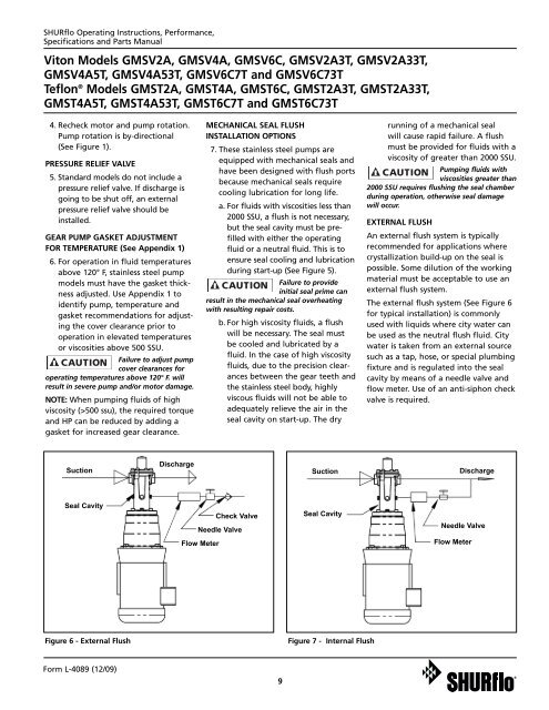
<strong>SHURflo</strong> Operating Instructions, Performance,Specifications and Parts ManualViton Models GMSV2A, GMSV4A, GMSV6C, GMSV2A3T, GMSV2A33T,GMSV4A5T, GMSV4A53T, GMSV6C7T and GMSV6C73TTeflon ® Models GMST2A, GMST4A, GMST6C, GMST2A3T, GMST2A33T,GMST4A5T, GMST4A53T, GMST6C7T and GMST6C73T4. Recheck motor and pump rotation.Pump rotation is by-directional(See Figure 1).PRESSURE RELIEF VALVE5. Standard models do not include apressure relief valve. If discharge isgoing to be shut off, an externalpressure relief valve should beinstalled.GEAR PUMP GASKET ADJUSTMENTFOR TEMPERATURE (See Appendix 1)6. For operation in fluid temperaturesabove 120° F, stainless steel pumpmodels must have the gasket thicknessadjusted. Use Appendix 1 toidentify pump, temperature andgasket recommendations for adjustingthe cover clearance prior tooperation in elevated temperaturesor viscosities above 500 SSU.Failure to adjust pumpcover clearances foroperating temperatures above 120° F. willresult in severe pump and/or motor damage.NOTE: When pumping fluids of highviscosity (>500 ssu), the required torqueand HP can be reduced by adding agasket for increased gear clearance.MECHANICAL SEAL FLUSHINSTALLATION OPTIONS7. These stainless steel pumps areequipped with mechanical seals andhave been designed with flush portsbecause mechanical seals requirecooling lubrication for long life.a. For fluids with viscosities less than2000 SSU, a flush is not necessary,but the seal cavity must be prefilledwith either the operatingfluid or a neutral fluid. This is toensure seal cooling and lubricationduring start-up (See Figure 5).Failure to provideinitial seal prime canresult in the mechanical seal overheatingwith resulting repair costs.b. For high viscosity fluids, a flushwill be necessary. The seal mustbe cooled and lubricated by afluid. In the case of high viscosityfluids, due to the precision clearancesbetween the gear teeth andthe stainless steel body, highlyviscous fluids will not be able toadequately relieve the air in theseal cavity on start-up. The dryrunning of a mechanical sealwill cause rapid failure. A flushmust be provided for fluids with aviscosity of greater than 2000 SSU.Pumping fluids withviscosities greater than2000 SSU requires flushing the seal chamberduring operation, otherwise seal damagewill occur.EXTERNAL FLUSHAn external flush system is typicallyrecommended for applications wherecrystallization build-up on the seal ispossible. Some dilution of the workingmaterial must be acceptable to use anexternal flush system.The external flush system (See Figure 6for typical installation) is commonlyused with liquids where city water canbe used as the neutral flush fluid. Citywater is taken from an external sourcesuch as a tap, hose, or special plumbingfixture and is regulated into the sealcavity by means of a needle valve andflow meter. Use of an anti-siphon checkvalve is required.SuctionDischargeSuctionDischargeSeal CavityCheck ValveNeedle ValveSeal CavityNeedle ValveFlow MeterFlow MeterFigure 6 - External FlushFigure 7 - Internal FlushForm L-<strong>4089</strong> (12/09)9