air handler installation instructions - Whirlpool HVAC Dealers
air handler installation instructions - Whirlpool HVAC Dealers
air handler installation instructions - Whirlpool HVAC Dealers

Create successful ePaper yourself
Turn your PDF publications into a flip-book with our unique Google optimized e-Paper software.
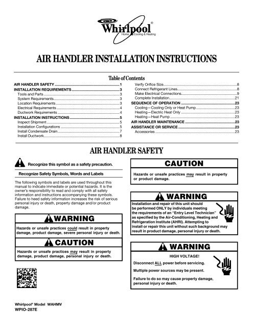
AIR HANDLER INSTALLATION INSTRUCTIONSAIR HANDLER SAFETY .................................................................1INSTALLATION REQUIREMENTS................................................3Tools and Parts ............................................................................3System Requirements..................................................................3Location Requirements................................................................3Electrical Requirements ...............................................................4Ductwork Requirements ..............................................................4INSTALLATION INSTRUCTIONS..................................................5Inspect Shipment .........................................................................5Installation Configurations ...........................................................5Install Condensate Drain..............................................................7Install Ductwork............................................................................8Recognize this symbol as a safety precaution.Recognize Safety Symbols, Words and LabelsThe following symbols and labels are used throughout thismanual to indicate immediate or potential hazards. It is theowner’s responsibility to read and comply with all safetyinformation and <strong>instructions</strong> accompanying these symbols.Failure to heed safety information increases the risk of seriouspersonal injury or death, property damage and/or productdamage.WARNINGHazards or unsafe practices could result in propertydamage, product damage, severe personal injury or death.Goodman 1CAUTIONHazards or unsafe practices may result in propertydamage, product damage, personal injury or death.Table of ContentsAIR HANDLER SAFETYVerify Orifice Size..........................................................................8Connect Refrigerant Lines............................................................8Make Electrical Connections........................................................9Complete Installation..................................................................21SEQUENCE OF OPERATION ......................................................23Cooling—Cooling Only or Heat Pump.......................................23Heating—Electric Heat Only ......................................................23Heating—Heat Pump .................................................................23AIR HANDLER MAINTENANCE ..................................................23ASSISTANCE OR SERVICE .........................................................23Accessories ................................................................................23CAUTIONGoodman 9Hazards or unsafe practices may result in propertyor product damage.WARNINGInstallation and rep<strong>air</strong> of this unit shouldbe performed ONLY by individuals meetingthe requirements Goodman of “Entry Level Technician” 7as specified by the Air-Conditioning, Heating andRefrigeration Institute (AHRI). Attempting toinstall or rep<strong>air</strong> this unit without such background mayresult in product damage, personal injury or death.WARNINGHIGH VOLTAGE!Goodman 6Disconnect ALL power before servicing.Multiple power sources may be present.Failure to do so may cause property damage,personal injury or death.<strong>Whirlpool</strong> ® Model WAHMVWPIO-287E
WARNINGGoodman 33This product is factory-shipped for use with 208/240/1/60electrical power supply. DO NOT reconfigure this <strong>air</strong><strong>handler</strong> to operate with any other power supply.WARNINGTo avoid property damage, personal injury or death due toelectrical shock, this unit MUST have an uninterrupted,unbroken electrical ground. The electrical ground circuitmay consist of an appropriately sized electrical wireconnecting the ground lug in the unit control box to thebuilding electrical serviceGoodmanpanel.34Other methods of grounding are permitted if performedin accordance with the National Electric Code (NEC)/American National Standards Institute (ANSI) /NationalFire Protection Association (NFPA) 70 and local/statecodes. In Canada, electrical grounding is to be inaccordance with the Canadian Electric Code (CSA) C22.1.CAUTIONWhen installing or servicing this equipment, safetyGoodman 35clothing, including hand and eye protection, is stronglyrecommended. If installing in an area that has specialsafety requirements (hard hats, etc.), observe theserequirements.WARNINGDo not connect Goodman to or use any device 36that is not designcertifiedfor use with this unit. Serious property damage,personal injury, reduced unit performance and/or hazardousconditions may result from the use of such non-approveddevices.WARNINGGoodman 37To prevent the risk of property damage, personal injury, ordeath, do not store combustible materials or use gasolineor other flammable liquids or vapors in the vicinity of thisunit.DANGERCARBON MONOXIDE POISONING HAZARDSpecial Warning for Installation of Furnace or Air HandlingUnits in Enclosed Areas such as Garages, Utility Rooms orParking Areas.Goodman 38Carbon monoxide producing devices (such as anautomobile, space heater, gas water heater, etc.) shouldnot be operated in enclosed areas such as unventilatedgarages, utility rooms or parking areas because of thedanger of carbon monoxide (CO) poisoning resulting fromthe exhaust emissions. If a furnace or <strong>air</strong> <strong>handler</strong> isinstalled in an enclosed area such as a garage, utility roomor parking area and a carbon monoxide producing device isoperated therein, there must be adequate, direct outsideventilation.This ventilation is necessary to avoid the danger of COpoisoning which can occur if a carbon monoxide producingdevice continues to operate in the enclosed area. Carbonmonoxide emissions can be (re)circulated throughout thestructure if the furnace or <strong>air</strong> <strong>handler</strong> is operating in anymode.CO can cause serious illness including permanent braindamage or death.IMPORTANT: The United States Environmental ProtectionAgency (EPA) has issued various regulations regarding theintroduction and disposal of refrigerants in this unit. Failure tofollow these regulations may harm the environment and can leadto the imposition of substantial fines. These regulations may varyby jurisdiction. A certified technician must perform the <strong>installation</strong>and service of this product. Should questions arise, contact yourlocal EPA office.This product is designed and manufactured to permit <strong>installation</strong>in accordance with national codes. It is the installer’sresponsibility to install this unit in accordance with national codesand/or prevailing local codes and regulations.2
These <strong>instructions</strong> are intended as a general guide only for use byqualified persons and do not supersede any national or localcodes in any way. Compliance with all local, state, or nationalcodes pertaining to this type of equipment should be determinedprior to <strong>installation</strong>.Read this entire instruction manual, as well as the <strong>instructions</strong>supplied in separate equipment, before starting the <strong>installation</strong>.All models are designed for indoor <strong>installation</strong> only.The <strong>installation</strong> of the <strong>air</strong> <strong>handler</strong>, field wiring, warm <strong>air</strong> ducts, etc.must conform to the requirements of the National ElectricalCode, ANSI/NFPA No. 70 (latest edition) in the United States, andany state laws, and local ordinances (including plumbing orwastewater codes). Local authorities having jurisdiction shouldbe consulted before <strong>installation</strong> is made. Such applicableregulations or requirements take precedence over the general<strong>instructions</strong> in this manual.Install the conditioned <strong>air</strong> plenum, ducts and <strong>air</strong> filters (notprovided) in accordance with NFPA 90B Standard for theInstallation of Warm Air Heating and Air-Conditioning Systems(latest edition).The <strong>air</strong> <strong>handler</strong> is provided with flanges for the connection of theplenum and ducts.Air filters (not provided) must be listed as Class 2 furnace <strong>air</strong>filters.The <strong>air</strong> <strong>handler</strong> can be used with R-410A from the factory.The <strong>air</strong> <strong>handler</strong> is shipped from the factory completelyassembled. Some models are configured for upflow <strong>air</strong> dischargeonly, and some models are configured for upflow or horizontalleft-hand <strong>air</strong> discharge. The <strong>air</strong> <strong>handler</strong> cabinet conforms to2 percent or less <strong>air</strong> leakage.Do not remove the cabinet knockouts until it has beendetermined which knockouts will need to be removed for the<strong>installation</strong>.Select the final <strong>installation</strong> position which best suits the siteconditions. Consider required clearances, space, routingrequirements for refrigerant line, condensate disposal, filters,ductwork, wiring, and accessibility for service. Refer to the <strong>air</strong><strong>handler</strong> rating plate on the <strong>air</strong> <strong>handler</strong> for specific information.Tools and PartsGather the required tools and parts before starting <strong>installation</strong>.Read and follow the <strong>instructions</strong> provided with any tools listedhere.Tools Needed■ ¹⁄₄" nut driver■ Level■ Screwdriver■ Adjustable wrench■■■INSTALLATION REQUIREMENTSTape measureHammerSealantParts NeededCheck local codes, check existing electrical supply, and read“Ductwork Requirements” and “Electrical Requirements” beforepurchasing parts.■■System RequirementsThe <strong>air</strong> <strong>handler</strong> is designed to match, and must be used withoutdoor units as rated. The indoor units are manufactured with aninterchangeable refrigerant metering orifice to provide optimumrefrigerant control and system performance with a variety ofdifferent capacities of outdoor units.In some cases, the rating of the outdoor unit may require that the<strong>air</strong> <strong>handler</strong> coil assembly orifice be changed to obtain ratedperformance.Location RequirementsNOTE: When used on cooling applications, excessive sweatingmay occur when the <strong>air</strong> <strong>handler</strong> is installed in a very humidspace.■■■■UL listed wire connectorsReplacement orifice (if needed). See “Verify Orifice Size.” Thecorrect orifice size may be contained in the replacementorifice package located inside the control box of the outdoorunit. If this package does not contain the correct orifice foryour <strong>air</strong> <strong>handler</strong>, you must purchase the correct orifice size.If the <strong>air</strong> <strong>handler</strong> is installed in an unconditioned space,sealant should be applied around the electrical wires,refrigerant tubing, and condensate lines where they enter thecabinet.Electrical wires should be sealed on the inside where they exitthe conduit opening. Sealant is required to avoid <strong>air</strong> leakageand condensate from forming inside the <strong>air</strong> <strong>handler</strong>, controlbox, and on the electrical controls.The <strong>air</strong> <strong>handler</strong> must be installed in such a way as to allowfree access to the coil/filter compartment and blower/controlcompartment.The <strong>air</strong> <strong>handler</strong> must be installed in a level position to ensureproper condensate drainage.Installation ClearancesNon-Duct Return Closet InstallationThe <strong>air</strong> <strong>handler</strong> can be installed in a closet with a false bottom toform a return <strong>air</strong> plenum or be installed with a return <strong>air</strong> plenumunder the <strong>air</strong> <strong>handler</strong>.Louvers or return <strong>air</strong> grilles are field supplied. Local codes maylimit the application of systems without a duct return to singlestorybuildings.3
■For an <strong>air</strong> <strong>handler</strong> installed in a closet with a louvered returnopening, the minimum open area for the louvers will be asshown below.18" and 24" (45.7 cm and61 cm) models30" and 36" (76.2 cm and91.4 cm) models42", 48" and 60" (106.7 cm,121.9 cm and 152.4 cm) models■ If the free area is not known, assume a 25% free area forwood louvers or a 75% free area for metal louvers or grilles.■ Using the louver dimensions and the 25% or 75%assumption, determine if the louver open area meets theminimum open area listed in the previous chart.■ If the return <strong>air</strong> plenum is used, the return <strong>air</strong> grille should beimmediately in front of the opening in the plenum to allow forthe free flow of return <strong>air</strong>.■ When the <strong>air</strong> <strong>handler</strong> is not installed in front of the opening,there must be adequate clearance around the <strong>air</strong> <strong>handler</strong> toallow for the free flow of return <strong>air</strong>.■ The unit clearance from a combustible surface may be 0".■ Allow a minimum of 24" (61 cm) in front of the unit for serviceclearance.■ Do not install the <strong>air</strong> <strong>handler</strong> in a location that violates the<strong>instructions</strong> provided with the condenser.■ If the unit is located in an area with high ambient temperatureand/or high humidity, the <strong>air</strong> <strong>handler</strong> may have condensationon the casing. On these <strong>installation</strong>s, a wrap of 2" (5.1 cm)fiberglass insulation with a vapor barrier is recommended.■ Consult all appropriate regulatory codes prior to determiningfinal clearances.■ When installing this unit in an area that may become wet,elevate the unit with a sturdy, non-porous material.■ In <strong>installation</strong>s that may lead to physical damage (forexample, in a garage) it is recommended that a barrier beinstalled to avoid such damage.Electrical Requirements320 sq. in. (2,065 cm 2 )360 sq. in. (2,323 cm 2 )450 sq. in. (2,903 cm 2 )WARNINGTo avoid the Goodman risk of injury, electrical 31shock or death, thefurnace must be electrically grounded in accordance withlocal codes or, in their absence, with the latest edition of theNational Electric Code (NEC).NOTES:■ Use copper conductors only.■ All field wiring must be done in accordance with NationalElectrical Code, applicable requirements of UL and localcodes where applicable.■ Electrical wiring, disconnect means and overcurrentprotection are to be supplied by the installer. Refer to the <strong>air</strong><strong>handler</strong> rating plate for maximum overcurrent protection,minimum circuit ampacity, as well as operating voltage.■ The power supply must be sized and protected according tothe specifications supplied on the product.■ This <strong>air</strong> <strong>handler</strong> is factory-configured for 240-volt, singlephase, 60 cycles. For 208-volt applications, see “208-VoltConversion” in the “Make Electrical Connections” section.■ For optional electric heater applications, see “Accessories.”Refer to the <strong>instructions</strong> provided with the accessory forproper <strong>installation</strong>.■■■■■■Ductwork RequirementsInstall the conditioned <strong>air</strong> plenum, ducts and <strong>air</strong> filters (notprovided) in accordance with NFPA 90B Standard for theInstallation of Warm Air Heating and Air-ConditioningSystems (latest edition).The <strong>air</strong> <strong>handler</strong> is provided with flanges for the connection ofthe plenum and ducts.The <strong>air</strong> <strong>handler</strong> is equipped with flanges that can form a filterrack for the <strong>installation</strong> of the <strong>air</strong> filter, or the filter may beinstalled as part of the return <strong>air</strong> duct system.Air filters must be listed as Class 2 furnace <strong>air</strong> filters.CAUTIONDo not operate this product without all the ductworkattached.Goodman 39Supply and return ductwork must be adequately sized tomeet the system’s <strong>air</strong> requirements and static pressurecapabilities. To ensure correct system performance, theductwork is to be sized to accommodate 375 to 425 CFM perton of cooling with the static pressure not to exceed 0.5"W.C. Ductwork should be insulated with a minimum of 1"(2.5 cm) thick insulation with a vapor barrier in conditionedareas or 2" (5.1 cm) minimum in unconditioned areas.Supply plenum should be the same size as the flangedopening provided around the blower outlet and shouldextend ideally at least 36" (91.4 cm) from the <strong>air</strong> <strong>handler</strong>before turning or branching off plenum into duct runs. Theplenum forms an extension of the blower housing andminimizes <strong>air</strong> expansion losses from the blower.4
INSTALLATION INSTRUCTIONSInspect ShipmentThese <strong>air</strong> <strong>handler</strong>s are completely factory assembled, and allcomponents are performance tested. Each <strong>air</strong> <strong>handler</strong> consists ofa blower assembly, refrigerant coil, and controls, in an insulatedgalvanized steel factory finished enclosure. Knockouts areprovided for electrical wiring entrance.■ Check the <strong>air</strong> <strong>handler</strong> rating plate to confirm specificationsare as ordered.■ Upon receipt of <strong>air</strong> <strong>handler</strong>, thoroughly inspect it for possibleshipping damage. Closely examine the <strong>air</strong> <strong>handler</strong> inside thecarton if the carton is damaged.■ If damage is found, it should be noted on the carrier’s freightbill. Damage claims should be filed with the carrierimmediately. Claims of shortages should be filed with theseller within 5 days.NOTE: If any damages are discovered and reported to the carrier,do not install the <strong>air</strong> <strong>handler</strong> because your claim may be denied.Return Air FiltersEach <strong>installation</strong> must include a return <strong>air</strong> filter. This filtering maybe performed at the <strong>air</strong> <strong>handler</strong> or externally such as a return <strong>air</strong>filter grille. Air <strong>handler</strong>s mounted in the downflow orientation,including “B” series, require external filtering. A washable filter isavailable as an accessory. To ensure optimum performance,frequent filter cleaning is advised.WAHMV Filter Number Quantity Required1830 FIL 36-42 131374260FIL 48-61 1Horizontal InstallationsHorizontal <strong>installation</strong>s can be left-hand or right-hand <strong>air</strong> supply.Adequate support must be provided to ensure cabinet integrity.Ensure that there is adequate room to remove, service andaccess panels if installing in the horizontal position. For thecorrect horizontal coil <strong>installation</strong>, see “Installation ConfigurationOptions” later in this section.IMPORTANT:■ This coil is provided with a secondary drain that should betrapped and piped to a location that will give the occupant avisual warning that the primary drain is clogged. See “InstallCondensate Drain.”■ When an evaporator coil is installed in an attic or above afinished ceiling, an auxiliary drain pan should be providedunder the <strong>air</strong> <strong>handler</strong> as specified by most local buildingcodes.Suspended Cabinet InstallationNOTE: Air <strong>handler</strong>s cannot be installed horizontally lying on orsuspended from either the front or back of the <strong>air</strong> <strong>handler</strong>. It mustbe positioned with one side parallel to the floor when in thehorizontal position.The suspending means must be field fabricated, and shouldconsist of 2 “cradles” made by attaching 2 rods to a length ofangle iron or suitable gauge steel.Installation Configuration Options—UpflowNOTES:■ As shipped from the factory.■ Return in bottom.■ Shading indicates proper line connections.Installation ConfigurationsFor ease in <strong>installation</strong>, it is best to make any necessary coilconfiguration changes before setting the <strong>air</strong> <strong>handler</strong> in place. See“Installation Configuration Options.”■■Upflow <strong>air</strong> discharge contains only 1 drain pan.Upflow or horizontal <strong>air</strong>flow contains 2 drain pans.Vertical InstallationsUpflowThe <strong>air</strong> <strong>handler</strong> must be supported on the bottom only and set ona field-supplied supporting frame with an <strong>air</strong> return opening.Securely attach the <strong>air</strong> <strong>handler</strong> to the supporting frame.ABA. Horizontal drain connections(left or right hand)ACB. Upflow drain connectionC. Bottom/filter frame5
Installation Configuration Options—Horizontal RightNOTES:■ Left to right <strong>air</strong>flow■ As shipped from the factoryInvert Air HandlerABCDrainsDEABCFA. Drain connectionsB. Coil access coverC. Blower access coverA. Access panelB. Return <strong>air</strong> side of unitC. Rear channel bracketD. Zee coil support bracketE. Coil retaining bracketF. Tie bracketInstallation Configuration Options—Horizontal LeftNOTES:■ Right to left <strong>air</strong>flow■ Requires drain pan location change.8. Install the zee coil supports and the wrapper stiffeners.9. Install the tie bracket.10. Install the rear channel bracket.11. To avoid possible condensate “blow off,” the insulationretainers are to be laid into the evaporator coil pan as shownin the “Evaporator Coil Pan” illustration.Evaporator Coil PanDrainsABA. Blower access coverB. Coil access coverC. Drain connectionsCDownflow ConversionConversion to downflow must be performed in an area thatallows access to all sides prior to placing the <strong>air</strong> <strong>handler</strong> in itsfinal location. To keep the evaporator coil pan from sweating, theDPI accessory insulation kit is to be used when performing thisconversion.NOTE: The DPI kit is not supplied with this product and is to bepurchased separately. See the following chart for the correct DPIkit.WAHMV ModelInsulation KitTo complete the conversion, slide the evaporator coil into thechassis and attach the 3 access panels.Evaporator CoilA. 3" (7.6 cm) flat insulation retainer (both sides)ABA1830 DPI36-42/203036/3137/4260 DPI48-61/201. Before inverting the <strong>air</strong> <strong>handler</strong>, remove all access panels, thecoil rear channel bracket, and the filter close-off panel.2. Remove the evaporator coil and the horizontal drain pan.3. Discard the horizontal drain pan.4. Install the plastic plug (provided) into the vacated accesspanel.5. Remove the 2 zee coil support brackets and insulationretaining brackets.6. Remove the tie bracket.7. Install the DPI Insulation Kit onto the bottom of the drain pan.CDEFA. WrapperB. Insulation jacketC. Zee coil supportD. Wrapper stiffenerE. Drain pan insulation kitF. Blower assembly6
NOTE: When the <strong>air</strong> <strong>handler</strong> is converted to the downflowposition, the coil may protrude above the cabinet on somemodels.Horizontal ConversionThe only field modification required for conversion to “HorizontalRight-Hand” is the removal of the plastic knockouts in thehorizontal panel drain connections. To keep the horizontal drainpan from sweating in high humidity applications, it isrecommended that a DPIH insulation accessory kit be used.NOTE: The DPIH insulation kit is not supplied with this productand should be purchased separately. See the following chart forthe correct DPIH kit.WAHMV ModelInsulation Kit10. Install the “J” bracket removed in Step 2 to support theupflow pan to the tie channel.11. Attach all panels and the metering device.WAHMV Motor OrientationIf the unit is in the upflow position, there is no need to rotate themotor. If the unit is in the downflow position, loosen the motormount and rotate the motor as shown in the following illustration.Check that the motor is oriented with the female connectionsfacing down on the casing. If the motor is not oriented with theconnections down, water will collect in the motor and may causepremature failure.ABN/ADPIH18-321830 DPIH36-423036/3137/4260 DPIH48-61The following describes converting to “Horizontal Left-Hand.”Conversion to downflow must be performed in an area thatallows access to all sides prior to placing the <strong>air</strong> <strong>handler</strong> in itsfinal location.DHorizontal Left-Hand ConversionCA. Front viewB. Side viewC. Female connectionsD. Use mounting bolts for optional ground.Achieving 2% Low Leakage RateA. DPIH kitB. Secondary drainC. Primary drain1. Remove the 3 <strong>air</strong> <strong>handler</strong> access panels.2. Remove the “J” shaped bracket that retains the evaporatorcoil.3. Remove the flowrator from the lower left side access paneland slide out the evaporator coil and horizontal drain pan.4. Remove the gasket from the horizontal pan drainconnections.5. Remove the oval shaped plastic plug from the left sideaccess panel.6. Remove the oval shaped rubber gasket seal from the lowerright side access panel.7. The drain connections for the horizontal pan are sealed with athin coating of plastic. Knock out this plastic seal with ascrewdriver and hammer.NOTE: The upper drain will become the secondary drainwhich is mandatory in many municipalities.8. Install the plastic plug removed in Step 5 to the right sidelower access panel and the oval shaped rubber gasket to thelower left access panel.9. Reinstall the evaporator coil with the horizontal panel on theleft side.NOTE: Push the assembly completely to the rear to ensurethe engagement of the upflow pan with the rear channelbracket.AB CEnsure that the Neoprene gasket with PSA remains intact on allsurfaces that the access panels are secured to. These surfacesare the entire length of the wrapper and areas between the uppertie plate, upper and lower access panels. Check that the upperaccess panel breaker insert gasket is intact and that the flowratorgasket is installed on the lower access panel. An additional drainhole cover is required.Install Condensate DrainCAUTIONIf secondary drain is not installed, the secondary accessmust be plugged. Goodman 2The <strong>air</strong> <strong>handler</strong> is provided with ³⁄₄" (1.9 cm) NPT condensatedrain connections.A field-fabricated secondary drain pan, with a drainpipe to theoutside of the building, is required in all <strong>installation</strong>s over afinished living space or in any area that may be damaged byoverflow from the main drain pan. In some localities, local codesmay require a secondary drain pan for any horizontal <strong>installation</strong>.Make sure the <strong>air</strong> <strong>handler</strong> is level so that the drain pan will emptycompletely.1. Remove the appropriate drain knockouts. See “InstallationConfigurations.” You may need to remove the indoor coilassembly from the cabinet.2. Remove any web from inside any threaded drain pan hole towhich a drain line is to be connected. Gently remove the webso as not to damage the coil.7
3. Connect the primary drain line connection to the primarydrain pan connection. The primary drain connection is flushwith the bottom of the inside of the pan. The secondaryconnection is raised above the bottom of the inside of thepan.NOTE: When making drain fitting connections to the drainpan, hand tighten. Using a sealant is recommended.Overtightening the fittings can split connections on the drainpan.4. Secondary drain connections, if used, should be connectedto a separate drainage system. Run the secondary drain lineto a place where the occupant would notice water comingfrom the secondary drain.5. Install a 3" (7.6 cm) trap in both the primary and secondarydrain lines as close to the unit as practical. Make sure the topof the trap is below the connection to the drain pan to allowcomplete drainage of the pan.NOTE: Horizontal runs must also have an anti-siphon <strong>air</strong> vent(standpipe) installed ahead of the horizontal run. See “TypicalCondensate Drain Connection” in this section. An extremelylong horizontal run may require an oversized drain line toeliminate the trapping of <strong>air</strong>.Typical Condensate Drain Connection(Secondary Drain Not Shown)3. Correct any leaks found.Install DuctworkIMPORTANT:■ Install the ductwork in accordance with NFPA 90B Standardfor the Installation of Warm Air Heating and Air-ConditioningSytems (latest edition) and any local codes.■ Connect the supply <strong>air</strong> duct to the flange on top of the unit. Ifan isolation connector is used, it must be nonflammable.■ A return <strong>air</strong> duct system is recommended. If the unit isinstalled in a confined space or closet, the entire duct crosssectional area must meet the minimum return <strong>air</strong> free area.Verify Orifice Size1. Consult the outdoor unit literature to determine whether theindoor unit has the correct orifice installed.2. If a change of the orifice is required, loosen the brass hex nutand separate the orifice extension stub from the brass hexfitting.ABCDAA. Air <strong>handler</strong>B. Drain connectionC. Drain lineD. 2" (5.1 cm) minimumE. Anti-siphon <strong>air</strong> ventIF. 3" (7.6 cm) minimumG. Drain trapH. Auxiliary drain panI. 12" (30.5 cm) maximumNOTE: Do not operate the <strong>air</strong> <strong>handler</strong> without a drain trap. Thecondensate drain is on the negative pressure side of the blower;therefore, <strong>air</strong> being pulled through the condensate line will blockpositive drainage without a proper trap.6. Route the drain line to the outside or to an appropriate drain.Drain lines must be installed so they do not block serviceaccess to the front of the <strong>air</strong> <strong>handler</strong>. A 24" (61 cm) clearanceis required for filter, coil, or blower removal and serviceaccess.NOTE: Check local codes before connecting the drain line toan existing drainage system.7. Insulate the drain lines where sweating could cause waterdamage.Test Condensate Drain Pan and Drain Line AfterInstallation:1. Pour several quarts of water into the drain pan, enough to fillthe drain trap and line.2. Check that the drain pan is draining completely, no leaks arefound in the drain line fittings, and water is draining from theend of the primary drain line.DHFBCEG3. Remove the orifice with an orifice extractor tool.4. Insert the proper orifice into the fitting, seal end first. Makesure the orifice is free to move in the fitting.5. Replace the brass hex nut.NOTE: Overtightening the brass hex nut will crush the gasketand may result in a system leak or stuck piston.6. Dispose of/recycle all packaging and unused parts.Connect Refrigerant LinesRefrigerant lines must be connected by a licensed, EPA certifiedrefrigerant technician in accordance with established procedures.IMPORTANT:■■■GA. Distributor fittingB. Piston orificeC. Ring seal (supplied)D. Orifice extension stubE. 0.812" brass hex nutF. Brass hex fittingG. Mounting flangeConnecting refrigerant lines must be clean, dehydrated,refrigerant-grade copper lines. Air <strong>handler</strong> coils should beinstalled only with specified line sizes for approved systemcombinations.Handle the refrigerant lines gently during the <strong>installation</strong>process. Sharp bends or possible kinking in the lines willcause a restriction.Do not remove the caps from the lines or system connectionpoints until connections are ready to be completed.WARNINGGoodman 4This product is factory-shipped under pressure. Followthese <strong>instructions</strong> to prevent injury.FE8
CAUTIONTo protect the unit when Goodman welding close to 3the paintedsurfaces, the use of a quenching cloth is strongly advisedto prevent scorching or marring of the equipment finish.Solder with a minimum of 5% silver is recommended.Tubing PreparationAll cut ends are to be round, burr free and clean. Failure to followthis practice increases the chances for refrigerant leaks. Thesuction line is spun closed and requires pipe cutters to removethe closed end.CAUTIONGoodman 8Excessive torque can cause orifices to stick. Use theproper torque settings when tightening orifices.11. Torque the ¹³⁄₁₆" nut to 10 to 30 ft-lbs. or tighten one-sixthturn.12. Replace the suction line, grommet and insulation.ABCGPost BrazingQuench all welded joints with water or a wet rag.DEFPiping SizeFor the correct tubing size, follow the specification for thecondenser/heat pump.A. TailpieceB. ¹³⁄₁₆" nutC. Plastic or brass capD. White Teflon ® sealE. PistonF. Rubber grommetG. Suction line withspin closureSpecial InstructionsThis coil comes equipped with a check style flowrator forrefrigerant management. For most <strong>installation</strong>s with matchingapplications, no change to the flowrator piston is required.However, in mix-matched applications, a flowrator piston changemay be required. See the piston kit chart or consult your localdistributor for details regarding mix-matched piston sizing. If themix-match application requires a different piston size, change thepiston in the flowrator on the indoor coil before installing the coiland follow the procedure shown below.IMPORTANT: Torch heat required to braze tubes of various sizesis proportional to the size of the tube. Tubes of smaller sizerequire less heat to bring the tube to brazing temperature beforeadding brazing alloy. Applying too much heat to any tube canmelt the tube. Service personnel must use the appropriate heatlevel for the size of the tube being brazed.NOTE: The use of a heat shield when brazing is recommended toavoid burning the serial plate or the finish on the unit. Heat trap orwet rags should be used to avoid damage to heat-sensitivecomponents such as service valves and TXV valves.1. Loosen the ¹³⁄₁₆" nut one turn only to allow high pressuretracer gas to escape. No gas indicates a possible leak.2. After the gas has escaped, remove the nut and discard theblack or brass cap.3. Remove the check piston to verify it is correct and thenreplace the piston. See the piston kit chart in the <strong>instructions</strong>.4. Use a tube cutter to remove the spin closure on the suctionline.5. Remove the tailpiece clamped to the exterior and slide the¹³⁄₁₆" nut into place.6. Braze the tailpiece to the line set liquid tube.7. Insert the suction line into the connection.8. Slide the insulation and the rubber grommet at least 18"(45.7 cm) away from the braze joint.9. Braze suction line.10. After the tailpiece has cooled, confirm position of the whiteTeflon ® seal and hand tighten the ¹³⁄₁₆" nut.240-Volt InstallationsMake Electrical ConnectionsWARNINGHIGH VOLTAGE!Disconnect ALL power before servicing.Goodman 6Multiple power sources may be present.Failure to do so may cause property damage,personal injury or death.WARNINGTo avoid the risk of fire or equipment damage, usecopper conductors.Goodman 22WARNINGTo avoid property damage, personal injury or death due toelectrical shock, this unit MUST have an uninterrupted,unbroken electrical ground. Goodman The electrical 34 ground circuitmay consist of an appropriately sized electrical wireconnecting the ground lug in the unit control box to thebuilding electrical service panel.Other methods of grounding are permitted if performedin accordance with the National Electric Code (NEC)/American National Standards Institute (ANSI) /NationalFire Protection Association (NFPA) 70 and local/statecodes. In Canada, electrical grounding is to be inaccordance with the Canadian Electric Code (CSA) C22.1.9
1. Disconnect all power supplies.2. Remove the blower access panel.3. Route the field supply wires to the <strong>air</strong> <strong>handler</strong> electricalconnection box.4. Using UL-Listed wire connectors, connect the field supplywires to the <strong>air</strong> <strong>handler</strong> (black to black and yellow to yellow).208-Volt ConversionWARNINGHIGH VOLTAGE!Goodman 6Disconnect ALL power before servicing.Multiple power sources may be present.Failure to do so may cause property damage,personal injury or death.5. Connect the ground wire to the ground terminal marked“GND.”6. Replace the blower access panel.1. Disconnect all power supplies.2. Remove the <strong>air</strong> <strong>handler</strong> access panel.3. Move the 2 connected black transformer leads from the240-volt terminal on the transformer to the 208-volt terminalon the transformer. See “Wiring Diagram—Electric Heat andBlower” in the “Make Electrical Connections” section.Electric HeatRefer to this manual in combination with the <strong>instructions</strong>provided with the heat kit for the correct <strong>installation</strong> procedure.The <strong>air</strong> <strong>handler</strong>s listed in this manual do not have factory installedelectric heat. Electric heat is available as an accessory. If you areinstalling this option, the only heat kits that can be used are theHKR series.NOTE: The EHK, ECB, EDB and EDK kits are not approved foruse with these <strong>air</strong> <strong>handler</strong>s.The heating mode temperature rise is dependent upon thesystem <strong>air</strong>flow, the supply voltage, and the heat kit size (kW)selected. Use the Temperature Rise tables to determine thetemperature rise ºF (ºC).Temperature Rise Table ºF—230/1/60 Supply VoltageHeat Kit Nominal kW—ºF (ºC)CFM3 (-16.1) 5 (-15) 6 (-14.4) 8 (-13.3) 10 (-12.2) 15 (-9.4) 20 (-6.7) 21 (-6.1)600 18 (-7.8) 28 (-2.2) 35 (1.7) 41 (5)800 13 (-10.6) 21 (-6.1) 26 (-3.3) 31 (-0.6) 42 (5.6)1,000 11 (-11.7) 17 (-8.3) 21 (-6.1) 25 (-3.9) 34 (1.1) 50 (10)1,200 9 (-12.8) 14 (-10) 18 (-7.8) 21 (-6.1) 28 (-2.2) 42 (5.6) 56 (13.3) 62 (16.7)1,400 8 (-13.3) 12 (-11.1) 15 (-9.4) 18 (-7.8) 24 (-4.4) 36 (2.2) 48 (8.9) 53 (11.7)1,600 7 (-13.9) 10 (-12.2) 13 (-10.6) 15 (-9.4) 21 (-6.1) 31 (-0.6) 42 (5.6) 46 (7.8)1,800 6 (-14.4) 9 (-12.8) 12 (-11.1) 14 (-10) 19 (-7.2) 28 (-2.2) 37 (2.8) 41 (5)2,000 5 (-15) 8 (-13.3) 11 (-11.7) 12 (-11.1) 17 (-8.3) 25 (-3.9) 34 (1.1) 37 (2.8)10
Temperature Rise Table ºF—220/1/60 Supply VoltageHeat Kit Nominal kW—ºF (ºC)CFM3 (-16.1) 5 (-15) 6 (-14.4) 8 (-13.3) 10 (-12.2) 15 (-9.4) 20 (-6.7) 21 (-6.1)600 17 (-8.3) 27 (-2.8) 34 (1.1) 39 (3.9)800 13 (-10.6) 20 (-6.7) 25 (-3.9) 30 (-1.1) 40 (4.4)1,000 10 (-12.2) 16 (-8.9) 20 (-6.7) 24 (-4.4) 32 (0) 48 (8.9)1,200 8 (-13.3) 13 (-10.6) 17 (-8.3) 20 (-6.7) 27 (-2.8) 40 (4.4) 53 (11.7) 59 (15)1,400 7 (-13.9) 11 (-11.7) 14 (-10) 17 (-8.3) 23 (-5) 34 (1.1) 46 (7.8) 51 (10.6)1,600 6 (-14.4) 10 (-12.2) 13 (-10.6) 15 (-9.4) 20 (-6.7) 30 (-1.1) 40 (4.4) 44 (6.7)1,800 6 (-14.4) 9 (-12.8) 11 (-11.7) 13 (-10.6) 18 (-7.8) 27 (-2.8) 36 (2.2) 39 (3.9)2,000 5 (-15) 8 (-13.3) 10 (-12.2) 12 (-11.1) 16 (-8.9) 24 (-4.4) 32 (0) 35 (1.7)Temperature Rise Table ºF—208/1/60 Supply VoltageHeat Kit Nominal kW—ºF (ºC)CFM3 (-16.1) 5 (-15) 6 (-14.4) 8 (-13.3) 10 (-12.2) 15 (-9.4) 20 (-6.7) 21 (-6.1)600 16 (-8.9) 25 (-3.9) 32 (0) 37 (2.8)800 12 (-11.1) 19 (-7.2) 24 (-4.4) 30 (-1.1) 38 (3.3)1,000 10 (-12.2) 15 (-9.4) 19 (-7.2) 22 (-5.6) 30 (-1.1) 46 (7.8)1,200 8 (-13.3) 13 (-10.6) 16 (-8.9) 19 (-7.2) 25 (-3.9) 38 (3.3) 51 (10.6) 56 (13.3)1,400 7 (-13.9) 11 (-11.7) 14 (-10) 16 (-8.9) 22 (-5.6) 33 (0.6) 43 (6.1) 48 (8.9)1,600 6 (-14.4) 9 (-12.8) 12 (-11.1) 14 (-10) 19 (-7.2) 28 (-2.2) 38 (3.3) 42 (5.6)1,800 5 (-15) 8 (-13.3) 11 (-11.7) 12 (-11.1) 17 (-8.3) 25 (-3.9) 34 (1.1) 37 (2.8)2,000 5 (-15) 8 (-13.3) 10 (-12.2) 11 (-11.7) 15 (-9.4) 23 (-5) 30 (-1.1) 34 (1.1)NOTE: For <strong>installation</strong>s not indicated in the Temperature Risetables, the following formula is to be used:TR = (kW x 3412) x (Voltage Correction) / (1.08 x CFM)Where: TR =kW =Temperature RiseHeater Kit Actual kW3412 = Btu per kWNOTE: The Temperature Rise Tables can also be used todetermine the <strong>air</strong> <strong>handler</strong> <strong>air</strong>flow delivery. When using thesetables for this purpose, set the room thermostat to maximumheat and allow the system to reach steady state conditions.Insert 2 thermometers, one in the return <strong>air</strong> and one in the supply<strong>air</strong>. The temperature rise is the supply <strong>air</strong> temperature minus theroom <strong>air</strong> temperature.Use HKR specification sheets to determine the HKR available fora given <strong>air</strong> <strong>handler</strong>.Voltage Correction =96 (230 Supply Volts)= 92 (220 Supply Volts)= 87 (208 Supply Volts)1.08 = ConstantCFM =Measured Airflow11
WARNINGHIGH VOLTAGE!Disconnect ALL power before servicing.Goodman 6 Long - top of each pageMultiple power sources may be present.Failure to do so may cause property damage, personal injury or death.Cooling Only—2-Stage Heat ThermostatRoom ThermostatFor Heat PumpUse OnlyOCondensingUnitW1W2 C R G YIf NeededHumidistat(Optional)To Comfort AlertModule (If Used)THERMOSTATSHUMIDISTATE\W1W\W2 O OTC OT1 OT2 C R Y1 G Y/Y2 HUMSee Note 5See Note 3OUTDOORR YCON COM O W2 EDY1See Note 5W1OT1OT2HUMPlease referto manualfor properDIP switch (CFM)configuration.W2W1 W2 C RHEATER 24 VACDIP SWITCHONOFF2 nd Stage Heater1 st Stage HeaterNOTES:1. Y/Y2 enables high speed fan cooling.2. E/W1 enables low speed fan heating. W/W2 enables highspeed fan heating.3. OT1 PJ4 must be cut for this configuration.4. DIP Switch 4 must be in the “ON” position.5. Cut HUM PJ6 jumper if using humidistat. STAT opens onhumidity rise.Cooling Only—2-Stage Heat—1 st —Room Thermostat, 2 nd —Outdoor ThermostatFor Heat PumpUse OnlyOOutdoor ThermostatRoom ThermostatW C R G YCondensingUnitIf NeededHumidistat(Optional)To Comfort AlertModule (If Used)E\W1 W/W2THERMOSTATSO OTC OT1 OT2R CY1GY/Y2HUMIDISTATHUMSee Note 5See Note 3ROUTDOORHEATPUMPYCON COM O W2 EDY1See Note 5OT1OT2W1W2W1 W2HEATERSWITCHC R24 VACHUMPlease referto manualfor properDIP switch (CFM)configuration.DIPONOFF2 nd Stage Heater1 st Stage HeaterNOTES:1. Y/Y2 enables high speed fan cooling.2. E/W1 enables low speed fan heating. E/W1 with outdoorthermostat closed enables high speed fan heating.3. OT1 PJ4 must be cut for this configuration.4. DIP Switch 4 must be in the “ON” position.5. Cut HUM PJ6 jumper if using humidistat. STAT opens onhumidity rise.12
WARNINGHIGH VOLTAGE!Disconnect ALL power before servicing.Goodman 6 Long - top of each pageMultiple power sources may be present.Failure to do so may cause property damage, personal injury or death.Cooling Only—2-Stage Heat—Outdoor Thermostat EnabledFor Heat PumpUse OnlyOOutdoor ThermostatRoom ThermostatW1 W2 C R GYCondensingUnitIf NeededHumidistat(Optional)To Comfort AlertModule (If Used)THERMOSTATSE\W1 W/W2 O OTC OT1 OT2Y1GY/Y2HUMIDISTATHUMSee Note 6See Note 3See Note 4OUTDOORCONDENSER HEAT PUMPYCON COM O W2 EDY1See Note 6OT1OT2W1W2W1 W2HEATERSWITCH24 VACHUMPlease referto manualfor properDIP switch (CFM)configuration.DIPONOFF2 nd Stage Heater1 st Stage HeaterNOTES:■ 1 st Stage auxiliary heat enabled by room thermostat.■ 2 nd Stage auxiliary heat enabled by room thermostat andclosed OT2.1. Y/Y2 enables high speed fan cooling.2. E/W1 enables low speed fan heating. W/W2 with outdoorthermostat closed enables high speed fan heating.3. OT1 PJ4 must be cut for this configuration.4. OT2 PJ2 must be cut for this configuration.5. DIP Switch 4 must be in the “ON” position.6. Cut HUM PJ6 jumper if using humidistat. STAT opens onhumidity rise.Heat Pump with 1-Stage Emergency Heat and 1 Stage Auxiliary HeatHeat PumpR Y C O W2Room ThermostatE W2 O C R G YHEATPUMPR YCON COM O W2 EDIf NeededHumidistat(Optional)See Note 5THERMOSTATSE\W1 W/W2 O OTC OT1 OT2 C ROUTDOORHEATPUMPY1GHUMIDISTATY/Y2 HUMRemoveProductionWire Y1-OSee Note 3RYCON COM O W2 EDW1 W2HEATERC R24 VACY1See Note 6OT1OT2W1W2SWITCHSee Note 5HUMPlease referto manualfor properDIP switch (CFM)configuration.DIPONOFF1 st Stage HeaterNOTES:1. Y enables high speed fan cooling.2. E and W2 enable high speed fan heating.3. If OT2 PJ2 is cut, E and W2 enable low speed fan heating.4. DIP Switch 4 must be in the “ON” position.5. Cut HUM PJ6 jumper if using humidistat. STAT opens onhumidity rise.6. Remove orange Jumper Wire Y1-O.13
WARNINGHIGH VOLTAGE!Disconnect ALL power before servicing.Goodman 6 Long - top of each pageMultiple power sources may be present.Failure to do so may cause property damage, personal injury or death.Heat Pump with 2-Stage Emergency Heat and 1-Stage Auxiliary HeatHeat PumpR Y C O W2Room ThermostatE W2 O C R G YHEATPUMPR YCON COM O W2 EDIf NeededHumidistat(Optional)See Note 5THERMOSTATSE\W1 W/W2 O OTC OT1 OT2 C ROUTDOORHEATPUMPY1GHUMIDISTATY/Y2 HUMRemoveProductionWire Y1-OSee Note 3RYCON COM O W2 EDW1 W2HEATERC R24 VACY1See Note 6OT1OT2W1W2SWITCHSee Note 5HUMPlease referto manualfor properDIP switch (CFM)configuration.DIPONOFF2 nd Stage Heater1 st Stage HeaterNOTES:1. Y enables high speed fan cooling.2. E enables low speed fan heating. W2 enables low speed fanheating. W2 and OT2 closed enable high speed fan heating.3. OT2 PJ2 must be cut for this configuration.4. DIP Switch 4 must be in the “ON” position.5. Cut HUM PJ6 jumper if using humidistat. STAT opens onhumidity rise.6. Remove orange Jumper Wire Y1-O.Heat Pump with 2-Stage Emergency Heat, 2-Stage Auxiliary Heat and 1 Outdoor ThermostatHeat PumpOutdoor ThermostatRoom ThermostatW2W2OIf NeededHumidistat(Optional)See Note 5E\W1 W/W2OGY/Y2RemoveProductionWire Y1-OOSee Note 6See Note 3SWITCHSee Note 5Please referto manualfor properDIP switch (CFM)configuration.DIPONOFF2 nd Stage Heater1 st Stage HeaterNOTES:■ 1 st Stage auxiliary heat enabled by room thermostat.■ 2 nd Stage auxiliary heat enabled by room thermostat andoutdoor thermostat.1. Y enables high speed fan cooling.2. E enables low speed fan heating. W2 enables high speed fanheating.3. OT1 PJ4 must be cut for this configuration.4. DIP Switch 4 must be in the “ON” position.5. Cut HUM PJ6 jumper if using humidistat. STAT opens onhumidity rise.6. Remove orange Jumper Wire Y1-O.14
WARNINGHIGH VOLTAGE!Disconnect ALL power before servicing.Goodman 6 Long - top of each pageMultiple power sources may be present.Failure to do so may cause property damage, personal injury or death.Heat Pump with 2-Stage Emergency Heat, 2-Stage Auxiliary Heat and 2 Outdoor ThermostatsHeat PumpR Y C O W2ERoom ThermostatW2OC R G YR YCON COM OHEATPUMPW2EDOTC OT1 OT2OUTDOORIf NeededHumidistat(Optional)See Note 5THERMOSTATSHUMIDISTATRE\W1W/W2OOTCOT1OUTDOORHEATPUMPYCON COM O W2 EDOT2CW1 W2HEATERR Y1C R24 VACG Y/Y2Y1HUMRemoveProductionWire Y1-OSee Note 6See Note 3OT1OT2W1W2SWITCHSee Note 5HUMPlease referto manualfor properDIP switch (CFM)configuration.DIPONOFF2 nd Stage Heater1 st Stage HeaterNOTES:■ No auxiliary heat in heat pump mode until the outdoor3. OT1 PJ4 and OT2 PJ2 must be cut for this configuration.thermostat closes.4. DIP Switch 4 must be in the “ON” position.1. Y enables high speed fan cooling.5. Cut HUM PJ6 jumper if using humidistat. STAT opens on2. E enables low speed fan heating. W2 and OT1 closed enable humidity rise.low speed fan heating. W2 and OT2 closed enable highspeed fan heating.6. Remove orange Jumper Wire Y1-O.Heat Pump with 2-Stage Emergency Heat, 1-Stage Auxiliary Heat and 1 Outdoor ThermostatRHeat PumpCOOutdoor ThermostatRoom ThermostatO C R GW2If NeededHumidistat(Optional)See Note 5E\W1W/W2W2RemoveProductionWire Y1-OW1W2See Note 6See Note 3W1W2See Note 5Please referto manualfor properDIP switch (CFM)configuration.NOTES:■ No auxiliary heat in heat pump mode until the outdoorthermostat closes.1. Y enables high speed fan cooling.2. E enables low speed fan heating. W2 and OT2 closed enablehigh speed fan heating.ON2 nd Stage Heater1 st Stage Heater3. OT1 PJ4 and OT2 PJ2 must be cut for this configuration.4. DIP Switch 4 must be in the “ON” position.5. Cut HUM PJ6 jumper if using humidistat. STAT opens onhumidity rise.6. Remove orange Jumper Wire Y1-O.15
1415J11415IWARNINGHIGH VOLTAGE!Disconnect ALL power before servicing.Goodman 6 Long - top of each pageMultiple power sources may be present.Failure to do so may cause property damage, personal injury or death.Heat Pump with 1-Stage Emergency Heat and 1-Stage Auxiliary HeatHeat PumpRoom ThermostatY2W2Y1W2OY2Y1CONDENSERHEAT PU M PR YCOM COM O W2 EDIf NeededHumidistat(Optional)See Note 3See Note 5TH ER M O S TAT SHUMI D I STATE\ W1 W/ W 2 OOTC OT 1 OT 2 C R Y1 G Y/ Y2 H UM+ + + + + + + + + + + ++ + + + + + + + + + + +OU TD OO RHEAT PUM P++CONDENSERR YCON COM O W2 ED+ + + + + + + + + + ++++ + + + + + + + + + ++ +W1 W2+ +24 V A C+ + + + HEATER+ ++++ +W1 W2+++ ++++ +OT 1+ + PJ4+ ++++ ++++++ +OT 2 + + PJ 2+ + +++ ++ +HU M + + PJ 6+++ +Please refer+ +++to manual+ ++ +for proper PN. B1368270 Rev. A+ +DIP switch (CFM) + ++++ +configuration..DIP SW IT CH1 2 5 6 7 83 4 ONOF FJ2 J32 nd Stage Heater1 st Stage HeaterSee Note 5RemoveProductionWire Y1-OSee Note 6NOTES:1. Y enables high speed fan cooling.2. E and enables low speed fan heating.3. If OT2 PJ2 jumper is cut, E and W2 enable low speed fanheating.4. DIP Switch 4 must be in the “OFF” position.5. Cut HUM PJ6 jumper if using humidistat. STAT opens onhumidity rise.6. Remove orange Jumper Wire Y1-O.Heat Pump with 1-Stage Emergency Heat and 1-Stage Auxiliary HeatHeat PumpRoom ThermostatR Y2 C O W2 Y1E W2 O C R G Y2Y1HEAT PUM PCONDENSERR YCON COM O W2 E DIf NeededHumidistat(Optional)See Note 5RT H E R M O STATSHU M ID ISTATE\ W 1 W/ W2 OOTC OT1 OT 2 C R Y1 G Y/Y2 H UMHP2 OUTD G OO2009 R ENV2H EAT PU M PCONDENSERYCON COM O W2 E DY1RemoveProductionWire Y1-OSee Note 3See Note 5J1R2CR 10R1Please referto manualfor properDIP switch (CFM)configuration.OT1OT2HUMW1CR 9PN. B1368270 REV. AW1 W2HEATERW2PJ 4PJ 2PJ 6R3DIP SWITCH1 2 3 4 5 6 7 8ONC R24 V A COF FDS 1CR 1CR 2CR 11CR 5CR 6CR 7CR 8CR 3J2 J 3C2See Note 62 nd Stage Heater1 st Stage HeaterNOTES:1. Y enables high speed fan cooling.2. E and W2 enable low speed fan heating.3. If OT2 PJ2 jumper is cut, E and W2 enable low speed fanheating.4. DIP Switch 4 must be in the “OFF” position.5. Cut HUM PJ6 jumper if using humidistat. STAT opens onhumidity rise.6. Remove orange Jumper Wire Y1-O.16
14151415WARNINGHIGH VOLTAGE!Disconnect ALL power before servicing.Goodman 6 Long - top of each pageMultiple power sources may be present.Failure to do so may cause property damage, personal injury or death.Heat Pump with 2-Stage Emergency Heat and 1-Stage Auxiliary HeatRY2Heat PumpC O W2Y1ERoom ThermostatW2 O C R G Y2Y1HEAT PUM PCONDENSERR YCON COM O W2 EDIf NeededHumidistat(Optional)See Note 5See Note 3See Note 5J1OU TD OO RH EAT PU M PCONDENSERR YCON CO M O W2 E DR2CR 1 0R1E\ W 1W/ W 2Please referto manualfor properODIP switch (CFM)configuration.OT CW1 W2HEATERW1 W 2OT 1PJ 4OT 2PJ 2HU MPJ 6CR 9PN. B1368270 REV. AT H E R M O ST AT SOT 1 OT 2 C R Y1 G Y/Y2R3DI P SW IT CH1 2 3 4 5 6 7 8ONC R24 V A COFFDS 1CR 2CR 1Y1CR 11HUMI D IST ATH UMCR 5CR 6CR 7CR 8CR 3J2 J3C22 nd Stage Heater1 st Stage HeaterRemoveProductionWire Y1-OSee Note 6NOTES:1. Y enables high speed fan cooling.2. E enables low speed fan heating. W2 enables high speed fanheating.3. OT1 PJ4 must be cut for this configuration.4. DIP Switch 4 must be in the “OFF” position.5. Cut HUM PJ6 jumper if using humidistat. STAT opens onhumidity rise.6. Remove orange Jumper Wire Y1-O.Heat Pump with 2-Stage Emergency Heat, 2-Stage Auxiliary Heat and 1 Outdoor ThermostatHeat PumpOutdoor ThermostatRoom ThermostatR Y2 C O W2 Y1E W2 O C R G Y2Y1CONDENSER H EAT PUMPR YCON COM O W 2 EDIf NeededHumidistat(Optional)See Note 5See Note 3See Note 5J1CONDENSER HEAT PUMPR YCON COM O W2 E DR2CR 10R1E\ W 1W/ W2OOT1OT2HUMPlease referto manualfor properDIP switch (CFM)configuration.W1OT COU TD OO RCR 9TH ER M O STATSOT 1 OT 2 C R Y1 G Y/Y2W1 W2HEATERW2PJ 4PJ 2PJ 6R3SW IT CHDI PPN. B1368270 REV. A1 2 3 4 5 6 7 8ONC R24 V A COFFDS 1CR 1CR 2Y1CR 11HU M IDI ST ATCR 5CR 6CR 7CR 8CR 3HUMJ2 J3C22 nd Stage Heater1 st Stage HeaterRemoveProductionWire Y1-OSee Note 6NOTES:■ 1 st Stage auxiliary heat enabled by room thermostat.■ 2 nd Stage auxiliary heat enabled by room thermostat and outdoorthermostat.1. Y enables high speed fan cooling.2. E enables low speed fan heating. W2 enables low speed fanheating. W2 and OT2 closed enable high speed fan heating.3. OT2 PJ2 must be cut for this configuration.4. DIP Switch 4 must be in the “OFF” position.5. Cut HUM PJ6 jumper if using humidistat. STAT opens onhumidity rise.6. Remove orange Jumper Wire Y1-O.17
14151415WARNINGHIGH VOLTAGE!Disconnect ALL power before servicing.Goodman 6 Long - top of each pageMultiple power sources may be present.Failure to do so may cause property damage, personal injury or death.Heat Pump with 2-Stage Emergency Heat, 2-Stage Auxiliary Heat and 2 Outdoor ThermostatsOutdoor ThermostatHeat PumpRoom ThermostatR C O W2 E W2Y2Y1O C R G Y2Y1HEAT PU MPCONDENSERR YCON COM O W2 E DOTCOT1OT2If NeededHumidistat(Optional)See Note 3See Note 5OU TD OO RJ1OU TD OO RHEAT PU MPCONDENSERR YCON COM O W2 EDR2CR1 0R1E\W 1W/ W2Please referto manualfor properODIP switch (CFM)configuration.OT CW1 W2HEATERW1 W 2OT 1PJ 4OT 2PJ 2HU MPJ 6CR 9TH ERMO STATSOT 1 OT 2 C R Y1 G Y/ Y2PN. B1368270 REV. AR3DIP SWITCH1 2 3 4 5 6 7 8ONC R24 V A COFFDS 1CR 2CR 1Y1CR 11HU MI DI STATCR 5CR 6CR 7CR 8CR 3H UMJ2 J3C22 nd Stage Heater1 st Stage HeaterSee Note 5RemoveProductionWire Y1-OSee Note 6NOTES:■ No auxiliary heat in heat pump mode until the outdoorthermostat closes.1. Y enables high speed fan cooling.2. E enables low speed fan heating. W2 and OT1 closed enablelow speed fan heating. W2 and OT2 closed enable highspeed fan heating.3. OT1 PJ4 and OT2 PJ2 must be cut for this configuration.4. DIP Switch 4 must be in the “OFF” position.5. Cut HUM PJ6 jumper if using humidistat. STAT opens onhumidity rise.6. Remove orange Jumper Wire Y1-O.Heat Pump with 2-Stage Emergency Heat, 1-Stage Auxiliary Heat and 1 Outdoor ThermostatHeat PumpOutdoor ThermostatRoom ThermostatR Y2 C O W2 Y1E W2 O C R G Y2Y1CONDENSERHEAT PUMPR YCON COM O W2 E DIf NeededHumidistat(Optional)See Note 5See Note 3See Note 5J1OU T D OO RCONDENSER H EAT PUM PR YCON COM O W2 E DR2CR 10R1E\ W 1W/ W2OPlease referto manualfor properDIP switch (CFM)configuration.OT CW1 W2HEATERW1 W 2OT 1PJ 4OT 2PJ 2HU MPJ 6CR9PN. B1368270 REV. AT H E R M O ST AT SOT 1 OT 2 C R Y1 G Y/Y2R3DIP SWIT C H1 2 3 4 5 6 7 8ONC R24 V A COFFDS 1CR 2CR 1Y1CR 11HU M IDI ST ATCR 5CR 6CR 7CR 8CR 3H UMJ2 J3C22 nd Stage Heater1 st Stage HeaterRemoveProductionWire Y1-OSee Note 6NOTES:■ No auxiliary heat in heat pump mode until the outdoorthermostat closes.1. Y enables high speed fan cooling.2. E enables low speed fan heating. W2 and OT2 closed enablehigh speed fan heating.3. OT1 PJ4 and OT2 PJ2 must be cut for this configuration.4. DIP Switch 4 must be in the “OFF” position.5. Cut HUM PJ6 jumper if using humidistat. STAT opens onhumidity rise.6. Remove orange Jumper Wire Y1-O.18
WARNINGHIGH VOLTAGE!Disconnect ALL power before servicing.Goodman 6 Long - top of each pageMultiple power sources may be present.Failure to do so may cause property damage, personal injury or death.2-Stage Cooling—Conventional 2-Stage Thermostat2-Speed Cooling Only with 1-Stage Electric HeatFor Heat PumpUse OnlyOWRoom ThermostatCC2-SpeedCondensing UnitIf NeededHumidistat(Optional)To Comfort AlertModule (If Used)THERMOSTATSE W1 W/W2 O OTC OT 1 OT 2 C RY1G Y /Y2HUMIDISTATHUMSee Note 5See Note 3OUT DOO RRCONDENSERYC ON CO MHEATOPUMW2PEDY1See Note 5W1 W2HE ATERC R24 V ACOT 1OT 2W1W2SWITCHHUMPlease referto manualfor properDIP switch (CFM)configuration.DIPONOFF1 st Stage HeaterNOTES:1. Y1 enables low speed fan cooling. Y/Y2 enables high speedfan cooling.2. E/W1 enables high speed fan heating.3. If OT1 PJ4 jumper is cut, E/W1 enables low speed fanheating.4. DIP Switch 4 must be in the “OFF” position.5. Cut HUM PJ6 jumper if using humidistat. STAT opens onhumidity rise.2-Speed Cooling Only with 2-Stage Heat Thermostat2-SpeedCondensing UnitCY2To Comfort AlertModule (If Used) Y1For Heat PumpUse OnlyOWRoom ThermostatCIf NeededHumidistat(Optional)See Note 5\See Note 3See Note 5SWITCHPlease referto manualfor properDIP switch (CFM)configuration.DIPONOFF1 st Stage HeaterNOTES:1. Y1 enables low speed fan cooling. Y/Y2 enables high speedfan cooling.2. E/W1 enables high speed fan heating.3. If OT1 PJ4 jumper is cut, E/W1 enables low speed fanheating.4. DIP Switch 4 must be in the “OFF” position.5. Cut HUM PJ6 jumper if using humidistat. STAT opens onhumidity rise.19
WARNINGHIGH VOLTAGE!Disconnect ALL power before servicing.Goodman 6 Long - top of each pageMultiple power sources may be present.Failure to do so may cause property damage, personal injury or death.2-Speed Cooling Only with 2-Stage Heat Thermostat2-SpeedCondensing UnitCY2To Comfort AlertModule (If Used) Y1For Heat PumpUse OnlyORoom ThermostatW CIf NeededHumidistat(Optional)See Note 5\See Note 3See Note 5SWITCHPlease referto manualfor properDIP switch (CFM)configuration.DIPONOFF1 st Stage HeaterNOTES:1. Y1 enables low speed fan cooling. Y/Y2 enables high speedfan cooling.2. E/W1 enables high speed fan heating.3. If OT1 PJ4 jumper is cut, E/W1 enables low speed fanheating.4. DIP Switch 4 must be in the “OFF” position.5. Cut HUM PJ6 jumper if using humidistat. STAT opens onhumidity rise.2-Speed Cooling Only with 2-Stage Heat—Outdoor Thermostat EnabledFor Heat PumpUse OnlyO Outdoor ThermostatRoom ThermostatW1 W2 C R Y1 G Y22-SpeedCondensingUnitCY2To Comfort AlertModule (If Used) Y1THERMOSTATSIf NeededHUMIDISTATHumidistat(Optional)See Note 6E\W1 W/W2 O OTC OT1 OT2 C R Y1GY/Y2HUMSee Note 3See Note 4ROUTDOORCONDENSER HEATPUMPYCON COM O W2 EDY1See Note 6OT1OT2W1W2W1 W2HEATERSWITCHC R24 VACHUMPlease referto manualfor properDIP switch (CFM)configuration.NOTES:1. Y1 enables low speed fan cooling. Y/Y2 enables high speedfan cooling.2. E/W1 enables low speed fan heating. W/W2 with outdoorthermostat closed enable high speed fan heating.3. OT1 PJ4 must be cut for this configuration.DIPONOFF2 nd Stage Heater1 st Stage Heater4. OT2 PJ2 must be cut for this configuration.5. DIP Switch 4 must be in the “OFF” position.6. Cut HUM PJ6 jumper if using humidistat. STAT opens onhumidity rise.20
Complete InstallationAchieving 2% Low Leakage Rate■ Ensure that the Neoprene gasket with PSA remains intact onall surfaces where the access panels are secured. Thesesurfaces are the entire length of the wrapper and areasbetween the upper tie plate, the upper and lower accesspanels.■ Check that the upper access panel breaker insert gasket isintact.■ Check that the flowrator gasket is installed on the loweraccess panel.■ An additional drain hole cover is required.NOTE: Refer to the outdoor unit <strong>installation</strong> <strong>instructions</strong> forsystem start-up <strong>instructions</strong> and refrigerant charging <strong>instructions</strong>.■■■■■■■■■■■■■Pre-Start CheckIs the <strong>air</strong> <strong>handler</strong> properly located, level, secure, andserviceable?Has an auxiliary pan been provided under the <strong>air</strong> <strong>handler</strong> witha separate drain for the <strong>air</strong> <strong>handler</strong>s installed above a finishedceiling or in any <strong>installation</strong> where condensate overflow couldcause damage?Have all the webs been removed from the drain connectionsthat are being used? Have all of the unused drain pan plugsbeen properly plugged?Has the condensate line been properly sized, run, trapped,pitched, and tested?Is the ductwork correctly sized, run, taped, and insulated?Have all cabinet openings and wiring been sealed?Is the indoor coil orifice sized correct?Have all unused orifice replacement parts and packagingbeen disposed of/recycled?Is the filter clean, in place, and of adequate size?Is the wiring neat, correct, and in accordance with the wiringdiagram?Is the <strong>air</strong> <strong>handler</strong> properly grounded and fused?Is the thermostat correctly wired and in a good location?Are all access panels in place and secure?Check Blower Operation1. Set the thermostat to FAN ON.2. The indoor blower should come on.Check Electric Heater (If Used)1. Set the thermostat to call for auxiliary heat (approximately 5°F[-15ºC] above ambient temperature). The indoor blower andauxiliary heat should come on together. Allow a minimum of3 minutes for all sequencers to cycle on.2. Set the thermostat so it does not call for heat. Allow up to5 minutes for all sequencers to cycle off.Check AirflowCooling Blower Speed■ For proper cooling operation, the <strong>air</strong>flow through the indoorcoil should be between 350 and 450 CFM per ton of coolingcapacity (or 350 to 450 CFM per 12,000 Btu/h) based on therating of the outdoor unit.■ The cooling blower speed is factory-configured to provide thecorrect <strong>air</strong>flow for an outdoor unit that matches the maximumcooling capacity rating of the <strong>air</strong> <strong>handler</strong>.■ If the outdoor unit is smaller than the maximum coolingcapacity rating for the <strong>air</strong> <strong>handler</strong>, the cooling blower speedmay need to be changed. Refer to the Blower PerformanceChart.IMPORTANT: The cooling blower speed must be set to provide aminimum of 350 CFM <strong>air</strong>flow per ton (1,200 Btu/h) of outdoorcooling capacity.WAHMV MotorWARNINGHIGH VOLTAGE!DisconnectGoodmanALL power6before servicing.Multiple power sources may be present.Failure to do so may cause property damage,personal injury or death.This section references the operation characteristics of theWAHMV model motor only. The ECM control board is factory-setwith DIP Switch 4 in the “ON” position and all other DIP switchesin the “OFF” position. For most applications, this setting is to bechanged according to the electric heat size and the outdoor unitselection.The WAHMV product uses a General Electric ECM TM motor. Thismotor provides many features not available on the traditionalPSC motor. These features include:■ Improved Efficiency■ Constant CFM■ Soft Start and Stop■ Improved Humidity ControlMotor Speed AdjustmentEach ECM TM blower motor has been preprogrammed foroperation at 4 distinct <strong>air</strong>flow levels when operating in cooling,heat pump heating, backup heating (electric heating) and backupplus heat pump heating. Each mode has 4 levels to deliverdifferent <strong>air</strong>flow CFM [L/s]. The adjustment is performed bychanging the DIP switch(es) either to an “OFF” or “ON” position.21
DIP Switch FunctionsThe WAHMV <strong>air</strong> <strong>handler</strong> motor has an electronic control thatcontains an 8-position DIP switch. The function of these DIPswitches are shown in the following chart.DIP Switch Number123 N/AFunctionElectric Heat4 Indoor Thermostat5678CFM DeliveryThe following tables show the CFM output for DIP switchcombinations 1, 2, 5, 6, 7 and 8.DIP Switch Configurations for Electric HeatCooling and Heat Pump CFMCFM Trim AdjustSwitch Switch Emergency Heat PumpModel 1 2 7 8(Electric)Heatwith BackupHeatWAHMV1830 Off Off Off Off 1,100 1,210On Off Off Off 890 935DIP Switch Configurations for Cooling and Heat PumpSwitch Switch NominalCooling5 6 7 8 Tonnage CFMWAHMV1830 Off Off Off Off 2.5 1,100WAHMV3137WAHMV4260On Off Off Off 2 800Off On Off Off 1.5 600Off Off Off Off 5 1,800On Off Off Off 4 1,580Off On Off Off 3.5 1,480On On Off Off 3 1,200On On Off On 2.5 1,020Thermostat—Fan Only ModeDuring Fan Only Mode operation, the CFM output is 30% of thecooling setting.CFM Trim AdjustMinor adjustments can be made through the DIP switchcombination of 7 and 8. The following table shows the switchposition for this feature.CFM Switch 7 Switch 8+10% On Off-15% Off OnWAHMV3137WAHMV4260Off On Off Off 700 770Off Off Off Off 2,050 2,150On Off Off Off 1,750 1,835Off On Off Off 1,600 1,680On On Off Off 1,200 1,260On On Off On 1,020 1,070Humidity ControlWhen using a humidistat (normally closed), cut jumper PJ6 on thecontrol board. The humidistat will only affect cooling <strong>air</strong>flow byadjusting the <strong>air</strong>flow to 85%.2-Stage HeatingWhen using staged electric heat, cut jumper PJ4 on the controlboard.22
SEQUENCE OF OPERATIONCooling—Cooling Only or Heat PumpWhen the thermostat calls for cooling, the circuit between R andG is completed, and the blower relay is energized. The normallyopen contacts close, causing the indoor blower motor to operate.The circuit between R and Y is also completed; this circuit closesthe contactor in the outdoor unit starting the compressor andoutdoor fan motor. Circuit R and O energizes the reversing valve,switching it to the cooling position. (The reversing valve remainsenergized as long as selector switch is in the COOL position.)Heating—Electric Heat OnlyWhen the thermostat calls for heat, the circuit between R and Wis completed, and the heat sequencer relay is energized. A timedelay follows before the heating elements and the indoor blowermotor come on. Units with a second heat sequencer relay can beconnected with the first sequencer to W on the thermostatsubbase or connected to a second stage on the subbase.Heating—Heat PumpWhen the thermostat calls for heat, the circuits between R and Yand R and G are completed. Circuit R-Y energizes the contactorstarting the outdoor fan motor and the compressor. Circuit Rand G energizes the blower relay starting the indoor blowermotor.If the room temperature should continue to fall, the circuitbetween R and W 1 is completed by the 2 nd stage heat roomthermostat. Circuit R-W 1 energizes a heat sequencer relay. Thecompleted circuit will energize supplemental electric heat (ifavailable). Units with a second heat sequencer relay can beconnected with the first sequencer to W 1 on the thermostat orconnected to a second heating stage W 2 on the thermostatsubbase.AIR HANDLER MAINTENANCEWARNINGHIGH VOLTAGE!Goodman 6Disconnect ALL power before servicing.Multiple power sources may be present.Failure to do so may cause property damage,personal injury or death.IMPORTANT: Do not operate system without a filter. A filter isrequired to keep excessive dirt and dust from the coil, blower,and internal parts. See “Installation Configurations” for thelocation of the filter in the unit cabinet and the service panelgiving access to the unit filter. The filter is placed in the supply <strong>air</strong>return duct by the installer.■■■■■Inspect <strong>air</strong> filters at least once a month and replace or cleanas required. Dirty filters are the most common cause ofinadequate heating or cooling performance.Replace disposable filters. Cleanable filters can be cleanedby soaking in mild detergent and rinsing with cold water.Install new/clean filters with the arrows on the side pointing inthe direction of <strong>air</strong>flow.Do not replace a cleanable (high velocity) filter with adisposable (low velocity) filter unless the return <strong>air</strong> system isproperly sized for it.If water should start coming from the secondary drain line, aproblem exists which should be investigated and corrected.Contact a qualified person.ASSISTANCE OR SERVICEIf you need further assistance, you can write to the belowaddress with any questions or concerns:<strong>Whirlpool</strong> ® Home Cooling and Heating14610 Breakers DriveJacksonville, FL 32258AccessoriesTo order accessories, contact your <strong>Whirlpool</strong> ® Home Cooling andHeating dealer.Please include a daytime phone number in your correspondence.23
WPIO-287E© 2009. All rights reserved.®Registered Trademark/TM Trademark of <strong>Whirlpool</strong>, U.S.A.,Manufactured under license by Tradewinds Distributing Company, LLC., Jacksonville, FloridaAll other trademarks are owned by their respective companies.9/09Printed in U.S.A.