JC400 Product Data Sheet - Penny + Giles
JC400 Product Data Sheet - Penny + Giles
JC400 Product Data Sheet - Penny + Giles

You also want an ePaper? Increase the reach of your titles
YUMPU automatically turns print PDFs into web optimized ePapers that Google loves.
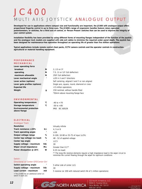
<strong>JC400</strong>MULTI AXIS JOYSTICK ANALOGUE OUTPUTDeveloped for use in applications where compact size and functionality are important, the <strong>JC400</strong> with analogue output offersproportional fingertip control in up to three axes. The <strong>JC400</strong>'s range of ergonomic handles feature rotary operatedpotentiometers, or switches, for a third axis of control, or 'Person Present' switches that can be used to improve the integrity ofyour control system.Installation flexibility has been provided by using different forms of mounting flanges independent of the function of the joystickand the analogue track models are supplied with side exit cables to minimize the required under panel depth. The joystick hasbeen designed for maintenance-free operation throughout an operating life of greater than five million operations.Typical applications include remote control chest packs, CCTV camera controls and the operator controls in construction,agricultural or material handling equipment.PERFORMANCEMECHANICALLever operating forcebreakoutNoperatingNmaximum allowableNLever mechanical angle °Lever action (options)Lever gate profiles (options)Expected lifeWeightg2, 2.5 or 3*7.5, 11 or 12* (full deflection)250* (full deflection)±20 in X and Y directionsSelf centering, aligned X and Y or non alignedSingle axis, square, round, diamond or cross>5 million operations150 nominal, without handle fitted*50mm above mounting flange faceENVIRONMENTALOperating temperature °CStorage temperature °CEnvironmental protectionabove flange-40 to +70-50 to +85IP65 IEC 60529ELECTRICALAnalogue TrackResolutionTrack resistance ±20% kΩTrack operating angle °Output voltage range %Center tap voltage (no load) %Center tap angle °Supply voltage - maximum VdcWiper circuit impedance MΩPower dissipation @ 20°C WSwitch -Directional or Center Off/Center On †Switch operating angle °Supply voltage - maximum VdcLoad current - maximum mA† The <strong>JC400</strong> has an additional center onswitch in each axisVirtually infinite4, 5 or 8±160-100, 10-90 or 25-75 of input (±2%)48 - 52 of applied voltage±2.530Greater than 0.1**0.25 (no load)** The long life resistive elements require a high impedance load in the wiper circuit tominimise the current flowing through the wiper for optimum conditions5 either side of center (±1)305 resistive (or 200 with reduced switch life of 1 million operations)12
DIMENSIONSNote: drawings not to scaleLever forward +Y- orientation mark on base47Rectangular flange(codes B, D & F)Round flange(codes A, C & E)X axis connectionsINSTALLATIONThe joystick is designed to be fittedY axis connectionsfrom below the mounting panel,through a 37mm x 37mm square hole.The effectiveness of the joystick flange57Lever right (+X)sealing is dependent on the panelmounting surface being sufficientlyrigid to compress the sealing gaiter.The surface finish of the mountingø59.84 holes (ø4)on a PCD of 534 holes ø4(or with inserts as order code)Handle connectionsexit herepanel is also critical to achieving anadequate seal and rough surfacefinishes, paint chips, deep scratches,etc. should be avoided.Panelmountingdetails -round flange5337ZC handle shown(See page19 foralternatives)Recommended panel thickness3.5 to 6mmø4375376 maxRecommended screw torqueThe <strong>JC400</strong> joystick has three optionsfor each mounting flange style, whichinclude through holes and threadinserts in the 4mm diameter holes. Tomaintain an effective seal between thejoystick flange and the mounting panel,the mounting screws should beR3Panelmountingdetails -rectangularflangeR3373637455.535398tightened to a suitable torque to matchø4the selected attachment screw size.ELECTRICALCONNECTIONSPVC insulated 7/0.2 (24AWG)flying leads, 240mm longDescriptionY axis forward - positive voltage supplyY axis center tapY axis backward - negative or zero voltage supplyY axis output voltage signalY switch track N/O (lever forward +Y)Y switch track N/O (lever backward -Y)Y switch track center onY switch track commonFlylead colourGreenBrownWhiteBlackPink/BlackGreen/RedRed/BrownYellow/GreenX axis right - positive voltage supplyX axis center tapX axis left - negative or zero voltage supplyX axis output voltage signalX switch track N/O (lever right +X)X switch track N/O (lever left -X)X switch track center onX switch track commonOrangeGreyRedYellowOrange/BlackRed/BlackOrange/RedPurple/RedSee over ☛for ordering information13
<strong>JC400</strong>ANALOGUE OUTPUTHOW TO SPECIFYPERFORMANCE OPTIONS FEATURE CODEMOUNTING FLANGE Round flange, 59.8mm diameter with 4 x 4mm through holesARectangular flange, 47 x 57mm with 4 x 4mm through holesBRound, as code A, but with Metric thread inserts (M3 x 0.5p)CRectangular, as code B, but with Metric thread inserts (M3 x 0.5p)DRound, as code A, but with Unified thread inserts (4-40 UNC x 0.025)ERectangular, as code B, but with Unified thread inserts (4-40 UNC x 0.025)FAXESSingle axis with analogue trackDual axisYXYTRACKSAnalogue potentiometer, 4k, 0-100%, ±5° directional switchAnalogue potentiometer, 5k, 10-90%, ±5° directional switchAnalogue potentiometer, 8k, 25-75%, ±5° directional switchNNRRQQDETENTSNot available with analogue tracks -/-LEVER SPRING FORCELight duty, 2N breakout, 7.5N full deflectionMedium duty, 2.5N breakout, 11N full deflectionHeavy duty, 3N breakout, 12N full deflectionLAMAHAHANDLE STYLESSee page 18Standard handle, no functionsStandard handle with momentary push buttonStandard handle with momentary switch actionRotary Z axis handle with analogue track and directional switchRotary Z axis handle with end of travel switches onlyFinger grip handle with momentary top button switchFinger grip handle with two momentary side button switchesFinger grip handle with two momentary side and top button switchesZCZC1ZCSZA or ZA2ZASSW1SW2SW3GATE(lever movement limiter)SquareRoundDiamondCross - only suitable for use with non-switched handles (ZC)SRDCSEATAligned with axisNon-alignedPNEXAMPLE ORDER CODE<strong>JC400</strong>-A-XY-NN-/-MA-ZA-S-P14
<strong>JC400</strong>safe control forhydraulic equipmentMULTI AXIS JOYSTICK DIGITAL OUTPUTDeveloped for use in applications where compact size and functionality are important, the <strong>JC400</strong> with Digital Output optionoffers fingertip control in one or two axes, with a choice of handles for a third axis of control. The <strong>JC400</strong>'s range of ergonomichandles feature rotary operated potentiometers, or switches, or 'Person Present' switches that can be used to improve theintegrity of your control system.The Digital track option includes a detent mechanism that provides three sequential positions either side ot the center position.The detent positions align with the switch outputs in true X and Y directions only.Installation flexibility has been provided by using different forms of mounting flanges independent of the function of thejoystick, and the digital output joysticks are fitted with standard electronic connectors to minimize installation time. The joystickhas been designed for maintenance-free operation throughout an operating life of greater than five million operations.Typical applications include remote control chest packs, CCTV camera controls and the operator controls in construction,agricultural or material handling equipment.PERFORMANCEMECHANICALLever operating forcebreakoutNoperatingNmaximum allowableNLever mechanical angle °Lever action (options)Lever gate profiles (options)Expected lifeWeightg3, 4 or 6*12, 13.5 or 18* (full deflection)250* (full deflection)±20 in X and Y directionsSelf centering, aligned X and Y or non alignedSingle axis, square, round, diamond or cross.>5 million operations150 nominal, without handle fitted*50mm above mounting flange faceENVIRONMENTALOperating temperature °CStorage temperature °CEnvironmental protectionabove flange-40 to +70-50 to +85IP65 IEC 60529ELECTRICALNumber of switch positionsNumber of detentsSwitch/detent angles °Supply voltage - maximum VdcLoad current - maximum mA3 either side of center3 either side of center±6.6, ±13.3, ±2030100 resistive @25°CTRUTH TABLETruth table for digital switch track outputY and X axis signals are NormallyOpen (0) at lever center position. Switchsequences close (1) depending ondirection of lever movement and detentposition.Detent SwitchPosition Output1 2 3 Right Left(or Forward) (or Backward)3 1 1 1 1 02 1 1 0 1 01 1 0 0 1 00 0 0 0 0 0-1 1 0 0 0 1-2 1 1 0 0 1-3 1 1 1 0 115
DIMENSIONSNote: drawings not to scaleLever forward +Y- orientation mark on baseINSTALLATIONRound flange(codes A, C & E)47Rectangular flange(codes B, D & F)The joystick is designed to be fitted frombelow the mounting panel, through a37mm x 37mm square hole. Theeffectiveness of the joystick flange sealing is57Lever right (+X)dependent on the panel mounting surfacebeing sufficiently rigid to compress theø59.8sealing gaiter. The surface finish of themounting panel is also critical to achieving4 holes (ø4)on a PCD of 534 holes (ø4)(or with inserts as order code)an adequate seal and rough surfacefinishes, paint chips, deep scratches, etc.should be avoided.Recommended panel thickness3.5 to 6mmPanelmountingdetails -round flange5337375376 maxZC handle shown(see page 19 foralternatives)ø4Recommended screw torqueThe <strong>JC400</strong> joystick has three options forR3each mounting flange style, which includethrough holes and thread inserts in the4mm diameter holes. To maintain aneffective seal between the joystick flangeand the mounting panel, the mountingPanelmountingdetails -rectangularflange373637455.5358screws should be tightened to a suitabletorque to match the selected attachmentscrew size.R3ø4839Pin 8Pin 16ELECTRICAL CONNECTIONSConnectionMating connector and pins kit(order separately)FCI DUBOX TM 2 x 8 way male connector (76385-308)SA47363 (contains DUBOX TM 65239-008, 65239-002 and 65239-003 femaleconnectors and pins 76357-301 suitable for AWG 22-30 wire size)Requires crimping pliers (FCI No. HT234) to fit pins to wires.DescriptionConnector Pin NumberY axis switch 1 3Y axis switch 2 14Y axis switch 3 16Y axis signal N/O (lever forward +Y) 9Y axis signal N/O (lever backward -Y) 1Y axis switch track common 5X axis switch 1 4X axis switch 2 7X axis switch 3 10X axis signal N/O (lever right +X) 2X axis signal N/O (lever left -X) 6X axis switch track common 516
<strong>JC400</strong>DIGITAL OUTPUTHOW TO SPECIFYPERFORMANCE OPTIONS FEATURES CODEMOUNTING FLANGERound flange, 59.8mm diameter with 4 x 4mm through holesARectangular flange, 47 x 57mm with 4 x 4mm through holesBRound, as code A, but with Metric thread inserts (M3 x 0.5p)CRectangular, as code B, but with Metric thread inserts (M3 x 0.5p)DRound, as code A, but with Unified thread inserts (4-40 UNC x 0.025)ERectangular, as code B, but with Unified thread inserts (4-40 UNC x 0.025)FAXESSingle axis with digital trackDual axisXXYTRACKSDigital - 3 switches either side of centerDDDETENTSOnly available with digital tracksDLEVER SPRING FORCELight duty, 3N breakout, 12N full deflectionMedium duty, 4N breakout, 13.5N full deflectionHeavy duty, 6N breakout, 18N full deflectionLDMDHDHANDLE STYLESSee page 18Standard handle, no functionsStandard handle with momentary switch actionRotary Z axis handle with analogue track and directional switchRotary Z axis handle with end of travel switches onlyZCZCSZA or ZA2ZASGATE(lever movement limiter)SquareRoundDiamondCross - only suitable for use with non-switched handles (ZC)SRDCSEATAligned with axisNon-alignedPNEXAMPLE ORDER CODE<strong>JC400</strong>-B-XY-DD-D-MD-ZC-R-N17
<strong>JC400</strong>MULTI AXIS JOYSTICKHANDLE OPTIONSZAThe ZA and ZAS handles are designedto give an additional axis ofproportional or switched control, usingfingertip action to rotate the handle.The handles have a self-centering actionwhen released, and rotate about theircenter, giving either analogue output withswitched reference signals (ZA or ZA2) orend of travel switching only (ZAS).ZCThe convex top profile of the ZC handleallows for simple thumb control of the <strong>JC400</strong>range. 'Person present' switch functions canbe incorporated by using the ZC1 externalbutton switch or the ZCS internal switch toverify the change in signals from thejoystick, which may help to increase theintegrity of your control system.SWThe cylindrical profile of the SW handle allowsfull grip use when controlling the <strong>JC400</strong> range.'Person present' switch functions can beincorporated by using a choice of three switcharrays which can offer a combination of finger andthumb activation. The external button switches canbe used to verify the change in signals from thejoystick, which may help to increase the integrity ofyour control system, or enable control of additionalfunctions.18
ZA HANDLE OPTIONPERFORMANCEMax height above flange mmMaximum diametermmOperating temperature °CEnvironmental sealing (IEC 60529)Z AXIS MECHANICALHandle rotational torquebreakoutNmoperatingNmmaximum allowable NmHandle mechanical angle °Handle actionExpected lifeZ AXIS ELECTRICALAnalogue track (ZA and ZA2 only)ResolutionTrack resistance ±20% kΩTrack operating angle °Output voltage range %Center tap voltage (no load) %Z AXIS ELECTRICALDirectional or Centre SwitchSwitch operating angle °Supply voltage - maximum VdcLoad current - maximum mAZA, ZA2ZAS80 8039 39-25 to +50 -25 to +50IP65IP650.10.15 to 0.251±29 to ±30Self centering1 million operationsVirtually infinite3.1 or 5.4 (ZA2)±277-93 or 25-75 (ZA2) of input47 - 53 of applied voltageCenter tap angleSupply voltage - maximumWiper circuit impedance°VdcMΩ±2.530> 0.1**** The long life resistive elements require Power a high dissipation impedance @ load 20°C in the wiper W circuit 0.25(no to load)minimise the current flowing through the wiper for optimum conditionsZA, ZA2ZAS4 either side of center (±1) 20 either side of center (±2)30 302 (resistive) 2 (resistive)DIMENSIONSNote: drawings not to scale80 max29.5 maxø38.5 maxCW+ZInstallation noteThe protective rubber cap must beremoved before fitting the joystickthrough the mounting hole.Re-fit the rubber cap aftermounting in the panel.ELECTRICAL CONNECTIONSLeads exit from the underside of the mounting flange. PVC insulated 7/0.2 (24AWG) flying leads, 240mm longDescriptionFlylead colourZAZASZ axis positive voltage supply Yellow/Red -Z axis center tap Blue -Z axis negative or zero voltage supply Violet -Z axis output voltage signal Pink -Z switch track N/O (handle CW +Z) Yellow/Black Yellow/BlackZ switch track N/O (handle CCW -Z) White/Red White/RedZ switch track common Red/Blue Red/Blue19
ZC HANDLE OPTIONPERFORMANCEMax height above flange mmMaximum diametermmEnvironmental sealing (IEC 60529)Number of switchesActionSwitch operating forceNMaximum currentmAExpected life (operations)ZC ZC1 ZCS76 76 7623 23 23IP65 IP65 IP650 1 1- Momentary button Momentary handle depress- 3 7- 200 @ 50Vdc 100 @ 30Vdc- 1 million 500,000DIMENSIONSNote: drawings not to scaleZC ZC1 Button colour - Red ZCSPresstoactivateswitch76 max76 max76 maxELECTRICAL CONNECTIONSLeads exit from the underside of the mounting flange. PVC insulated 7/0.2 (24AWG) flying leads, 240mm longDescriptionCommon terminalN/O contact switch 1ZC1/ZCS Flylead colourRed/GreenWhite/Black20
SW HANDLE OPTIONPERFORMANCEMax height above flange mmMaximum diametermmEnvironmental sealing (IEC 60529)Number of switchesActionSwitch operating forceNMaximum current @ 50Vdc mAExpected life (operations)SW1 SW2 SW3120 112 12028 28 28IP65 IP65 IP651 2 3Momentary button32001 millionDIMENSIONSNote: drawings not to scaleSwitch 1SW1 SW2 SW3Switch 1Switch 2Switch 2Switch 3Switch 3120112All buttons - colour redELECTRICAL CONNECTIONSLeads exit from the underside of the mounting flange. PVC insulated 7/0.2 (24AWG) flying leads, 240mm longDescriptionFlylead colourSW1 SW2 SW3Common terminal Black Black BlackN/O contact switch 1 White - WhiteN/O contact switch 2 - Pink PinkN/O contact switch 3 - Yellow YellowThis handle option is not available with <strong>JC400</strong> Digital Output21