Experimental Investigation of Electric Drive Dynamics
Experimental Investigation of Electric Drive Dynamics
Experimental Investigation of Electric Drive Dynamics

Create successful ePaper yourself
Turn your PDF publications into a flip-book with our unique Google optimized e-Paper software.
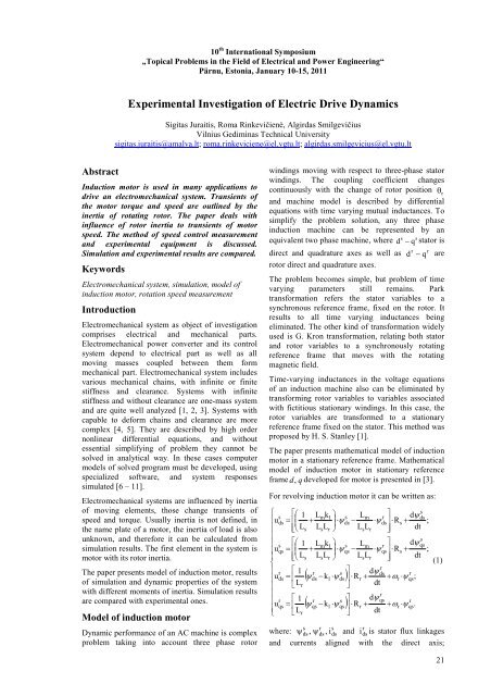
10 th International Symposium„Topical Problems in the Field <strong>of</strong> <strong>Electric</strong>al and Power Engineering“Pärnu, Estonia, January 10-15, 2011<strong>Experimental</strong> <strong>Investigation</strong> <strong>of</strong> <strong>Electric</strong> <strong>Drive</strong> <strong>Dynamics</strong>Sigitas Juraitis, Roma Rinkevičien÷, Algirdas SmilgevičiusVilnius Gediminas Technical Universitysigitas.juraitis@amalva.lt; roma.rinkeviciene@el.vgtu.lt; algirdas.smilgevicius@el.vgtu.ltAbstractInduction motor is used in many applications todrive an electromechanical system. Transients <strong>of</strong>the motor torque and speed are outlined by theinertia <strong>of</strong> rotating rotor. The paper deals withinfluence <strong>of</strong> rotor inertia to transients <strong>of</strong> motorspeed. The method <strong>of</strong> speed control measurementand experimental equipment is discussed.Simulation and experimental results are compared.KeywordsElectromechanical system, simulation, model <strong>of</strong>induction motor, rotation speed measurementIntroductionElectromechanical system as object <strong>of</strong> investigationcomprises electrical and mechanical parts.Electromechanical power converter and its controlsystem depend to electrical part as well as allmoving masses coupled between them formmechanical part. Electromechanical system includesvarious mechanical chains, with infinite or finitestiffness and clearance. Systems with infinitestiffness and without clearance are one-mass systemand are quite well analyzed [1, 2, 3]. Systems withcapable to deform chains and clearance are morecomplex [4, 5]. They are described by high ordernonlinear differential equations, and withoutessential simplifying <strong>of</strong> problem they cannot besolved in analytical way. In these cases computermodels <strong>of</strong> solved program must be developed, usingspecialized s<strong>of</strong>tware, and system responsessimulated [6 – 11].Electromechanical systems are influenced by inertia<strong>of</strong> moving elements, those change transients <strong>of</strong>speed and torque. Usually inertia is not defined, inthe name plate <strong>of</strong> a motor, the inertia <strong>of</strong> load is alsounknown, and therefore it can be calculated fromsimulation results. The first element in the system ismotor with its rotor inertia.The paper presents model <strong>of</strong> induction motor, results<strong>of</strong> simulation and dynamic properties <strong>of</strong> the systemwith different moments <strong>of</strong> inertia. Simulation resultsare compared with experimental ones.Model <strong>of</strong> induction motorDynamic performance <strong>of</strong> an AC machine is complexproblem taking into account three phase rotorwindings moving with respect to three-phase statorwindings. The coupling coefficient changescontinuously with the change <strong>of</strong> rotor position θ rand machine model is described by differentialequations with time varying mutual inductances. Tosimplify the problem solution, any three phaseinduction machine can be represented by ans sequivalent two phase machine, where d − q stator isdirect and quadrature axes as well asrotor direct and quadrature axes.r rd − q areThe problem becomes simple, but problem <strong>of</strong> timevarying parameters still remains. Parktransformation refers the stator variables to asynchronous reference frame, fixed on the rotor. Itresults to all time varying inductances beingeliminated. The other kind <strong>of</strong> transformation widelyused is G. Kron transformation, relating both statorand rotor variables to a synchronously rotatingreference frame that moves with the rotatingmagnetic field.Time-varying inductances in the voltage equations<strong>of</strong> an induction machine also can be eliminated bytransforming rotor variables to variables associatedwith fictitious stationary windings. In this case, therotor variables are transformed to a stationaryreference frame fixed on the stator. This method wasproposed by H. S. Stanley [1].The paper presents mathematical model <strong>of</strong> inductionmotor in a stationary reference frame. Mathematicalmodel <strong>of</strong> induction motor in stationary referenceframe d, q developed for motor is presented in [3].For revolving induction motor it can be written as:⎧⎪u⎪⎪⎪⎪u⎨⎪⎪u⎪⎪⎪u⎪⎩sdssqsrdsrqs⎡⎛= ⎢⎜⎢⎣⎝⎡⎛= ⎢⎜⎢⎣⎝⎡= ⎢⎣⎡= ⎢⎣1L1L1Lr1LrssLmk+L LLmk+L L⎞s⎟⋅ψ⎠r s( ψ − k ⋅ψ)dsr s( ψ − k ⋅ψ)sqsrss1r1r11qsdsLm−L L⎤⎥⋅R⎦rsrdψ+dt⎤r⋅ψds⎥⋅R⎥⎦rqsdψds+ ;dt⎞⎤s L rdψ⎟mqs⋅ψqs − ⋅ψqs⎥⋅Rs+ ;⎠ LsLr⎥⎦dt(1)r⎤ dψds rds ⎥⋅Rr+ + ωr⋅ψqs;⎦ dtsrqs+ ω ⋅ψ.where: ψ ds , ψds, idsand idsis stator flux linkagesand currents aligned with the direct axis;rrsss21
Results <strong>of</strong> simulation are presented in Fig. 2. Thesettling time increases with increasing <strong>of</strong> rotorinertia. At small inertia, the speed exceeds rated thatand has oscillating character.Rotation speed, rad/s180160140120100806040201 2 3 4 500 0.5 1 1.5 2Time, sFig. 2. Motor speed response at different inertiamoment:1 – inertia is 0,005 kg·m 2 ;2 – inertia is 0,05 kg·m 2 ;3 – inertia is 0,1 kg·m 2 ;4 – inertia is 0,125 kg·m 2 ;5 – inertia is 0,15 kg·m 2 .<strong>Experimental</strong> speed measuring device<strong>Experimental</strong> model is elaborated for 2.2 kWinduction motor, whose parameters are presented inTable 1. Torque was measured by torque sensor <strong>of</strong>“Lorenz Messtechnik” company, whose parametersare given in Table 2. Both elements were coupled bydouble-jointed coupling.Table 2. Specification <strong>of</strong> torque sensorTypeDR-2212Accuracy class % 0,1Repeatability (DIN 1319) % ±0,02Excitation voltage V DC 12...28Output signal mA 0 - ±5 VNominal temperature range °C +5 - +45Measuring range N·m 20Angle control 360 impulses,2 traces, 90° displacedAngle impulses output signal V DC 0 - ±10General view <strong>of</strong> experimental model is presented inFig. 3Fig. 3. <strong>Experimental</strong> model <strong>of</strong> induction motor andtorque sensorFor speed measurement one <strong>of</strong> torque measuringdevice TTL signals, giving information about rotorangle position, is used. Let in will be A signal.Repeating pulses can be expressed as function <strong>of</strong>input signals frequency. For speed measurement theconverter changing frequency to direct currentvoltage, should be applied. For this purpose specialmicrochip LM2907N is used. All measuring circuitelements were calculated. According to synchronousspeed <strong>of</strong> motor and number <strong>of</strong> pulses per revolution,the frequency <strong>of</strong> pulses at synchronous speed iscalculated as:n 1500fes = ⋅ nA= ⋅ 360 = 9000 Hz ,(9)60 60where:f s is frequency <strong>of</strong> pulses at synchronous speed;n e is speed <strong>of</strong> rotor, rpm;n a is number <strong>of</strong> pulses per revolution in the channelA.The greatest dimensional frequency is calculated as:f = 1,5 ⋅ fs = 1,5 ⋅9000= 13500Hz;(10)maxwhere: f max is maximal dimensional frequency <strong>of</strong>converter.Converter is elaborated according to the circuit,shown in Fig. 4.Fig. 4. <strong>Electric</strong>al circuit <strong>of</strong> the converterElements R 3 and C 3 comprise the filter <strong>of</strong> outputsignal. Resistance R 4 and R 5 are used to set upvoltage value at which the input pulse is identified.Microchip is matched for required frequency bychoosing capacitor C 1 and resistance R 1 . Accordingto recommendations, the capacitance value is chosenC 1 =0,1nF. At this capacitance resistance R 1 iscalculated as:1 1R1 = = = 740 kΩ.f 10max ⋅C −1 13500 ⋅1⋅10(11)Designed converter was tested. For this purposeinput pulses were generated by standard signalgenerator with variable frequency; the amplitude <strong>of</strong>23