HYDROVEX® FluidSep Vortex Separator - Veolia Water Solutions ...
HYDROVEX® FluidSep Vortex Separator - Veolia Water Solutions ...
HYDROVEX® FluidSep Vortex Separator - Veolia Water Solutions ...

You also want an ePaper? Increase the reach of your titles
YUMPU automatically turns print PDFs into web optimized ePapers that Google loves.
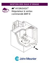
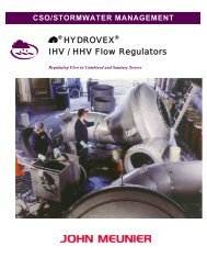
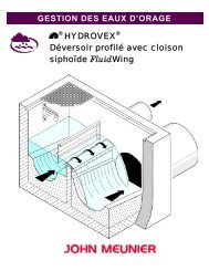
CSO/STORMWATER MANAGEMENT®HYDROVEX ®<strong>FluidSep</strong> <strong>Vortex</strong> <strong>Separator</strong>
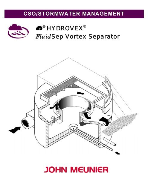
HYDROVEX ® FLUIDSEP VORTEX SEPARATORINTRODUCTIONThe HYDROVEX ® <strong>FluidSep</strong> <strong>Vortex</strong> <strong>Separator</strong> is a tool in the treatment of CSO and Stormwater. The treatment relies on theproperties of the controlled vortex to eliminate settleable suspended solids, as well as floatables carried by the incoming water.Since 1985, UFT, the German leader in CSO and Stormwater equipment development, has developed the HYDROVEX ® <strong>FluidSep</strong>.UFT and its owner, Dr. Hans Brombach, have specialized since the late ‘70s in induced vortex equipment design. Following the variouslaboratory and field developments, UFT has created a new concept of vortex separator, the HYDROVEX ® <strong>FluidSep</strong> that presents betterperformances than those already existing.UFT started the first HYDROVEX ® Fluid Sep units in the summer of 1987 in the City of Tengen near Schaffhausen in Germany. Theunits are still operating successfully. A special research program that ended in the summer of 1990 supplied evidence of the superiorefficiency of the HYDROVEX ® <strong>FluidSep</strong>. The program was based on the qualitative evaluation of sampling campaigns performed atthe installation.HYDROVEX ® <strong>FluidSep</strong> is currently in full operation in Germany, France and the United States of America.GENERALITIESRegulators and retention tanks are the most common CSO pollution control structures. If the combined sewer regulator allowsimportant flows to pass without treatment to the outfall, the retention tank acts differently: it offers the advantage of storing thepolluted water. In the case of transit type tanks, it can clarify the water before discharging it. The drawback is that these tanks arealways very expensive and represent a massive capital investment.For storm drainage, the stormwater is evacuated by the shortest path directly to the receiving body of water without any treatment.Under these conditions, important pollutant quantities, resulting from the washing of the impervious surfaces (mainly streets,parking lots and roof drainage) are directly sent to the environment.The HYDROVEX ® <strong>FluidSep</strong> <strong>Vortex</strong> <strong>Separator</strong> offers, both in Combined Sewers and in Stormwater Drainage, an effective solutionto protect the receiving bodies of water. The technology is particularly interesting when applied in combined sewer rehabilitation orextension. The <strong>Vortex</strong> <strong>Separator</strong> is also very effective as a stormwater treatment.OPERATIONThe operation of the HYDROVEX ® <strong>FluidSep</strong> <strong>Vortex</strong> <strong>Separator</strong> described here is based on an In-line installation in a CombinedSewer System. The Dry Weather Flow that gets to the unit passes by freely on the sloped bottom towards the central cone ofevacuation and then through a flow regulator.During a storm event, the incoming flow becomes bigger than the regulated outflow. This will effectively start the filling of thevortex separator. A lot of minor events can be fully intercepted and contained inside the vortex separator volume without actualoverflow.For more intense or more durable storm events, the HYDROVEX ® <strong>FluidSep</strong> <strong>Vortex</strong> <strong>Separator</strong> start overflowing through its centralannular overflow weir. This weir is made of two plunging cylindrical treatment baffles providing a double crown arrangement.The overflow water is evacuated through the ring-shaped opening formed by these two treatment baffles. The overflow is fixed inthe circular opening of the top cover of the vortex separator structure. The overflowed water falls from the weir on the upperchamber of the separator and is then evacuated, either towards an additional treatment system or directly to the outfall. Due to itstangential inlet port, the incoming water brings the mass of retained water into a rotational movement inside the tank.This rotational movement induces the ideal conditions for the creation of a vortex separation in the tank.The resulting flow pattern is non-turbulent and very favorable to the separation of suspended solids. These particles can readilysettle and are furthermore pulled by the centrifugal currents towards the wall of the separator. Once the particles are caught on thelimit layer along the walls, they fall to the structure bottom and are finally brought to the unit’s evacuation cone. From there, theyare carried out with the underflow water through the regulator. The double crown baffle arrangement, plunging into the centralsection of the chamber, helps to ease secondary currents and increase the limit surface area. The overflow water is clarified.
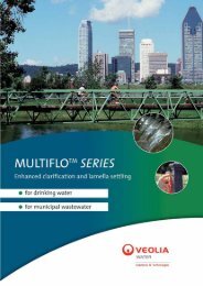
When the <strong>HYDROVEX®</strong> <strong>FluidSep</strong> <strong>Vortex</strong> <strong>Separator</strong> is filled, an air pocket is formed under the unit’s cover, imprisoned by thebaffle partition arrangement. The floatables entering the separator will be caught there and will simply circulate around until the unitprogressively gets back to dry time flow conditions. The lower surface of the cover always remains free of water, due to the capturedair pocket.If the flow conditions allow it, the vortex separator lower cone can be fitted with an underflow drain. This drain can help separate thecoarse elements from the separator. It can also help flush out entrapped material. The opening of the drain allows the draining of thecone to a stocking area located below the device. The sludge drained from the unit must be removed periodically after naturaldehydration.Bench Test for HYDROVEX ® <strong>FluidSep</strong><strong>Vortex</strong> <strong>Separator</strong>Adjustable weirFlow equalizerCoverAir PocketCircular baffleOverflow tooutfall<strong>Vortex</strong>chamberElectronicmonitoringRaw waterFlow regulatorInletSupportsUnderflow conePurgeactuatorUnderflow pipePurge valveSludge pitScreenOutlet to WWTPFigure 1: Cross section of a Hydrovex ® <strong>FluidSep</strong> <strong>Vortex</strong> <strong>Separator</strong> in full operation
APPLICATIONSThe HYDROVEX ® <strong>FluidSep</strong> <strong>Vortex</strong> <strong>Separator</strong> has numerous possible applications, either in the storm drainage lines, in thecombined sewer system or at the wastewater treatment plant. If required, many HYDROVEX ® <strong>FluidSep</strong> units can be operated inparallel. Also, the HYDROVEX ® <strong>FluidSep</strong> can be implanted off-line from the main sewer system. In the case of poor flowconditions, the HYDROVEX ® <strong>FluidSep</strong> can even be pump fed.IndependantTreatment chainIn-line operationOff-line operationFigure 2: Various configurations of HYDROVEX ® <strong>FluidSep</strong> vortex separatorsCOMBINED SEWER APPLICATIONThe HYDROVEX ® <strong>FluidSep</strong> <strong>Vortex</strong> <strong>Separator</strong> can be used as a main CSO treatment, in replacement of a conventional overflowweir arrangement. The overflow frequency will be automatically reduced, simply based on the important retention volume offeredby the vortex separator’s structure. In overflow conditions, the unit will offer a treatment level equivalent to a headwork. Animportant fraction of the suspended solids and floatables will be retained and sent to the Wastewater Treatment Plant.The use of the HYDROVEX ® <strong>FluidSep</strong> <strong>Vortex</strong> <strong>Separator</strong>, in combination with a transit type clarifier tank, is very effective. Thevortex separator will be used as a preliminary treatment whereas the transit type clarifier tank will operate both as a retention tankand a polishing treatment. Low intensity events will be accounted for by the vortex separator alone. For bigger events, the overflowwater, already treated in the vortex unit, will receive up to primary clarifier degree treatment in the transit type clarifier tank. Bothunits are performing far better together than in their stand-alone version. The problems related to resuspending settled materialsand cleaning of the retention/treatment structure is greatly reduced.
STORMWATER APPLICATIONThe HYDROVEX ® <strong>FluidSep</strong> <strong>Vortex</strong> <strong>Separator</strong> can treat stormwater from street, roads, parking lots, roof drains, truck loadingpads and industrial parks. The bigger part of settleable suspended solids can be trapped inside the unit rather than being freely sentto the environment. However, only an in-line arrangement can be used for this type of application. In storm drains, the solid loadessentially includes mineral elements. These can either be sent to the sanitary sewer line or pumped out into a grit classifier foreventual disposal. This last solution is particularly adapted to areas where there are conditions with high grit, sand and salt content.WASTEWATER TREATMENT PLANT APPLICATIONThe Hydrovex ® <strong>FluidSep</strong> <strong>Vortex</strong> <strong>Separator</strong> can be installed in the Wastewater treatment plant as an additional headworkcomponent. It allows extra polishing of the grit chamber outflow.DIMENSIONINGThe fundamental data required to select and size a HYDROVEX ® <strong>FluidSep</strong> <strong>Vortex</strong> <strong>Separator</strong> is the local hydraulic conditions andpeak flow value Q max . With these limit conditions, we can determine the size and the hydraulic efficiency of the separator.The HYDROVEX ® <strong>FluidSep</strong> should never be too small to maintain the retention volume function of the structure. Conversely,oversizing the unit will increase the construction expenses uselessly. If necessary, it is possible to design several vortex separatorsin parallel.To determine the efficiency of the HYDROVEX ® <strong>FluidSep</strong> <strong>Vortex</strong> <strong>Separator</strong>, it is recommended that a formal characterizationcampaign be carried out. This will help to identify the real characteristics of the effluent by identifying the composition of pollutingmaterials to separate. When such data is not available, we can use the numerous sedimentation curves available in our group.The additional equipment necessary to properly operate a HYDROVEX ® <strong>FluidSep</strong> <strong>Vortex</strong> <strong>Separator</strong> is variable. Normally, it islimited to a flow regulator installed at the underflow exit of the structure. We recommend the installation of flow and levelmonitoring devices to insure the follow up of the unit and the frequency of activation of the structure.Emergency overflow <strong>Vortex</strong> separator Regulator chamberh 1hh ZUh1 h 3Q B ÜH AQ WAQ Z uh 4h 5d ZU h 7h 6h 8h 9Q TQ ABFigure 3: Side section of a simple vortex separator installation. In-line arrangements with free flow conditions.John Meunier Inc.ISO 9001 : 2000Head OfficeOntario Office4105 Sartelon2000 Argentia Road, Plaza 4, Unit 430Saint-Laurent (Quebec) Canada H4S 2B3 Mississauga (Ontario) Canada L5N 1W1Tel.: 514-334-7230 www.johnmeunier.com Tel.: 905-286-4846 www.johnmeunier.comFax: 514-334-5070 cso@johnmeunier.com Fax: 905-286-0488 ontario@johnmeunier.comUSA Office2209 Menlo AvenueGlenside, PA USA 19038Tel.: 412- 417-6614 www.johnmeunier.comFax: 215-885-4741 asteele@johnmeunier.comRevised : 2008-10-01