The Memristor: ANew Bond Graph Element - CiteSeerX
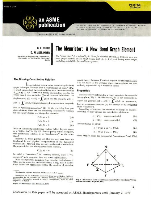
The Memristor: ANew Bond Graph Element - CiteSeerX
The Memristor: ANew Bond Graph Element - CiteSeerX

You also want an ePaper? Increase the reach of your titles
YUMPU automatically turns print PDFs into web optimized ePapers that Google loves.
Paper No.n-Aut·NJ<strong>The</strong> Society shall not be responsible for statements or opinions:
SPRIIIG 1)...TAPEIlED "",,",0.--.F-----... p: Sedt(8) System Sehanat1cVELOClTY SOURCE1J171J1I1Flg.2<strong>Memristor</strong> constitutive relation(mass) C --t1t-E (velOCity source)1/0........(epring) I M (memr1stor)(b)<strong>Bond</strong> <strong>Graph</strong>, with memr1stor~(t.)R1r--- lI'---\l:CRJ.le: TF'1F(t.)t--lt--V=C(e)C----t1""""-E1olor ~TF (modlllated resistor)r or .... _,,, ~R<strong>Bond</strong> <strong>Graph</strong>, with modulated resistorFig. 4 Schematic and bond graph of mechanical system with displacement-modulateddashpot,:,.1 l::t:'I! .~a!:lJri~:.~ t~~ ~~=-:r-i!:tor~ r.:-::~.~t1t.u· iv...r'''~ 1 ::J t. ~ ...,!; •: (.::q.l;,."":J.':Fig. 3 //I.~ ~ ,;1(;;'(1) .,. (AK(. :)nFig. 5Memductance curvesthe incremental l'memduct.ance." We see that, dynamically,the memristor appears as eit.her an impulse or a charge modulatedresistor. Notice that for the special case of a linear constitutiverelation, III = constant and W = constant., a memrbitor appearsa.c; an ordinary resist{)r. So memristors have meaning only fornonlinear systems (which may account in part for their neglect.till now). Furthermore, a glance rot. the dtetrahedron of state"Fig. 1, shows th,at, since both an integration and a differentiationare involved in vie~ring the memristor as a "resistor" (Le., ont.he e-fplane), the memristor, like the resistor, is causally neutral.That is, it may accept either an effort or a How as input. variable.However, there appear to be some restrictions insofar as devicemodeling is concerned which will be mentioned in the following.Since the memristor is a I-port device, it is trivially reciprocalin (q-p) coordinates. However, it is obvious that :l.ll definitionsmay be easily extended to the case of multiport, nonreciprocalresistors [31.What then distinguishes a memristor from a resistor? Consider,for example, the tapered dashpot shown in Fig. 3. If weatt.empt to characterize this device on the e-f plane, mistakingit. for a true resist{)r, we would not obtain a unique con..
SOlAllror.l' = ::: /
1·e~_---Fig.8Memristance curvespthat the electrical resistance is inversely proportional to theconcentration in the intermembrane space one obtains anexponential memrist,ance curve, as shown by the dashed linein Fig. 8. <strong>The</strong> linear memristance shown by the solid line yieldsa completely linear system (Le., constant resistance) for comparisonpurposes.<strong>The</strong> results on the state plane projection are shown in Fig, 9for sinusoidal excitation. As expected, the linear memristance(solid line) has an elliptical trajectory indicating the absenceof any harmonic..'i. <strong>The</strong> nonlinear case shows behavior indicativeof an output containing more than just the forcing frequencyand, because of the asymmetric constitutive relation of thememristor, its trajectory is also asymmetric.<strong>The</strong>re are two apparent restrictions on the use of the memristoras a modeling device. (i) According to equation (4), thememristol', viewed on the e-f plane, models a linear displacementmodulatedresistor. That is, the device appears nonlinear byvirtue of the nonlinear p-q relationship; but the f = fee, q)surface representing the resistor characteristic can only be aruled surface, i.e., a surface swept out by a straight line. (ii)<strong>Memristor</strong>s whose constitutive relation becomes horizontal (q =constant) are vertical (p = constant) are usually not admissiblemodels, since the device continues to integrate the effort eventhough displacement is static. <strong>The</strong>refore, when polarity isreversed across the device, a hysteretic behavior may occur inp-q as well as e-f coordinates.Fig.9ReferencesState-plane trajectories for sinusoidal excitation1 Paynter, H. M., Analysis and Design of EngineeringSystems, <strong>The</strong> MIT Press, Cambridge, Mass., 1961.2 Shearer, J. L., :Murphy, A. T., and R.ichardson, H. H.,Introduction to Systems Dynamics, Addison-Wesley, Reading,Mass., 1967.3 Chua, L., il<strong>Memristor</strong>-<strong>The</strong> Missing Circuit <strong>Element</strong>,"IEEE Transactions on Circuit <strong>The</strong>ory, Sept. 1971.4 Purcell, E. M., Electricity and .Jlagnetism, <strong>The</strong> BerkeleyPhysics Course, Vol. II, McGraw-Hill, New York, 1966.5 Oster, G., and Auslander, D" "Topological Representationsof <strong>The</strong>lmodynamic Systems," Journal of the Franklin Institute,Parts I, II, 1971.Printed in U.B.A.4Transactions of the ASME
NEWS & VIEWSNATURE|Vol 453|1 May 2008songs worked like a charm. So it seems thatthe male forms of fru fine-tune these neuronsin the male to perfect his song.Even if it is not well tuned, a song circuit ispresent in females. So what makes them hidetheir singing talent? <strong>The</strong> selective activation ofthoracic song circuits in males but not femalesis likely to be controlled by some subset of thefru neurons in the brain. Indeed, classic studiesof gynandromorph flies (which have a mixtureof male and female nervous tissues) indicated 4that certain brain regions must be ‘male’ to triggerthe song. In this context, it is interesting tonote that several pairs of neurons descendingfrom the brain to the thorax are fru-positive 1 .<strong>The</strong>se neurons are prime candidates to conveysex-specific commands to the thoracic songcircuits.<strong>The</strong> picture that emerges from these studiesis that the circuitry for song generation, likethat for pheromone processing 9,10 , is largelyshared between the sexes. <strong>The</strong> crucial sex differencesseem to lie somewhere in betweenthese bisexual input and output circuits, indimorphic ‘decision-making’ centres in thebrain. A similar design has recently been proposed11 for the circuits that regulate sexualbehaviour in mice: in females unable to perceivecertain olfactory cues, male-like sexualbehaviour results, presumably reflecting theactivation of otherwise dormant circuits forthese male behaviours in females. This modularand bisexual design affords considerableflexibility, which may even be exploited withinthe animal’s own lifetime. Some species of fish,for example, change their sexual behaviour inresponse to social cues 12 . <strong>The</strong>y may do thisby simply resetting a few critical switches inthe decision-making centres of an otherwisebisexual nervous system.<strong>The</strong>re is great excitement in neurosciencethese days, as genetic tools are used to anatomicallyand functionally dissect the neural circuitsthat mediate complex animal behaviours 13 .Clyne and Miesenböck’s work 1 beautifullyillustrates the essential role photoactivationmethods will have in this endeavour. As biochemistsand biophysicists have long appreciated,surprising insights come when one canaddress questions of causality as well as correlation,reducing a system to its essentials andpushing it beyond its normal operating range.<strong>The</strong> mating behaviours of the humble fruitflyseem to be particularly amenable to this typeof reductionist approach.■Jai Y. Yu and Barry J. Dickson are at the ResearchInstitute of Molecular Pathology, Dr.-Bohr-Gasse7, 1030 Vienna, Austria.e-mail: dickson@imp.ac.at1. Clyne, J. D. & Miesenböck, G. Cell 133, 354–363(2008).2. Baker, B. S., Taylor, B. J. & Hall, J. C. Cell 105, 13–24(2001).3. Demir, E. & Dickson, B. J. Cell 121, 785–794 (2005).4. Manoli, D. S. et al. Nature 436, 395–400 (2005).5. Stockinger, P., Kvitsiani, D., Rotkopf, S., Tirián, L. & Dickson,B. J. Cell 121, 795–807 (2005).6. Lima, S. Q. & Miesenböck, G. Cell 121, 141–152 (2005).7. Zemelman, B. V., Lee, G. A., Ng, M. & Miesenböck, G.Neuron 33, 15–22 (2002).8. Popescu, I. R. & Frost, W. N. J. Neurosci. 22, 1985–1993(2002).9. Kurtovic, A., Widmer, A. & Dickson, B. J. Nature 446,542–546 (2007).ELECTRONICS<strong>The</strong> fourth element10. Datta, S. R. et al. Nature 452, 473–477 (2008).11. Kimchi, T., Xu, J. & Dulac, C. Nature 448, 1009–1014(2007).12. Shapiro, D. Y. Science 209, 1136–1137 (1980).13. Luo, L., Callaway, E. M. & Svoboda, K. Neuron 57, 634–660(2008).James M. Tour and Tao HeAlmost four decades since its existence was first proposed, a fourth basiccircuit element joins the canonical three. <strong>The</strong> ‘memristor’ might herald astep-change in the march towards ever more powerful circuitry.We learn at school that there are three fundamentaltwo-terminal elements used for circuitbuilding: resistors, capacitors and inductors.<strong>The</strong>se are ‘passive’ elements, capable of dissipatingor storing energy — but not, as activeelements are, of generating it. <strong>The</strong> behaviourof each of these elements is described by a simplelinear relationship between two of the fourbasic variables describing a circuit: current,voltage, charge and magnetic flux.As the electrical engineer Leon Chuapointed out 1 in 1971, for the sake of the logicalcompleteness of circuit theory, a fourth passiveelement should in fact be added to the list. Henamed this hypothetical element, linking fluxand charge, the ‘memristor’ (Fig. 1). Almost 40years later, Strukov et al. 2 (page 80 of this issue)present both a simple model system in whichmemristance should arise and a first, approximatephysical example.So what? Beyond its fundamental interest,the excitement lies in the possibility that thememristor could markedly extend how we canmake electronic circuits work. In doing so, itmight provide us with a way to keep on exponentiallyincreasing computing power overtime — thus maintaining something approximatingto Moore’s law, the rule-of-thumb tothat effect that has been valid over the past fewdecades.But before we get ahead of ourselves, somebasics. According to the theory, a memristoris essentially a device that works under alternatingcurrent (a.c.) conditions 1 in which theapplied voltage varies sinusoidally with time.As the polarity of this voltage changes, thememristor can switch reversibly between a lessconductive OFF state and a more conductiveON state. Crucially, the value of the currentflow through the memristor (the measure ofits resistance) does not in the second half of thecycle retrace the exact path it took in the first.Because of this ‘hysteresis’ effect, the memristoracts as a nonlinear resistor the resistanceof which depends on the history of the voltageacross it — its name, a contraction of ‘memoryresistor’, reflects just that property.<strong>The</strong> memristor is a special case of a moreiResistordv = RdiInductordj = Ldivdj = vdtjCapacitordq = Cdvdq = idt<strong>Memristor</strong>dj = MdqFigure 1 | Complete quartet. <strong>The</strong>re are sixindependent permutations of two objects froma bank of four. Thus, six mathematical relationsmight be construed to connect pairs of the fourfundamental circuit variables (current, i; voltage,v; charge, q; magnetic flux, φ) 1 . Of these, fiveare well known. Two arise from the definitionsof two of the variables concerned: charge andmagnetic flux are the time integrals of currentand voltage (dq = i dt and dφ = v dt), respectively.<strong>The</strong> other three lead to the axiomatic propertiesof three classic circuit elements: resistance, R,is the rate of change of voltage with current;capacitance, C, that of charge with voltage; andinductance, L, that of flux with current. <strong>The</strong> sixthrelation leads to a fourth basic circuit element,which had been missing. Strukov et al. 2 have nowfound it: the memristor, with memristance, M,defined as the rate of change of flux with charge.(Figure adapted from refs 1 and 2.)general class of nonlinear dynamical devicescalled memristive systems 3 . Whether physicallyrealized or not, since memristance wasfirst proposed the memristor has been successfullyused as a conceptual tool for analysing signalprocessing and for modelling the workingsof, for instance, electrochemical and nonlinearsemiconductor devices.Even so, the concept has not been widelyadopted, possibly because in normal microscalechips the memristance is minute. Buteverything changes on the nanoscale, becauseq42
NATURE|Vol 453|1 May 2008NEWS & VIEWSthe size of memristance effects increases as theinverse square of device size. Strukov et al. 2use a simple model to show how memristancearises naturally in a nanoscale system whenelectronic and atomic transport are coupledunder an external voltage. <strong>The</strong> authors realizethis memristive system by fabricating a layeredplatinum–titanium-oxide–platinum nanocelldevice. Here, the hysteretic current–voltagecharacteristics relate to the drift back and forthof oxygen vacancies in the titanium oxide layerdriven by an applied voltage 4 .This observation provides a wonderfullysimple explanation for several puzzling phenomenain nanoscale electronics: current–voltage anomalies in switching; hystereticconductance; multiple-state conductances (asopposed to the normal instance of just two conductancestates, ON and OFF); the often mischaracterized‘negative differential resistance’,in which current decreases as voltage increasesin certain nanoscale two-terminal devices;and metal–oxide–semiconductor memorystructures, in which switching is caused by theformation and breakdown of metal filamentsowing to the movement of metal atoms underapplied bias.But what of Moore’s Law? Established byIntel co-founder Gordon Moore in 1965, thisempirical rule states that the density of transistorson a silicon-based integrated circuit, andso the attainable computing power, doublesabout every 18 months. It has held for morethan 40 years, but there is a sobering consensusin the industry that the miniaturizationprocess can continue for only another decadeor so.<strong>The</strong> memristor might provide a new pathonwards and downwards to ever-greater processordensity. By fabricating a cross-bar latch,consisting of one signal line crossed by twocontrol lines 5 , using (two-terminal) memristors,the function of a (three-terminal) transistorcan be achieved with different physics. <strong>The</strong>two-terminal device is likely to be smaller andmore easily addressable than the three-terminalone, and more amenable to three-dimensionalcircuit architectures. That could makememristors useful for ultra-dense, non-volatilememory devices.For memristor memory devices to becomereality, and to be readily scaled downwards,the efficient and reliable design and fabricationof electrode contacts, interconnects andthe active region of the memristor must beassured. In addition, because (unlike withtransistors) signal gain is not possible with amemristor, work needs to be put into obtaininghigh resistance ratios between the ON andOFF states. In all these instances, a deeperunderstanding of the memristor’s dynamicnature is necessary.It is often the simple ideas that stand the testof time. But even to consider an alternative tothe transistor is anathema to many device engineers,and the memristor concept will have asteep slope to climb towards acceptance. Somewill undoubtedly trivialize the realization ofthis ubiquitous nanoscale concept, whereasothers will embrace it only after the demonstrationof a well-functioning, large-scale arrayof these densely packed devices. When thathappens, the race towards smaller devices willproceed at full steam.■James M. Tour and Tao He are in theDepartments of Chemistry, Computer Science,Mechanical Engineering and MaterialsScience, and the Smalley Institute forCLIMATE CHANGENatural ups and downsNanoscale Science and Technology, RiceUniversity, Houston, Texas 77005, USA.e-mail: tour@rice.edu1. Chua, L. O. IEEE Trans. Circuit <strong>The</strong>ory 18, 507–519(1971).2. Strukov, D. B., Snider, G. S., Stewart, D. R. & Williams, R. S.Nature 453, 80–83 (2008).3. Chua, L. O. & Kang, S. M. Proc. IEEE 64, 209–223(1976).4. Yang, J. J. et al. Nature Nanotech. (in the press).5. Kuekes, P. J., Stewart, D. R. & Williams, R. S. J. Appl. Phys.97, 034301 (2005).Richard Wood<strong>The</strong> effects of global warming over the coming decades will be modifiedby shorter-term climate variability. Finding ways to incorporate thesevariations will give us a better grip on what kind of climate change to expect.Climate change is often viewed as a phenomenonthat will develop in the coming century.But its effects are already being seen,and the Intergovernmental Panel on ClimateChange recently projected that, even in thenext 20 years, the global climate will warm byaround 0.2 °C per decade for a range of plausiblegreenhouse-gas emission levels 1 . Manyorganizations charged with delivering waterand energy resources or coastal managementare starting to build that kind of warminginto their planning for the coming decades.A confounding factor is that, on thesetimescales, and especially on the regionalscales on which most planning decisions aremade, warming will not be smooth; instead,it will be modulated by natural climate variations.In this issue, Keenlysideet al. (page 84) 2 take astep towards reliably quantifyingwhat those ups anddowns are likely to be.<strong>The</strong>ir starting point isthe ocean. On a time scaleof decades, this is wheremost of the ‘memory’ of theclimate system for previousstates resides. Anomalouslywarm or cool patches ofocean can be quite persistent,sometimes exchangingheat with the atmosphereonly over several years.In addition, large oceancurrentsystems can movephenomenal amounts ofheat around the world, andare believed to vary fromdecade to decade 3,4 .To know and predict thestate of the ocean requiresan approach similar toSurface temperature change (K)420–2weather forecasting: one sets up (initializes)a mathematical model of the climate systemusing observations of the current state, andruns it forwards in time for the desired forecastperiod. With a given climate model, enoughobservations to set the ball rolling and a largeenoughcomputer to move it onwards, the exerciseis conceptually straightforward.But does it actually produce anything useful?We don’t expect to be able to predict the detailsof the weather at a particular time several yearsin the future: that kind of predictability runsout after a week or two. But even predicting,say, that summers are likely to be unusually wetduring the coming decade would be useful tomany decision-makers. Only recently, withthe study from Keenlyside et al. 2 and another2000 2010 2020 2030 2040 2050YearFigure 1 | Heat up? <strong>The</strong>se three possible trends of winter temperaturein northern Europe from 1996 to 2050 were simulated by a climatemodel using three different (but plausible) initial states 6 . <strong>The</strong> choiceof initial state crucially affects how natural climate variations evolveon a timescale of decades. But as we zoom out to longer timescales,the warming trend from greenhouse gases begins to dominate, andthe initial state becomes less important. Keenlyside and colleagues 2use observations of the sea surface temperature to set the initial stateof their model. <strong>The</strong>ir results indicate that, over the coming decade,natural climate variability may counteract the underlying warmingtrend in some regions around the North Atlantic. (Figure courtesy ofA. Pardaens, Met Office Hadley Centre).43
Vol 453 | 1 May 2008 | doi:10.1038/nature06932LETTERS<strong>The</strong> missing memristor foundDmitri B. Strukov 1 , Gregory S. Snider 1 , Duncan R. Stewart 1 & R. Stanley Williams 1Anyone who ever took an electronics laboratory class will be familiarwith the fundamental passive circuit elements: the resistor, thecapacitor and the inductor. However, in 1971 Leon Chua reasonedfrom symmetry arguments that there should be a fourth fundamentalelement, which he called a memristor (short for memoryresistor) 1 . Although he showed that such an element has manyinteresting and valuable circuit properties, until now no one haspresented either a useful physical model or an example of a memristor.Here we show, using a simple analytical example, that memristancearises naturally in nanoscale systems in which solid-stateelectronic and ionic transport are coupled under an external biasvoltage. <strong>The</strong>se results serve as the foundation for understanding awide range of hysteretic current–voltage behaviour observed inmany nanoscale electronic devices 2–19 that involve the motion ofcharged atomic or molecular species, in particular certain titaniumdioxide cross-point switches 20–22 .More specifically, Chua noted that there are six different mathematicalrelations connecting pairs of the four fundamental circuitvariables: electric current i, voltage v, charge q and magnetic flux Q.One of these relations (the charge is the time integral of the current)is determined from the definitions of two of the variables, andanother (the flux is the time integral of the electromotive force, orvoltage) is determined from Faraday’s law of induction. Thus, thereshould be four basic circuit elements described by the remainingrelations between the variables (Fig. 1). <strong>The</strong> ‘missing’ element—thememristor, with memristance M—provides a functional relationbetween charge and flux, dQ 5 Mdq.In the case of linear elements, in which M is a constant, memristanceis identical to resistance and, thus, is of no special interest.However, if M is itself a function of q, yielding a nonlinear circuitelement, then the situation is more interesting. <strong>The</strong> i–v characteristicof such a nonlinear relation between q and Q for a sinusoidal inputis generally a frequency-dependent Lissajous figure 1 , and no combinationof nonlinear resistive, capacitive and inductive componentscan duplicate the circuit properties of a nonlinear memristor(although including active circuit elements such as amplifiers cando so) 1 . Because most valuable circuit functions are attributable tononlinear device characteristics, memristors compatible with integratedcircuits could provide new circuit functions such as electronicresistance switching at extremely high two-terminal device densities.However, until now there has not been a material realization of amemristor.<strong>The</strong> most basic mathematical definition of a current-controlledmemristor for circuit analysis is the differential formv~R(w)ið1Þdwdt ~ið2Þwhere w is the state variable of the device and R is a generalizedresistance that depends upon the internal state of the device. In thiscase the state variable is just the charge, but no one has been able topropose a physical model that satisfies these simple equations. In1976 Chua and Kang generalized the memristor concept to a muchbroader class of nonlinear dynamical systems they called memristivesystems 23 , described by the equationsv~R(w,i)ið3Þdw~f (w,i)dt ð4Þwhere w can be a set of state variables and R and f can in general beexplicit functions of time. Here, for simplicity, we restrict the discussionto current-controlled, time-invariant, one-port devices. Notethat, unlike in a memristor, the flux in memristive systems is nolonger uniquely defined by the charge. However, equation (3) doesserve to distinguish a memristive system from an arbitrary dynamicaldevice; no current flows through the memristive system when thevoltage drop across it is zero. Chua and Kang showed that the i–vcharacteristics of some devices and systems, notably thermistors,Josephson junctions, neon bulbs and even the Hodgkin–Huxleymodel of the neuron, can be modelled using memristive equations 23 .Nevertheless, there was no direct connection between the mathematicsand the physical properties of any practical system, andhence, almost forty years later, the concepts have not been widelyadopted.Here we present a physical model of a two-terminal electricaldevice that behaves like a perfect memristor for a certain restrictediResistordv = RdiInductordj = Ldivdj = vdtjCapacitordq = Cdvdq = idt<strong>Memristor</strong>dj = MdqqMemristive systemsFigure 1 | <strong>The</strong> four fundamental two-terminal circuit elements: resistor,capacitor, inductor and memristor. Resistors and memristors are subsets ofa more general class of dynamical devices, memristive systems. Note that R,C, L and M can be functions of the independent variable in their definingequations, yielding nonlinear elements. For example, a charge-controlledmemristor is defined by a single-valued function M(q).1 HP Labs, 1501 Page Mill Road, Palo Alto, California 94304, USA.80©2008 Nature Publishing Group
NATURE | Vol 453 | 1 May 2008LETTERSrange of the state variable w and as a memristive system for another,wider (but still bounded), range of w. This intuitive model producesrich hysteretic behaviour controlled by the intrinsic nonlinearity ofM and the boundary conditions on the state variable w. <strong>The</strong> resultsprovide a simplified explanation for reports of current–voltageanomalies, including switching and hysteretic conductance, multipleconductance states and apparent negative differential resistance,especially in thin-film, two-terminal nanoscale devices, that havebeen appearing in the literature for nearly 50 years 2–4 .Electrical switching in thin-film devices has recently attractedrenewed attention, because such a technology may enable functionalscaling of logic and memory circuits well beyond the limits of complementarymetal–oxide–semiconductors 24,25 . <strong>The</strong> microscopicnature of resistance switching and charge transport in such devicesis still under debate, but one proposal is that the hysteresisrequires some sort of atomic rearrangement that modulates theelectronic current. On the basis of this proposition, we consider athin semiconductor film of thickness D sandwiched between twometal contacts, as shown in Fig. 2a. <strong>The</strong> total resistance of thedevice is determined by two variable resistors connected in series(Fig. 2a), where the resistances are given for the full length D ofthe device. Specifically, the semiconductor film has a region with ahigh concentration of dopants (in this example assumed to be positiveions) having low resistance R ON , and the remainder has a low(essentially zero) dopant concentration and much higher resistanceR OFF .<strong>The</strong> application of an external bias v(t) across the device will movethe boundary between the two regions by causing the chargeddopants to drift 26 . For the simplest case of ohmic electronic conductionand linear ionic drift in a uniform field with average ion mobilitym V , we obtainw(t)v(t)~ R OND zR OFF 1{ w(t)Di(t)dw(t) R ON~mdt V i(t) ð6ÞDwhich yields the following formula for w(t):R ONw(t)~m V q(t) ð7ÞDBy inserting equation (7) into equation (5) we obtain the memristanceof this system, which for R ON =R OFF simplifies to:M(q)~R OFF 1{ m VR OND 2 q(t)<strong>The</strong> q-dependent term in parentheses on the right-hand side of thisequation is the crucial contribution to the memristance, and itbecomes larger in absolute value for higher dopant mobilities m Vand smaller semiconductor film thicknesses D. For any material, thisterm is 1,000,000 times larger in absolute value at the nanometre scalethan it is at the micrometre scale, because of the factor of 1/D 2 , andthe memristance is correspondingly more significant. Thus, memristancebecomes more important for understanding the electroniccharacteristics of any device as the critical dimensions shrink to thenanometre scale.<strong>The</strong> coupled equations of motion for the charged dopants and theelectrons in this system take the normal form for a current-controlled(or charge-controlled) memristor (equations (1) and (2)). <strong>The</strong>fact that the magnetic field does not play an explicit role in theð5ÞabcVwDopedUndopedAVoltage1.00.50.0–0.5–1.01.01050–5–10Current (×10 –3 )Voltage1.00.50.0–0.5–1.01.01 2 34 5 6840–4–8Current (×10 –3 )Dw/D0.5w/D0.5Undoped:Doped:ON wIDOFFONOFF wID0.01050–5–100.0Charge0.10.60.40.20.000.2 0.3 0.4Time (×10 3 )50Fluxw 00.510 w 0–1.0 –0.5 0.0 0.5 1.0VoltageFigure 2 | <strong>The</strong> coupled variable-resistor model for a memristor. a, Diagramwith a simplified equivalent circuit. V, voltmeter; A, ammeter. b, c, <strong>The</strong>applied voltage (blue) and resulting current (green) as a function of time t fora typical memristor. In b the applied voltage is v 0 sin(v 0 t) and the resistanceratio is R OFF =R ON ~160, and in c the applied voltage is 6v 0 sin 2 (v 0 t) andR OFF =R ON ~380, where v 0 is the magnitude of the applied voltage and v 0 isthe frequency. <strong>The</strong> numbers 1–6 label successive waves in the applied voltageand the corresponding loops in the i–v curves. In each plot the axes aredimensionless, with voltage, current, time, flux and charge expressed in unitsof v 0 5 1V,i 0 :v 0 =R ON ~10 mA, t 0 ; 2p/v 0 ; D 2 /m V v 0 5 10 ms, v 0 t 0 andCurrent (×10 –3 )0.6©2008 Nature Publishing GroupCurrent (×10 –3 )0.0–4–80.0840Charge650.10.60.40.20.0040.2100Flux0.3 0.4Time (×10 3 )0.5–1.0 –0.5 0.0 0.5 1.0Voltagei 0 t 0 , respectively. Here i 0 denotes the maximum possible current through thedevice, and t 0 is the shortest time required for linear drift of dopants acrossthe full device length in a uniform field v 0 /D, for example with D 5 10 nmand m V 5 10 210 cm 2 s 21 V 21 . We note that, for the parameters chosen, theapplied bias never forces either of the two resistive regions to collapse; forexample, w/D does not approach zero or one (shown with dashed lines in themiddle plots in b and c). Also, the dashed i–v plot in b demonstrates thehysteresis collapse observed with a tenfold increase in sweep frequency. <strong>The</strong>insets in the i–v plots in b and c show that for these examples the charge is asingle-valued function of the flux, as it must be in a memristor.30.62181
LETTERS NATURE | Vol 453 |1 May 2008mechanism of memristance is one possible reason why the phenomenonhas been hidden for so long; those interested in memristivedevices were searching in the wrong places. <strong>The</strong> mathematics simplyrequire there to be a nonlinear relationship between the integrals ofthe current and voltage, which is realized in equations (5) and (6).Another significant issue that was not anticipated by Chua is that thestate variable w, which in this case specifies the distribution ofdopants in the device, is bounded between zero and D. <strong>The</strong> statevariable is proportional to the charge q that passes through thedevice until its value approaches D; this is the condition of ‘hard’switching (large voltage excursions or long times under bias). As longas the system remains in the memristor regime, any symmetricalalternating-current voltage bias results in double-loop i–v hysteresisthat collapses to a straight line for high frequencies (Fig. 2b). Multiplecontinuous states will also be obtained if there is any sort of asymmetryin the applied bias (Fig. 2c).Obviously, equation (7) is only valid for values of w in the interval[0, D]. Different hard-switching cases are defined by imposing a varietyof boundary conditions, such as assuming that once the value of wreaches either of the boundaries, it remains constant until the voltagereverses polarity. In such a case, the device satisfies the normal equationsfor a current-controlled memristive system (equations (3) and(4)). Figure 3a, b shows two qualitatively different i–v curves that arepossible for such a memristive device. In Fig. 3a, the upper boundaryis reached while the derivative of the voltage is negative, producing anapparent or ‘dynamical’ negative differential resistance. Unlike a true‘static’ negative differential resistance, which would be insensitive totime and device history, such a dynamical effect is simply a result ofthe charge-dependent change in the device resistance, and can beidentified by a strong dependence on the frequency of a sinusoidaldriving voltage. In another case, for example when the boundary isreached much faster by doubling the magnitude of the applied voltage(Fig. 3b), the switching event is a monotonic function of current.Even though in the hard-switching case there appears to be a clearlydefined threshold voltage for switching from the ‘off’ (high resistance)state to the ‘on’ (low resistance) state, the effect is actuallydynamical. This means that any positive voltage v 1 applied to thedevice in the off state will eventually switch it to the on state after time*D 2 R OFF =(2m V v z R ON ). <strong>The</strong> device will remain in the on state aslong as a positive voltage is applied, but even a small negative bias willswitch it back to the off state; this is why a current-hysteresis loop isonly observed for the positive voltage sweep in Fig. 3a, b.In nanoscale devices, small voltages can yield enormous electricfields, which in turn can produce significant nonlinearities in ionictransport. Figure 3c illustrates such a case in which the right-handside of equation (6) is multiplied by a window function w(1 2 w)/D 2 ,which corresponds to nonlinear drift when w is close to zero or D.Inthis case, the switching event requires a significantly larger amount ofcharge (or even a threshold voltage) in order for w to approach eitherboundary. <strong>The</strong>refore, the switching is essentially binary because theon and off states can be held much longer if the voltage does notexceed a specific threshold. Nonlinearity can also be expected in theelectronic transport, which can be due to, for example, tunnelling atthe interfaces or high-field electron hopping. In this case, the hysteresisbehaviour discussed above remains essentially the same but thei–v characteristic becomes nonlinear.<strong>The</strong> model of equations (5) and (6) exhibits many features thathave been described as bipolar switching, that is, when voltages ofopposite polarity are required for switching a device to the on stateand the off state. This type of behaviour has been experimentallyobserved in various material systems: organic films 5–9 that containcharged dopants or molecules with mobile charged components;chalcogenides 4,10–12 , where switching is attributed to ion migrationrather than a phase transition; and metal oxides 2–4,20 , notably TiO 2(refs 4, 13, 14, 21) and various perovskites 4,15–19 . For example, multistate8–14,16–18,20,21 and binary 3,4,7,15,16 switching that are similar to thosemodelled in Figs 2c and 3c, respectively, have been observed, withsome showing dynamical negative differential resistance. Typically,hysteresis such as in Fig. 3c is observed for both voltage polarities7,9–12,14–17,21 , but observations of i–v characteristics resemblingFig. 3a, b have also been reported 8,17–20 . In our own studies of TiO xdevices, i–v behaviours very similar to those in Figs 2b, 2c and 3c areregularly observed. Figure 3d illustrates an experimental i–v characteristicfrom a metal/oxide/metal cross-point device within whichthe critical 5-nm-thick oxide film initially contained one layer ofinsulating TiO 2 and one layer of oxygen-poor TiO 22x (refs 21, 22).In this system, oxygen vacancies act as mobile 12-charged dopants,which drift in the applied electric field, shifting the dividing linebetween the TiO 2 and TiO 22x layers. <strong>The</strong> switching characteristicobserved for a particular memristive system helps classify the natureof the boundary conditions on the state variable of the device.<strong>The</strong> rich hysteretic i–v characteristics detected in many thin-film,two-terminal devices can now be understood as memristive behaviourdefined by coupled equations of motion: some for (ionized)atomic degrees of freedom that define the internal state of the device,and others for the electronic transport. This behaviour is increasinglyrelevant as the active region in many electronic devices continues toshrink to a width of only a few nanometres, so even a low appliedvoltage corresponds to a large electric field that can cause chargedspecies to move. Such dopant or impurity motion through the activeregion can produce dramatic changes in the device resistance.Including memristors and memristive systems in integrated circuitshas the potential to significantly extend circuit functionality as longas the dynamical nature of such devices is understood and properlyaTime (×10 3 )bTime (×10 3 )cTime (×10 3 )d0.0 0.1 0.2 0.3 0.40.0 0.2 0.4 0.6 0.8 0.0 0.4 0.8 1.2 1.611.0 11.0 11.000.5 00.5 00.54–10.0 –10.0 –10.0 20.0 0.1 0.2 0.3 0.40.0 0.2 0.4 0.6 0.8 0.0 0.4 0.8 1.2 1.60.21.00OFF / ON = 1251.0OFF / ON = 50 OFF / ON = 50v 0 = 1 Vv 0 = 2 V0.5 v 0 = 4 V0.10.50.0–2VoltageCurrent0.0–1.0 –0.5 0.0 0.5 1.0Voltagew/D0.0–1.0 –0.5 0.0 0.5 1.0VoltageFigure 3 | Simulations of a voltage-driven memristive device. a, Simulationwith dynamic negative differential resistance; b, simulation with no dynamicnegative differential resistance; c, simulation governed by nonlinear ionicdrift. In the upper plots of a, b and c we plot the voltage stimulus (blue) andthe corresponding change in the normalized state variable w/D (red), versus82Current Voltagew/DCurrentVoltage–0.5–1.0©2008 Nature Publishing Group–1.0 –0.5 0.0 0.5 1.0Voltagew/DCurrent (mA)–4PtTiO 2Pt–1.0 0.0 1.0Voltage (V)time. In all cases, hard switching occurs when w/D closely approaches theboundaries at zero and one (dashed), and the qualitatively different i–vhysteresis shapes are due to the specific dependence of w/D on the electricfield near the boundaries. d, For comparison, we present an experimental i–vplot of a Pt–TiO 22x –Pt device 21 .
NATURE | Vol 453 | 1 May 2008LETTERSused. Important applications include ultradense, semi-non-volatilememories and learning networks that require a synapse-likefunction.Received 6 December 2007; accepted 17 March 2008.1. Chua, L. O. <strong>Memristor</strong> - the missing circuit element. IEEE Trans. Circuit <strong>The</strong>ory 18,507–519 (1971).2. Hickmott, M. T. Low-frequency negative resistance in thin anodic oxide films.J. Appl. Phys. 33, 2669–2682 (1962).3. Dearnaley, G., Stoneham, A. M. & Morgan, D. V. Electrical phenomena inamorphous oxide films. Rep. Prog. Phys. 33, 1129–1192 (1970).4. Waser, R. & Aono, M. Nanoionics-based resistive switching memories. NatureMater. 6, 833–840 (2007).5. Scott, J. C. & Bozano, L. D. Nonvolatile memory elements based on organicmaterials. Adv. Mater. 19, 1452–1463 (2007).6. Collier, C. P. et al. A [2]catenane-based solid state electronically reconfigurableswitch. Science 289, 1172–1175 (2000).7. Zhitenev, N. B., Sidorenko, A., Tennant, D. M. & Cirelli, R. A. Chemical modificationof the electronic conducting states in polymer nanodevices. Nature Nanotechnol.2, 237–242 (2007).8. Smits, J. H. A., Meskers, S. C. J., Janssen, R. A. J., Marsman, A. W. & de Leeuw,D. M. Electrically rewritable memory cells from poly(3-hexylthiophene) Schottkydiodes. Adv. Mater. 17, 1169–1173 (2005).9. Lai, Q. X., Zhu, Z. H., Chen, Y., Patil, S. & Wudl, F. Organic nonvolatile memory bydopant-configurable polymer. Appl. Phys. Lett. 88, 133515 (2006).10. Terabe, K., Hasegawa, T., Nakayama, T. & Aono, M. Quantized conductanceatomic switch. Nature 433, 47–50 (2005).11. Kozicki, M. N., Park, M. & Mitkova, M. Nanoscale memory elements based onsolid-state electrolytes. IEEE Trans. Nanotechnol. 4, 331–338 (2005).12. Dietrich, S. et al. A nonvolatile 2-Mbit CBRAM memory core featuring advancedread and program control. IEEE J. Solid State Circuits 42, 839–845 (2007).13. Jameson, J. R. et al. Field-programmable rectification in rutile TiO 2 crystals. Appl.Phys. Lett. 91, 112101 (2007).14. Jeong, D. S., Schroeder, H. & Waser, R. Coexistence of bipolar and unipolarresistive switching behaviors in a Pt/TiO 2 /Pt stack. Electrochem. Solid State Lett.10, G51–G53 (2007).15. Beck, A., Bednorz, J. G., Gerber, C., Rossel, C. & Widmer, D. Reproducibleswitching effect in thin oxide films for memory applications. Appl. Phys. Lett. 77,139–141 (2000).16. Szot, K., Speier, W., Bihlmayer, G. & Waser, R. Switching the electrical resistanceof individual dislocations in single-crystalline SrTiO 3 . Nature Mater. 5, 312–320(2006).17. Sawa, A., Fujii, T., Kawasaki, M. & Tokura, Y. Interface resistance switching at afew nanometer thick perovskite manganite active layers. Appl. Phys. Lett. 88,232112 (2006).18. Hamaguchi, M., Aoyama, K., Asanuma, S., Uesu, Y. & Katsufuji, T. Electric-fieldinducedresistance switching universally observed in transition-metal-oxide thinfilms. Appl. Phys. Lett. 88, 142508 (2006).19. Oligschlaeger, R., Waser, R., Meyer, R., Karthauser, S. & Dittmann, R. Resistiveswitching and data reliability of epitaxial (Ba,Sr)TiO 3 thin films. Appl. Phys. Lett.88, 042901 (2006).20. Richter, C. A., Stewart, D. R., Ohlberg, D. A. A. & Williams, R. S. Electricalcharacterization of Al/AlO x /molecule/Ti/Al devices. Appl. Phys. Mater. Sci.Process. 80, 1355–1362 (2005).21. Stewart, D. R. et al. Molecule-independent electrical switching in Pt/organicmonolayer/Ti devices. Nano Lett. 4, 133–136 (2004).22. Blackstock, J. J., Stickle, W. F., Donley, C. L., Stewart, D. R. & Williams, R. S. Internalstructure of a molecular junction device: chemical reduction of PtO 2 by Tievaporation onto an interceding organic monolayer. J. Phys. Chem. C 111, 16–20(2007).23. Chua, L. O. & Kang, S. M. Memristive devices and systems. Proc. IEEE 64, 209–223(1976).24. Kuekes, P. J., Snider, G. S. & Williams, R. S. Crossbar nanocomputers. Sci. Am. 293,72–78 (2005).25. Strukov, D. B. & Likharev, K. K. Defect-tolerant architectures for nanoelectroniccrossbar memories. J. Nanosci. Nanotechnol. 7, 151–167 (2007).26. Blanc, J. & Staebler, D. L. Electrocoloration in SrTiO - vacancy drift and oxidationreductionof transition metals. Phys. Rev. B 4, 3548–3557 (1971).Acknowledgements This research was conducted with partial support fromDARPA and DTO.Author Information Reprints and permissions information is available atwww.nature.com/reprints. Correspondence and requests for materials should beaddressed to R.S.W. (stan.williams@hp.com).©2008 Nature Publishing Group83