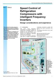
Animation - KIMO Refrigeration HVAC Ltd.
Animation - KIMO Refrigeration HVAC Ltd.
Animation - KIMO Refrigeration HVAC Ltd.

You also want an ePaper? Increase the reach of your titles
YUMPU automatically turns print PDFs into web optimized ePapers that Google loves.
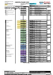
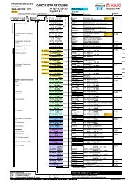
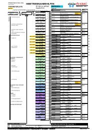
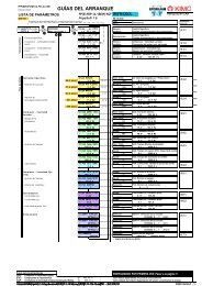
PFP-MM-CP-RAH-12_FS1.6.2-100101224.014-162/01PARAMETER LISTUSA unitsFrigoSoft16.2_2aXXXT4-6 1.3xMeasured valuesAutomatic to OPERATOR menu approx. 2 s after switching on- Compressor rack:- Variable-speed Compressor(VsC):- Fixed-speed Compressor(FsC):- Variable-speed Fans (VsF),Condenser:MEOPERATORmenu at level 1QUICK START GUIDEMEFP (E) FEP-14 / iSE(P) RCFFrigoSoft 1.603:pe____pc PRESY.Y YY.Y bar04:pe____pc P DVY.Y Y.Y%07:VsC ELEC A_HzY.Y Y.Y Hz08:FsC ACTV_POSSY Y15:VsF CD ACT VLYYY.Y %REFR/COOLFS 1.6.2-2xTypeValueMeasuredvaluesDeviationsMeasuredvaluesMeasuredvaluesMeasuredvaluesDescriptionCompressor rack:Evaporating and condensing pressureCompressor rack:Evaporating and condensing pressureVariable-speed Compressor:Motor current, Motor frequencyFixed-speed Compressors:Number active / possibleVariable speed Fan, cond.:0.00 ... 100.00 (%)<strong>Refrigeration</strong> <strong>HVAC</strong>Furtherinformation9.1.19.1.29.1.19.1.3SettingsCompressor rack- Suction pressure:36.3 psig47.9 psig30:pe MINIMUM 2.5 bar33:pe SETPOINT 3.3 bar- 16 °C*- 10 °C*Limit value_._ barSetting 1_._ barpe, Stop value "Pump Down limit":-0.5 ... 7.0 barpe, Setpoint:-0.5 ... 7.0 bar8.3.287.0 psig39:pe MAXIMUM 6.0 bar 7 °C*Limit value_._ barpe, Maximum value:-0.5 ... 7.0 bar-Discharge / condensingpressure:251 psig43:pc SETPOINT 17.3 bar40 °C*Setting 1_._ barpc, Setpoint:0.0 ... 30.0 bar8.3.4336 psig49:pc MAXIMUM 23.0 bar51 °C*Limit value_._ barpc, High Limit:0.0 ... 30.0 barVariable-speed Compressor(VsC)- Frequencyrange:- Resonanceavoidance:- Time settings:- Lubrication:Fixed-speed Compressor(FsC)- Time settings- Rack design:Controllerspe Controller:- - pc Controller:- VsF Minimum speed:Other settings61:VsC CURR MAX FFF.FF A62:VsC FREQ MAX 60.0 Hz65:VsC FREQ MIN 25.0 Hz66:VsC SKIP FREQ0.00 Hz67:VsC SKIP BAND 0.0 HzLimit value___._ ALimit value__._ HzLimit value__._ HzSetting__._ HzSetting__._ HzVsC, Maximum current:0.00 ... 999.99 AVsC, Maximum frequency:15.0 ... 90.0 HzVsC, Minimum frequency:15.0 ... 90.0 HzVsC, Skip frequency:15.0 ... 90.0 HzVsC, Skip frequency band:0.0 ... 10.0 Hz8.4.370:VsC tinh TIMELimit value VsC, Minimum OFF time: FFF.F s___._ s0.1 ... 3000.0 s* Factory setting for R404A71:VsC thld TIME Setting VsC, Hold time (time at fmin following oil pulse):10.0 s __._ s 0.1 ... 3000.0 s74:VsC tmon fminSettingVsC: Monitoring time at fmin: 600.0 s__._ s0.0 ... 3000.0 s76:VsC toil STRTSettingVsC, Oil lubrication pulse time: 4.0 s__._ s0.1 ... 3000.0 s8.4.481:FsC ton DLYSettingFsC, Switch-on delay: FFF.0 s___._ s0.1 ... 3000.0 s8.5.182:FsC toff DLYSettingFsC, Switch-off delay: FF.0 s__._ s0.1 ... 3000.0 s83:FsC NUMBERSelectionFsC, Number of compressors:1_0 ... 291:pe CNTRL P-GNSettingpe controller, Proportional gain:F.00 _._0.10 ... 100.008.6.192:pc CNTRL P-GNSettingpc controller, Proportional gain: 10.0_._0.1 ... 100.08.6.293:VsF CD MIN SDSettingVar.-speed Fan, cond., min. speed: 15.00__._ %0.00 ... 100.00A1:AOUT1 FUNCTNSelectionAOUT1 - Function selection:INPUT 0_INPUT 0...3 (VsF)8.7.1A4:DOUT1 FUNCTN Selection DOUT1 - Function selection:INPUT 2 _ INPUT 0...7 (CC)A5:DOUT3 FUNCTNSelectionDOUT3 - Function selection:INPUT 0_INPUT 0...7 (FsC1)A9:LANGUAGESelectionLanguage selection:ENGLISH_______________ ENGLISH ... NEDERLANDS8.7.38.4.18.4.2Key for abbreviationsVsC: Variable-speed CompressorFsC: Fixed-speed CompressorVsF: Variable-speed fans (Condenser / Dry cooler)= YYY.YY % FFF.0 s::FIRST TIME POWER UP: Go to page 11Measured value depending on operating pointFactory default value depending on frame size and rated power<strong>KIMO</strong> R<strong>HVAC</strong> - 1 -
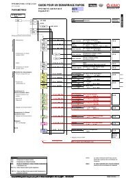
Explanation of adjustable operating pressures:49:pc MAXIMUM43:pc SETPOINTPressure39:pe MAXIMUM33:pe SETPOINT30:pe MINIMUMHighambienttemp.Suggested refrigeration settings:Based on EN 1290030:pe MINIMUM 2.5 bar33:pe SETPOINT 3.3 bar39:pe MAXIMUM 6.0 bar43:pc SETPOINT 17.3 bar49:pc MAXIMUM 23.0 barFactory settingR404A / R507LT MT HT-40 °C/ -16 °C/0.3 2.5R407CMT HTR22LT MT0 °C/ -16 °C/ 0 °C/ -37 °C/ -16 °C/5.0 1.5 3.6 0.2 1.9R134aMT HT0 °C/ -16 °C/ 0 °C/ -16 °C/4.0 0.6 1.9 3.6-35 °C/ -10 °C/ 5 °C/ -10 °C/ 5 °C/ -32 °C/ -10 °C/ 5 °C/ -10 °C/ 5 °C/ -10 °C/ 5 °C/0.6 3.3 6.0 2.2 4.5 0.5 2.6 4.8 1.0 2.5 4.7 8.35 °C/ 5 °C/ 5 °C/ 10 °C/ 10 °C/ 10 °C/ 10 °C/ 10 °C/ 12 °C/ 12 °C/ 12 °C/ 12 °C/6.0 6.0 6.0 5.5 5.5 6.8 6.8 6.8 3.4 3.4 10.5 10.540.. °C/ 40.. °C/ 40.. °C/ 40.. °C/ 40.. °C/ 40.. °C/ 40.. °C/ 40.. °C/ 40.. °C/ 40.. °C/ 40.. °C/ 40.. °C/17.3 17.3 17.3 16.5 16.5 14.3 14.3 14.3 9.2 9.2 23.3 23.352 °C/ 52 °C/ 52 °C/ 52 °C/ 52 °C/ 52 °C/ 52 °C/ 52 °C/ 55 °C/ 55 °C/ 55 °C/ 55 °C/23.0 23.0 23.0 22.2 22.2 19.3 19.3 19.3 13.9 13.9 37.4 37.4HTR410AMT HT0 °C/7.0R404A/R507R407CR22R134aR410ALP:HP:-0.5 ... 7.0 bar0 ... 30 bar0 ... 25 bar0 ... 40 barPressure transducers**Modified settings required, see Special Settings, page 4***DiagnosticsElectrical values:DIAGNOSTICSmenu at level 1MEDRIVE FREQUENCY= YY.YY HzMOTOR CURRENT A= YY.Y AMOTOR CURRENT %= YY.YY %DC LINK VOLTS= YYY VBASE FREQ ACTIVE= YY.Y HzBASE VOLT ACTIVE= YYY.Y VTERMINAL VOLTS= YYY VTORQUE FEEDBACK= YY.YY %FIELD FEEDBACK= YY.YY %ELECTRICAL POWER= YY.Y kWELECTRICL ENERGY= YYY kWhInternal valueMeasuredvalueInternal valueMeasuredvalueInternal valueInternal valueMeasuredvalueInternal valueInternal valueMeasuredvalueMeasuredvalueVariable-speed Compressor:Motor FrequencyVariable-speed Compressor:Motor current [A]Variable-speed Compressor:Motor current [%]Variable-speed Compressor:DC link voltageVariable-speed Compressor:Active base frequencyVariable-speed Compressor:Active base voltageVariable-speed Compressor:Motor voltageVariable-speed Compressor:Calculated torqueVariable-speed Compressor:Calculated magnetic motor fieldVariable-speed Compressor / Rack:Calculated / Measured electrical powerVariable-speed Compressor / Rack:Calculated / Measured electrical energy9.2.1Stage controller:SC STAGE NUMBER= YSC CAPACITY CNTR= YYYYYSC OUTPUT= YYYYSCC OUTPUT 1= YYYYYSCC OUTPUT 2= YYYYYSCC OUTPUT 3= YYYYYInternal valueCommandInternal valueCommandCommandInternal valueCompressor rack:Number of stagesCompressor rack:Capacity Control activatedCompressor rack:Output control signalCompressor rack:Output control signal 1Compressor rack:Output control signal 2Not in use9.2.2SCC OUTPUT 4= YYYYYInternal valueNot in useSC CAPACITY= Y.YYSC CAPACITY %= YY.YY %Internal valueInternal valueCompressor rack:Calculated total powerCompressor rack:Calculated total power in %SC DIAGNOSTIC= YInternal valueCompressor rack:Diagnostics- 2 - <strong>KIMO</strong> R<strong>HVAC</strong>
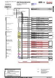
DiagnosticsAnalog inputs:ANALOG INPUT 1= YYY.YY %ANALOG INPUT 2= YYY.YY %ANALOG INPUT 3= YYY.YY %AIN1 (X2:2)Analog input 1AIN2 (X2:3)Analog input 2Analog input 3pe, Suction-pressure transducer:4 ... 20 mA; 0.0 ... 100.0 %pc, High-pressure transducer:4 ... 20 mA; 0.0 ... 100.0 %Not used6.3.1 /ANALOG INPUT 4= YYY.YY %Digital input 3Not usedAnalog outputs:ANALOG OUTPUT 1= YYY.YY %ANALOG OUTPUT 2= YYY.YY %AOUT1 (X2:6)Analog output 1Analog output 2VsF speed / VsC speed /- / -Not used6.3.2ANALOG OUTPUT 3= YYY.YY %Analog output 3Not usedDIGITAL I/O= YYYY >>MenüDigital inputs and outputs5.2Digital inputs:DIGITAL INPUT 1= YYYYYDIGITAL INPUT 2= YYYYYDIGITAL INPUT 3= YYYYYDIGITAL INPUT 4= YYYYYDIGITAL INPUT 5= YYYYYDIGITAL INPUT 6= YYYYYDIGITAL INPUT 7= YYYYYSAFETY CIRCUIT= YYYYYDIN1 (X2:12)Digital input 1DIN2 (X2:13)Digital input 2DIN3 (X2:14)Digital input 3DIN4 (X2:15)Digital input 4DIN5 (X2:16)Digital input 5DIN6 (X2:17)Digital input 6DIN7 (X2:18)Digital input 7DIN8 (X2:19)Digital input 8Enable (Start)Force lubrication speedNot usedNot usedNot usedFsC Safety circuits without fault /Activate VsC continuous operationActivate emergency operationSafety circuit "Ready" (No fault)5.2.1-45.35.35.35.4Digital outputs:DIGITAL OUTPUT 1= YYYYYDIGITAL OUTPUT 2= YYYYYDIGITAL OUTPUT 3= YYYYYDOUT1 (X:21-22)Digital output 1DOUT2 (X2:23-24)Digital output 2DOUT3 (X2:25-26)Digital output 3Ready (Health)OperatingActivate FsC1(Fixed-speed Compressor 1)6.3.46.3.46.3.4Analog outputs used as relayoutputs:ANALOG OUTPUT 1= YYYYYANALOG OUTPUT 2= YYYYYANALOG OUTPUT 3= YYYYYAOUT1 (X2:6)Analog output 1AOUT2 (X3:7A-7B)Digital output A2AOUT3 (X3:8A-8B)8B)Digital output A3- / - /- / No pc limitingNot usedNot used6.3.26.3.46.3.4Setpoints:SPEED DEMAND= YYY.YY %REMOTE SETPOINT= YYY.YY %FREQ SETPOINT= YY.YY HzCOMMS SETPOINT= YYY.YY %LOCAL SETPOINT= YYY.YY %JOG SETPOINT= 10.00 %Internal valueInternal valueInternal valueInternal valueInternal valueInternal valueVsC: Actuating value of Freq.:% of maximum frequencyRemote setpoint:% of maximum frequencyVsC Frequency Setpoint:FrequencyComms command setpoint:% of maximum frequencyLocal setpoint:% of maximum frequencyJog setpoint:% of maximum frequency8.1.13Trips:ACTIVE TRIPS= YYYY >>ACTIVE TRIPS+= YYYY >>WARNINGS= YYYY >>WARNINGS+= YYYY >>FIRST TRIP=TYY:YYYYYYYYYYYTripsTripsWarningWarningTripActive trips:First setActive trips:Second setWarnings:First setWarnings:Second setTrip which caused shut down10.2-4TRIP 1 (NEWEST)=TYY:YYYYYYYYYYYTripTrip 1 (newest) which caused shut downTRIP 1 TIME=YYYYYYYYY sTripTime trip 1 occuredTRIP 10 (OLDEST)=TYY:YYYYYYYYYYYTripTrip 10 (oldest) which caused shut downTRIP 10 TIME=YYYYYYYYY sTripTime trip 10 occuredState indications:TIME IN SERVICE=YYYYYYYYYYY sTIME RUNNING=YYYYYYYYYYY sSTART COUNT=YYYYYYYYYYYATTEMPTS LEFT= YYTIME LEFT= YYYY.Y sBRAKING=YYYYSEQUENCER STATE=YYYYYYYYYYYYYYYMOTOR STATE=YYYYYYYYYYYYYYYMeasuredvalueMeasuredvalueMeasuredvalueInternal valueInternal valueStatusStatusStatusTime powered upTime VsC runningNumber of VsC startsAutorestart logic:Attempts leftAutorestart logic:Time to next start attemptiSpeed:Chopper activeiSpeed operating status:Sequencer control stateVsC operating status:Sequencer control state10.2-4<strong>KIMO</strong> R<strong>HVAC</strong> - 3 -
SettingsBasic settings:QUICK SETUPmenu at level 1MELANGUAGEENGLISHAPPLICATION SAVED APPACCESS LEVELOPERATORSELECT UNITS 1DEFAULTSELECT UNITS 2DEFAULTSELECT UNITS 3DEFAULTSELECT UNITS 4DEFAULTSelection__________Selection_____________Selection_____________Selection_____________Selection_____________SelectionSelectionENGLISH, DEUTSCH, FRANCAIS, ESPANOL, ITALIANO, SVENSK,POLSKI, PORTUGUES, NEDERLANDSR<strong>HVAC</strong> ApplicationMenu access levelDisplayed pressure units:DEFAULT: bar; ALTERNATE: psigNot usedNot usedNot usedSpecial settings:REFRIGERANTCUSTOMDATA 1 VALUE 1 0.00DATA 1 VALUE 2 1.00DATA 1 VALUE 3 0.00DATA 1 VALUE 4 0.00DATA 1 VALUE 5 0.00RFARFBRFCSelectionSelection_.__Selection_.__SettingSettingSettingNot usedPressure Transducer pe [bar]:0.00: -0.5...7.0 1.00: 0...25 2.00: 0...30 3.00: 0...60Pressure Transducer pc [bar]:0.00: 0...25 1.00: 0...30 2.00: 0…40 3.00: 0...160Not usedNot usedNot usedDATA 1 VALUE 6 0.00DATA 1 VALUE 7 0.00DATA 1 VALUE 8 0.00DATA 1 LOGIC 1FALSEDATA 1 LOGIC 2FALSEDATA 1 LOGIC 3FALSEDATA 1 LOGIC 4FALSESettingSettingSettingSelectionSelection_________Selection_________SelectionNot usedNot usedNot usedNot usedDigital input DIN6:Activate VsC not stopDigital output DOUT1:Multiplexed multi functionNot usedDATA 2 VALUE 1 0.00DATA 2 VALUE 2 1.20DATA 2 VALUE 3 20.00DATA 2 VALUE 4 20.00DATA 2 VALUE 5 0.00SettingSetting___.__Setting___.__Setting___.__SettingNot usedFactor for increase in fmin when limitingSuction pressure controller:PID I time constantCondensing pressure controller:PID I time constantNot usedDATA 2 VALUE 6 0.00DATA 2 VALUE 7 0.00DATA 2 VALUE 8 0.00DATA 2 LOGIC 1FALSEDATA 2 LOGIC 2FALSEDATA 2 LOGIC 3FALSESettingSettingSettingSelection_________SelectionSelectionNot usedNot usedNot usedEnable automatic oil speed up after delayedminimum capacityNot usedNot usedDATA 2 LOGIC 4FALSESelectionNot usedVsC motor settings:MAX FREQ 60.00 HzMIN FREQ 25.00 HzSetting__.__ HzSetting__.__ HzVsC: Maximum frequencyVsC: Minimum frequencyMOT RATED VOLTS 400.0 VMOT RATED FREQ 50.00 HzMOT BASE FREQ 55.00 HzMOT RATED CURRNT YY.YY ASetting___._ VSetting__.__ VSetting__.__ HzSetting___.__ AVsC: Motor rated voltageVsC: Motor rated frequencyVsC: Motor base frequencyVsC: Motor maximum currentFIXED BOOST YY.YY %AUTO BOOST YY.YY %Setting__.__ %Setting__.__ %VsC: Motor fixed boostVsC: Motor auto boostMIN BASE FREQ 25.00 HzSetting__.__ HzVsC: Motor minimum base frequencySKIP FREQ 1 0.0 HzSKIP BAND 10.00 HzSetting__._ HzSetting_._ HzVsC: Skip frequency 1VsC: Skip band 1SKIP FREQ 2 0.0 HzSKIP BAND 2 0.0 HzSetting__._ HzSetting_._ HzVsC: Skip frequency 2VsC: Skip band 2- 4 - <strong>KIMO</strong> R<strong>HVAC</strong>
Energy meter:Serial communications:ENERGY MET RESETFALSEENERGY MET MODE INTERNALENERGY MET SCALE 1.0 kWP3 EI ASCII UID1MDBS RTU ADDRESS0MDBS RTU PARITY0Selection_________Selection_________Setting__._ kWSetting_Setting_Selection_________Energy meter:Reset at FALSE --> TRUE --> FALSEEnergy meter:Mode: Internal= VsC; External= RackEnergy meter:Scale: 1 kWh each pulseP3 RS232 port with EI ASCII protocoll:Unit Identifier addressNot in useNot in useAnalog input types:AIN 1 TYPE 4..20 mAAIN 2 TYPE 4..20 mAAIN 3 TYPE 0..+10 VAIN 4 TYPE 0..+10 VSelection_________Selection_________SelectionSelectionAnalog input AIN1:TypeAnalog input AIN2:TypeNot in useNot in useCompressor rack:SC FsD+ DELAY FFF sSC FsD+ FORCEFALSESC FsD- DELAY FF sSC FsD- FORCEFALSESC FsD RUN MAX 6000 sSC FsD RUN MIN 60 sSC FsD STOP MAX 600 sSC FsD STOP MIN 60 sSC CC ACTIVE MAX 300 sSC CC RECOVR MIN 15 sSC FAST STOP DLY2 sSC FsD TOT OP RSFALSESC FsD NMB ST RSFALSESC STAGE NMB MAX1SC LOGIC TYPE1SC CODE TYPE0SC CODE OFFSET0SC CC OUT0SC VsD CAPACITY 100.00SC VsD CC CPCTY 100.00 %SC FsD FREQ 50.00 HzSC FsD0 CAPACITY 100.00SC FsD0 CC CPCTY 0.00 %SC FsD1 CAPACITY 100.00SC FsD1 CC CPCTY 100.00 %SC FsD2 CAPACITY 100.00SC FsD2 CC CPCTY 100.00 %SC FsD3 CAPACITY 100.00SC FsD3 CC CPCTY 0.00 %SC FsD4 CAPACITY 100.00SC FsD4 CC CPCTY 0.00 %Setting___ sSelection_________Setting___ sSelection_________Setting____ sSetting___ sSetting____ sSetting___ sSetting___ sSetting___ sSetting___ sSelection_________Selection_________Setting_Setting_Setting_Setting_SettingSetting___.__Setting___.__ %Setting__.__ HzSettingSettingSetting___.__Setting___.__ %Setting___.__Setting___.__ %SettingSettingSettingSetting_Stage controller:FsC switch-on delayStage controller, Manual force:One stage more at FALSE>TRUE>FALSEStage controller:FsC OFF delayStage controller, Manual force:One stage less at FALSE>TRUE>FALSEStage controller:FsC maximum run timeStage controller:FsC minimum run timeStage controller:FsC maximum stop timeStage controller:FsC minimum stop timeStage controller, Capacity Control:FsC CC maximum active timeStage controller, Capacity Control:FsC CC minimum recovery timeStage controller:FsC OFF delay at fast stopStage controller:FsC reset total operating timesStage controller:FsC reset total start countStage controller:FsC maximum number of stagesStage controller, FsC type of logic:0: Normal; 1: Swop 1 (FsC); 2: Swop 2Stage controller, FsC type of code:0: MBC; 1: GBC; 2: MGBCStage controller: FsC code offset:Stage controller:Internal Capacity Control output activatedStage controller:Set VsD capacityStage controller:Set VsD capacity when capacity controlledStage controller:Set FsD frequencyNot usedNot usedStage controller:Set FsD1 capacityStage controller:Set FsD1 capacity when capacity controlledStage controller:Set FsD2 capacityStage controller:Set FsD2 capacity when capacity controlledNot in useNot in useNot in useNot in useSC CAPACITY TYPE1SelectionStage controller:Set capacity calculation typeSC DIAGNOST SEL1Selection_Stage controller:Diagnostic selectAVAILABLE SOON0: FsD with longest run time 1: Longest run time2: FsD with longest stop time 3: Longest stop time4: Run/Stop 11: Total 18: Total FsD1:: times : running : number :10: 17: times 24: of starts FsD7:Output value:DIAGNOSTICSSC DIAGNOSTIC<strong>KIMO</strong> R<strong>HVAC</strong> - 5 -
PFP-MM-CP-RAH-12_FS1.6.2-1001REFR/COOL01224.014-162/01POWER SECTIONPower connectionsFP(E) FEP-14 / iSE(P) RCFFrigoSoft 1.6FS 1.6.2-2x<strong>Refrigeration</strong> <strong>HVAC</strong>FP 4.0FEP / iS RCF9.5:Power wiringFP 6.0FEP / iS RCF14:Power wiringFP 7.5 ... 90FEP / iS RCF23 ... 205:Power wiringFP 7.5 ... 90FEP / iS RCF23 ... 205:Power wiring with two compressors- 6 - <strong>KIMO</strong> R<strong>HVAC</strong>
PFP-MM-CP-RAH-12_FS1.6.2-100101224.014-162/01FP(E) FEP-14 / iSE(P)RCFFrigoSoft 1.6REFR/COOLFS 1.6.2-2x<strong>Refrigeration</strong> <strong>HVAC</strong>Power terminalsTerminal / DesignationSignal / FunctionExplanationFurtherinformationPE, PE FP ...30FEP-EMC / iS RCF23 ... 73:- Observe all safety and EMC requirementsProtective earth connections(both to be earthed)PEFP 37... FEP-EMC / iS RCF87...:Protective earth connectionL1Three phases of voltage supply- Ensure that supply voltage agrees with data onL2/NFrigoPack / iSpeed name plateL3DC+- Do not use otherwise risk of damage to FrigoPack / iSpeed(DBR)DC-M1/UCompressor motor- Variable-speed Compressor via safety contactorM2/VM3/WPEProtective earth connection tocompressor motor(DBR+)- Do not use otherwise risk of damage to FrigoPack / iSpeed(DBR-)AUX1 Only with: FP 55...FEP-EMC / iS - Supply externallyAUX22AC 230 supply for equipment fan7.7.17.7.17.7.1/7.7.27.7.26.76.8.4Terminals for motor protectionTerminal / Designation Signal / Function ExplanationX2:MOT/TEMPAlternative a),Without processing:-Thermistor protection is processed in safety circuit,these two terminals must be linkedFurtherinformation6.2Alternative b),Direct processing of motor thermistors:- Connect motor thermistors between these two terminalsAlternative c), -Processing an external thermistor relay:Alternative d),Processing an external thermistor relay:Connect the "normally open" contacts of externalthermistor relay (e.g. KRIWAN) between these twoterminals- Connect the "Normally open" contacts of an auxiliaryrelay wired to an external thermistor relay (e.g. KRIWAN)between these two terminals.AC 230 VL21FrigoPack:MOT/TEMP FrigoPack:MOT/TEMP RSFrigoPack:MOT/TEMPA/TH1AB/TH1BA/TH1AB/TH1BA/TH1AB/TH1BRSFrigoPack:MOT/TEMPA/B/TH1ATH1BAC 230 VL22AC 230 VAC 230 VLockoutLockout1 2B1B21 2B1B2a) b) c) d)<strong>KIMO</strong> R<strong>HVAC</strong> - 7 -
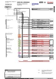
PFP-MM-CP-RAH-12_FS1.6.2-100101224.014-162/01FP(E) FEP-14 / iSE(P) RCFFrigoSoft 1.6REFR/COOLFS 1.6.2-2x<strong>Refrigeration</strong> <strong>HVAC</strong>CONTROL SECTIONControl connections1 2 1 22 A B 3 A BFF5G14P19PX2:3 5 11 12 131617181920DIN4DIN5DIN6DIN7DIN8+24 VAnalog Input from pressure transducer forSuction Pressure pe (LP)Analog Input from pressure transducer forDischarge / Condensing Pressure pc (HP)Digital Input to enable Emergency ControlDigital Input to monitor Safety Circuit of theVsC compressorPTPT4...20 mA: -0.5...7.0 bar4...20 mA: 0...30 bar13P16P18P0 VAIN1AIN2AIN40 VAnalog Input from temperature transducerfor Exhaust-Gas Temperature (PT1000)Digital input for Enable (Start)Digital Input to force to Lubrication SpeedDigital Input to monitor Safety Circuit of theFsC compressors12P15P17P121415iSpeedDIN1DIN2DIN3AOUT1(I max : 5 mA)DOUT1DOUT2DOUT3621 222324 25 26+MAM6GVsF Condenser fan: ActuatingValue /-- VsC: Measured speed /Analog Outputdepending onsetting:- VsC: Control of hot gas bypassvalve /pc limiting-Depending on setting:"VsC Ready for operation" /-Relay dependingon setting:"VsC Operating"to control auxiliaries such as:Relay:- Crankcase heater, Condenserfan, Start unloaderFsC1: Activate /FsC2: Activate /Capacity Control /--No high-pressure limiting/Minimum capacity /Minimum capacity delayed /pe>=pemax/Compressor swop-Relay output dependingon setting:----A1:AOUT1 FUNCTNA4:DOUT1 FUNCTNA5:DOUT3 FUNCTNVsC:Variable-speed CompressorFsC:Fixed-speed CompressorFP(E) FEP-14 / iSE(P) RCFFrigoSoft 1.6Special settingsA1:AOUT1 FUNCTN A4:DOUT1 FUNCTN A5:DOUT3 FUNCTNSetting Function Setting FunctionSetting--INPUT 0INPUT 1VsF: Actuating ValueVsC: Measured speed (Frequency)---INPUT 0INPUT 1INPUT 2FsC1: ActivateFsC2: ActivateActivate capacity control---INPUT 2Not used-INPUT 3No high-pressure limiting--INPUT 3No high-pressure limiting----INPUT 4 Minimum capacityINPUT 5 Minimum capacity delayedINPUT 6 pe >= pemaxINPUT 7 General purpose swop signalFunctionINPUT 0 FsC1: Activate- INPUT 1 FsC2: ActivateINPUT 2 Activate capacity controlINPUT 3No high-pressure limiting- INPUT 4 Minimum capacity- INPUT 5 Minimum capacity delayed- INPUT 6 pe >= pemax- INPUT 7 General purpose swop signalAVAILABLESOON- 8 - <strong>KIMO</strong> R<strong>HVAC</strong>
PFP-MM-CP-RAH-12_FS1.6.2-100101224.014-162/01Terminals for control functionsFP(E) FEP-14 / iSE(P)RCFFrigoSoft 1.6REFR/COOLFS 1.6.2-2x<strong>Refrigeration</strong> <strong>HVAC</strong>Terminal / Designation Signal / FunctionExplanation2A - 2B AIN1 Analog Input from pressure transducer for SuctionPressure pe (LP):- Suction pressure pe (LP), must be used- Suitable pressure transducer:0 mA: Fault- A REF-P-TRANSD-LP7+PL4 mA: -0.5 bar- Connections:20 mA: +7.0 bar- 1 --> 2A; 2 --> 2B3 A - 3 B AIN2 Analog Input from pressure transducer for Discharge - Discharge / condens. pressure Pc (HP), optional use/ Condensing Pressure pc (HP):- Suitable pressure transducer:0 mA: Not used- A REF-P-TRANSD-HP30+PL4 mA: 0.0 bar- Connections:20 mA: +30.0 bar- 1 --> 3A; 2 --> 3B5 - 5G AIN4 Not usedFurtherinformation7.7.47.7.46 - 6G AOUT17 AOUT28 AOUT3Analog Output (5 mA max. load):- Depending on setting:0 V:+10 V:0.00 % Actuating value100.00 % Actuating valueA1:AOUT1 FUNCTN- 0: VsF Condenser fan: Actuating Value /- 1: VsC: Measured speed /- 2: Not usedDigital Output with ext. special relay:- 3: pc limitingOpen:Closed:Not activatedActivated- Only use special relay A RELAY-DC12V (available asaccessory)Not usedNot used7.7.312P - 12 DIN1 Digital input for Enable (Start):- Enable / Start5.2.1-4,0 V: Stop7.7.3+24 V: Enable13P - 13 DIN2 Digital Input to force to Lubrication Speed:- Force Lubrication Speed 5.3,- Optional use7.7.30 V: Normal+24 V: Lubrication speed- Requires external timer14 DIN3Not used15 DIN4Not used:16 DIN5 Not used:- pc Setpoint selection- Optional use17P - 17 DIN6 Digital Input to monitor Safety Circuit of the FsC - FsC Safety circuits without fault 5.3,compressors:(Enables swop logic if all FsCs are available) 7.7.30 V: >=1 FsCs not available or faulty+24 V: All FsCs available and fault free- Alternative use: VSC continuous operation18P - 18 DIN7 Digital Input to enable Emergency Control:- Emergency operation (Operation with a defect 5.3,inverter or compressor)7.7.30 V: No Emergency Control- Optional use+24 V: Activate Emergency Control19P - 19 DIN8 Digital Input to monitor Safety Circuit of the VsCcompressor:- VsC Safety circuit without fault- Must be used5.4,7.7.30 V: External fault- Interrupt if there is a fault+24 V: Normal (no fault)(Required to stop inverter operation)21 - 22 DOUT1 Relay output "VsC Ready":- Depending on setting:5.4,Open: No supply, fault or alarmRelay:7.7.3Closed: Ready (no fault)A4:DOUT1 FUNCTNOptional additional functions with multiplex:- 0: FsC3: Activate /- 1: Capacity Control /Relay "Ready+Multiplex":- 2: No high-pressure limiting/Open: No supply, fault or alarm- 3: Minimum capacity /Closed: VsC Ready OR (VsC Operating ANDMultiplexed Signal)- 4: Minimum capacity delayed /- 5: pe>=pemax/#NVEnablemultiplex:DATA 1 LOGIC 3: FALSE#NV- Max contact load: AC 230 V, 250 VA23 - 24 DOUT2 Relay output "VsC operating": - "VsC Operating"to control auxiliaries such as:5.4,7.7.3Crankcase heater, Condenser fan, Start unloaderOpen: VsC: Inhibited / Not operatingClosed: VsC: Starting / Operating - Max contact load: AC 230 V, 250 VAVsC: Variable-speed Compressor (Inverter operation)VsF: Variable-speed fan (condenser)FsC: Fixed-speed Compressor<strong>KIMO</strong> R<strong>HVAC</strong> - 9 -
Terminal / DesignationSignal / FunctionExplanation25 - 26 DOUT3 Relay output to activate FsC1: - Depending on setting: 7.7.3Open: Not activatedA5:DOUT3 FUNCTNClosed: Activated - 0: FsC1: Activate /- 1: FsC2: Activate /- 2: Capacity Control /- 3: No high-pressure limiting/- 4: Minimum capacity /- 5: Minimum capacity delayed /- 6: pe>=pemax/- 7: Compressor swop- Max contact load: AC 230 V, 250 VAVsC: Variable-speed Compressor (Inverter operation)VsF: Variable-speed fan (condenser)FsC: Fixed-speed CompressorFurtherinformationSafety and control circuitsk58Important note:This simplified overview of the safety and control wiring of a typical system only includes the wiring for AUTOMATIC operation.It is recommended that the following additional functions are included in the control system:- MANUAL mode of operation using a "Pump Down" circuit- A security circuit to provide:- Automatic selection of MANUAL operation in an emergency- Means of stopping the evaporators if compressors are not available.- Standard suggestions for the safety and control wiring with these features are available on request.- <strong>KIMO</strong> R<strong>HVAC</strong> can assist with the planning of complex systems or systems with special requirements.- 10 - <strong>KIMO</strong> R<strong>HVAC</strong>
<strong>KIMO</strong> R<strong>HVAC</strong> - 11 -PFP-MM-CP-RAH-12_FS1.6.2-100101224.014-162/01FP(E) FEP-14 / iSE(P)RCFFrigoSoft 1.6REFR/COOLFS 1.6.2-2x<strong>Refrigeration</strong> <strong>HVAC</strong>FIRST TIME POWER UPElectrical safety:UL compliance where appropriate:EMC compliance:Language selection:Selection of this refrigeration application,Restoring factory settings:Storing configurations and parameter changes:Pressure transducers:Ensure that all recommendations in the Product Manual have been adheredtoEnsure that all recommendations in the Product Manual for UL compliancehave been adhered toEnsure that all recommendations in the Product Manual for EMCcompliance have been adhered to- Power up holding key 'PROG' depressed- Release key 'PROG' and press key 'M'- Arrow to left of second line should appear- Select required language with the arrow keys 'UP' / 'DOWN'- Press key 'E' 4x followed by key 'M' 2x- OPERATOR menu ist selected- Power up while holding arrow keys 'UP' and 'DOWN' depressed.RESTORE DEFAULTS | UP TO CONFIRMshould be shown- Press arrow key 'UP'- A short moment laterAPPLICATION | NONEwill be shown- Press key 'M'- Arrow to left of second line should appear- Select configuration: FrigoSoft16.2_1xwith arrow keys 'UP'/'DOWN'- Press key 'E', wait a short moment, press key 'E' 2x and verify if correctconfiguration has been- Store loaded configuration as follows- Press key 'PROG' 3s longSAVE CONFIG | UP TO CONFIRMshould be shown- Press arrow key 'UP' and wait until following messageis shown in the second line:SAVING -> COMPLETE- Press key 'E' 2x followed by key 'M' 2x- OPERATOR menu ist selectedThis refrigeration application is designed for use with the followingpressure transducers:- pe: -0.5 ... 7.0 bar -7.25 ... 101.53 psi Relative (gauge) pressure- pc: 0 ... 30 bar 0.00 ... 435.11 psi "WARNING: Only use approved pressure transducers
PFP-MM-CP-RAH-12_FS1.6.2-100101224.014-162/01FP(E) FEP-14 / iSE(P)RCFFrigoSoft 1.6REFR/COOLFS 1.6.2-2x<strong>Refrigeration</strong> <strong>HVAC</strong>TROUBLE SHOOTING LISTPROBLEMPOSSIBLE CAUSEHints for fault findingREMEDIES*** TRIPPED ***T01:OVERVOLTAGE* Voltage of supply too high- Measure and document the voltage in all three input phases - Rectify cause of any high voltage* Safety contactor not controlled - Check wiring of control circuit and compare function with - Modify wiringcorrectly<strong>KIMO</strong> R<strong>HVAC</strong> recommendations* Compressor motor defect- Test if compressor motor will run with DOL supply- Replace compressor motor--Measure resistance of motor winding and compare withmanufacturer's dataCheck insulation beween phases and to earth*** TRIPPED ***T02:UNDERVOLTAGE*** TRIPPED ***T03:OVERCURRENT*** TRIPPED ***T24:IGBT DESAT* Voltage of supply too low- Measure and document the voltage in all three input phases - Rectify cause of any low voltage* Phase of supply voltage missing* Safety contactor not controlled - Check wiring of control circuit and compare function with - Modify wiringcorrectly<strong>KIMO</strong> R<strong>HVAC</strong> recommendations* Compressor motor defect- Test if compressor motor will run with DOL supply- Replace compressor motor- Measure resistance of motor winding and compare withmanufacturer's data- Check insulation beween phases and to earth* Power section of FrigoPack / iSpeed - Remove motor cable connections to FrigoPack / iSpeed - Replace FrigoPack / iSpeedfaulty- Check if operation of FrigoPack / iSpeed without a motorconnected is possible(No trip message: Probably OK;Trip message: Probably defect)- Test for operation with a small test motor* Incorrect motor connection- Check wiring to motor terminals-Modify wiring(choice of star/delta, part winding etc.)*** TRIPPED ***T05:SAFETY CIRCT* Safety contactor not controlled - Check wiring of control circuit and compare function with - Modify wiringcorrectly<strong>KIMO</strong> R<strong>HVAC</strong> recommendations* Safety device in safety circuit tripped - Check safety circuits- Reset if necessary* DC 24 V control voltage missing - Check DC 24 V control voltage at FrigoPack / iSpeed - Modify wiring- Short circuit with DC 24 V control voltage*** TRIPPED ***T06:AIN1 BREAK*** TRIPPED ***T09:I*T LIMIT*** TRIPPED ***T17:MOT OVERTEMP* Suction-pressure transducer not - Check if blue LED at the input of FrigoPack / iSpeed lights -connected or connections swapped* Transducer for suction pressure faulty - Measure current from transducer for suction pressure atinput to FrigoPack / iSpeed (must be at least +4 mA) -* Compressor start aborted- Liquid refrigerant in compressor?- Contact <strong>KIMO</strong> R<strong>HVAC</strong> for advice--Defect compressorUnsuitable FrigoPack / iSpeed settingsVerify correct connection totransducer for suction pressure.Exchange leads if necessaryReplace transducer for suctionpressure* Link TH1A-TH1B or MOT/TEMP - Check wiring of control circuit and compare function - Modify wiringmissingrecommendations* No connection to motor protectionPTC* Faulty connection to external PTCrelay* Motor winding too hot- Compressor overloaded- Contact <strong>KIMO</strong> R<strong>HVAC</strong> for advice*** TRIPPED ***T28:AIN1/2 ERROR* Transducer for pressure faulty - Measure current from transducer at input to- Replace pressure transducerFrigoPack / iSpeed (must be between 4 .. 20 mA)* Non compatible type of pressure - Check if type of pressure transducer is compatible by - Replace pressure transducer bytransducerreferring to Section 3.3 or 7.7.4 of the Product Manual compatible type*** TRIPPED ***?ANYTHING ELSE?Important note:* Anything else- Contact <strong>KIMO</strong> R<strong>HVAC</strong> for adviceThese messages are of common trips likely to occur during commissioning.Other trip messages can occur in fault conditions.When requesting advice from your supplier, always make an exact note of the following:- Exact trip message in both lines of display- Message displayed when key 'E' is pressed for at least 10 s.- 12 - <strong>KIMO</strong> R<strong>HVAC</strong>
PFP-MM-CP-RAH-12_FS1.6.2-100101224.014-162/01FP(E) FEP-14 / iSE(P) RCFFrigoSoft 1.6REFR/COOLFS 1.6.2-2xCHECKLIST AND ADDITIONAL DATA FOR PROBLEM REPORT<strong>Refrigeration</strong> <strong>HVAC</strong><strong>KIMO</strong>ProblemCodePart of installationChecklist of questions forPROBLEM REPORTTerminalsES Electrical:Yes No- Supply• Are there any known power supply interruptions ? Yes No• Do these power supply interruptions occur at the - Indicate approx. timesWhen:same time each day ?• By what amount does the supply voltage vary ?EI - Installation • Motor cable: Approx. Length ?• Motor cable: Type of screen ?• Motor cable: Screen connected to mounting plate?• Motor cable: Screen connected to metal motorhousing ?• Is a galvanised mounting plate used in the electricalenclosure ?Explanation- Indicate min. and max. voltagesAnswer/ConfirmationMin.:Max.:- Copper braid ?, Steel braid ?,Cu brd. Fe brd.- Steel conduit ?, none ?Fe cond. None- Recommendations:Yes No- Contact with largesurface area- Make sure no "pig tails"Yes No• Is a motor filter used between the FrigoPack / iSpeed - If yes, indicate <strong>KIMO</strong> product codeYes Noand the compressor motor ?Pr. Cde:MT Compressor motor• Have motor currents been entered into the PROBLEM - Operating pointYes NoREPORT ?- Start upYes NoMMMM CIFrigoPack / iSpeed:- Control and sensor • Protective Earth of FrigoPack / iSpeed connected to - Terminal: 2x PE Yes Noinputsmounting plate (two separate short connections) ?YesNo[V][V]• Is the DC P24 control voltage present ? - Terminal: 15P - GN Yes No• Connection of PTC motor protection ?- Without processingLinked- Direct processing of motor thermistorsDirekt- Processing an external thermistor relayRelay- Terminal: MOT/TEMP• Safety circuit OK ? - Terminals for measuring: 19 - GN Yes No• Enable signal present ? - Terminals for measuring: 12 - GN Yes No• External setpoint or actuating signal present ? * - Terminals for measuring: 5 - GN• Signal from suction-pressure transducer present ? - Terminals for measuring: 2B - GN• Signal from high-pressure transducer present ? * - Terminals for measuring: 3B - GN• Signal from exhaust temperature transducer present - Terminals for measuring: 4B - GN(link if not used) ? *- Terminals for measuring: 4A - 4B Yes No• * If used - Terminal for measuring: ..- Measured against green terminal: ..MM PS - Power section • Reserved for future useMM CA - Control assembly • Reserved for future useMM CS - Control settings, • Operating Mode LOCAL (Programming Pad: - Not suitable for normal operation, only useYes NoparameterLEDs SEQ + REF light) ?for commissioning:Yes No• <strong>Refrigeration</strong> / cooling parameters set ?- The following parameters must be set:Yes No30: … 50:RI<strong>Refrigeration</strong>:AP - Application • Required <strong>Refrigeration</strong> Power entered into PROBLEMYes NoREPORT ?• Number of cooling outputs entered into the PROBLEMREPORT ?• Operating pressure and temperatures entered intoPROBLEM REPORT ?• On/Off times of compressor pack entered intoPROBLEM REPORT ?- Operating pointYes No- At start upYes No- Enter variable and fixed speedYes Nocompressor times separatelyYesNo[V][V][V][V]RI IN - Installation • Reserved for future use - tbdRI PS - Pressure • Approx. cable length [m]transducers • Type of screen - Copper braid ?, Steel braid ?,Cu brd. Fe brd.- Steel conduit ?, none ?Fe cond. None• Screen NOT connected at sensor end ? Yes No• Screen connected to mounting plate of electricial - Large area contact,Yes Noenclosure ?no pig tails•Are measured pressures stable ?- Indicate range of variation within 30 sYesNope/LP pc/HP [bar]RI RC - <strong>Refrigeration</strong> • Oil present ? Yes Nocompressor • Basic data entered into PROBLEM REPORT ?Yes No<strong>KIMO</strong> R<strong>HVAC</strong> - 13 -
PFP-MM-CP-RAH-12_FS1.6.2-1001FP(E) FEP-14 / iSE(P) RCF01224.014-162/01FrigoSoft 1.6CONFIGURATION OVERVIEW / PROBLEM REPORT(Put cross in box where appropriate)REFR/COOLFS 1.6.2-2x<strong>Refrigeration</strong> <strong>HVAC</strong>Application <strong>Refrigeration</strong> No. of coolingCondenser OtherAir ConditioningoutletsRefrigerant R404A.................. R407C................... R134a....................Total refrig. PowerOtherR507A.................. R22.................... R......................... [kW]Compressor Piston No. of cylinders Scroll Screw OtherStart unloader Part Winding Variable speed OR Fixed speedNo. of1Capacity control [%] [%] [%] [%]compressorsManufacturer Model Anything specialCompressor Piston No. of cylinders Scroll Screw OtherStart unloader Part Winding Variable speed OR Fixed speedNo. of2Capacity control [%] [%] [%] [%]compressorsManufacturer Model Anything specialOperating Suction pressure High (discharge) pressure Pascal/Suction gasDischarge gasMotor currentpointbar/ temperature[°C] temperature[°C] [A]lb/in²Start upSuction pressure High (discharge) pressure gauge/Anything specialMotor currentabsolute[A]Speed variator FrigoPack/iSpeed/MotorMaster Pressure sensorsFrigoSoft refrigeration/ A/C software FS 1.6.2-2xType FP/MM Suction pressure VersionSerial number Discharge pressureModeSoft Starter FrigoPack/iSpeed/SoftCompact, LEKTROMIK Switching times of compressor packType FP/SC/LEK Variable-speedt ON [s] Fixed speedt ON [s]Serial number compressor (VsC)t PERIOD [s] compressor(s) (FsCs) t PERIOD [s]ReportList of adjustable parameters in OPERATOR menu30:pe MINIMUM2.5 bar [bar]33:pe SETPOINT3.3 bar [bar]39:pe MAXIMUM6.0 bar [bar]43:pc SETPOINT17.3 bar [bar]49:pc MAXIMUM23.0 bar [bar]61:VsC CURR MAXFFF.FF A [Hz]62:VsC FREQ MAX60.0 Hz [Hz]65:VsC FREQ MIN25.0 Hz [Hz]66:VsC SKIP FREQ0.0 Hz [%]67:VsC SKIP BAND0.0 Hz [Hz]70:VsC tinh TIMEFFF.F s [s]71:VsC thld TIME10.0 s [s]74:VsC tmon fmin30.0 s [s]76:VsC toil STRT4.0 s [s]81:FsC ton DLYFFF s [s]82:FsC toff DLYFF s [s]83:FsC NUMBER191:pe CNTRL P-GNF.0092:pc CNTRL P-GN10.0093:VsF CD MIN SD15.00A1:AOUT1 FUNCTNINPUT 0A4:DOUT1 FUNCTNINPUT 0A5:DOUT3 FUNCTNINPUT 0A9:LANGUAGEENGLISHTRIPHISTORYTRIP 1 2 3 4 5TRIP TIME(NEWEST)(OLDEST)TRIP 6 7 8 9 10TRIP TIMETIME IN SERVICE : [s]Manufacturer Agent / Partner Customer Installation<strong>KIMO</strong> <strong>Refrigeration</strong> <strong>HVAC</strong> <strong>Ltd</strong>EUR: Tel.: +49 911-8018778 Fax: +49 911-9976118applications@frigokimo.com www.frigokimo.comParker Hannifin CorporationParker Hannifin <strong>Ltd</strong>:Tel.: +44 1226-273400 Fax: +44 1226-273401eurocold@parker.com www.sporlan.comSporlan Division:Tel.: +1 636-239-1111 Fax: +1 636-239-0414svd_techsupport@parker.com www.sporlan.com- 14 - <strong>KIMO</strong> R<strong>HVAC</strong>Name:Date: