Industrial LC Plug Termination Instructions - Siemon
Industrial LC Plug Termination Instructions - Siemon
Industrial LC Plug Termination Instructions - Siemon

You also want an ePaper? Increase the reach of your titles
YUMPU automatically turns print PDFs into web optimized ePapers that Google loves.
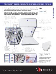
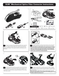
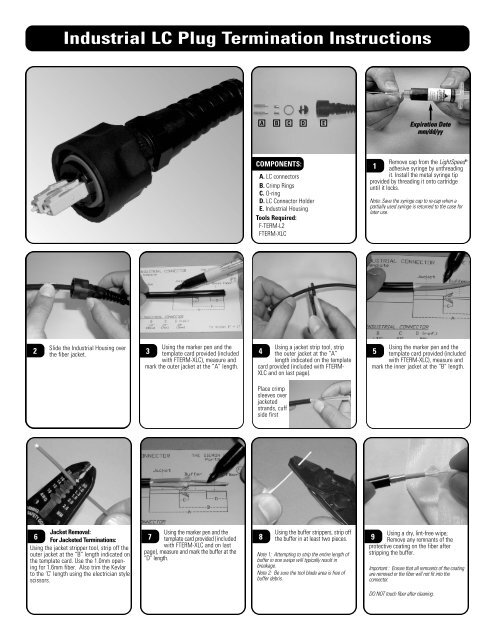
<strong>Industrial</strong> <strong>LC</strong> <strong>Plug</strong> <strong>Termination</strong> <strong>Instructions</strong>A B C D EExpiration Datemm/dd/yyCOMPONENTS:A. <strong>LC</strong> connectorsB. Crimp RingsC. O-ringD. <strong>LC</strong> Connector HolderE. <strong>Industrial</strong> HousingTools Required:F-TERM-L2FTERM-X<strong>LC</strong>Remove cap from the LightSpeed1®adhesive syringe by unthreadingit. Install the metal syringe tipprovided by threading it onto cartridgeuntil it locks.Note: Save the syringe cap to re-cap when apartially used syringe is returned to the case forlater use.2Slide the <strong>Industrial</strong> Housing overthe fiber jacket.Using the marker pen and the3 template card provided (includedwith FTERM-X<strong>LC</strong>), measure andmark the outer jacket at the “A” length.Using a jacket strip tool, strip4 the outer jacket at the “A”length indicated on the templatecard provided (included with FTERM-X<strong>LC</strong> and on last page).Using the marker pen and the5 template card provided (includedwith FTERM-X<strong>LC</strong>), measure andmark the inner jacket at the “B” length.Place crimpsleeves overjacketedstrands, cuffside firstJacket Removal:6 For Jacketed <strong>Termination</strong>s:Using the jacket stripper tool, strip off theouter jacket at the “B” length indicated onthe template card. Use the 1.0mm openingfor 1.6mm fiber. Also trim the Kevlarto the ‘C’ length using the electrician stylescissors.Using the marker pen and the7 template card provided (includedwith FTERM-X<strong>LC</strong> and on lastpage), measure and mark the buffer at the“D” length.8Using the buffer strippers, strip offthe buffer in at least two pieces.Note 1: Attempting to strip the entire length ofbuffer in one swipe will typically result inbreakage.Note 2: Be sure the tool blade area is free ofbuffer debris.Using a dry, lint-free wipe;9 Remove any remnants of theprotective coating on the fiber afterstripping the buffer.Important : Ensure that all remnants of the coatingare removed or the fiber will not fit into theconnector.DO NOT touch fiber after cleaning.
<strong>Industrial</strong> <strong>LC</strong> <strong>Plug</strong> <strong>Termination</strong> <strong>Instructions</strong>MinimumusabledepthlineExpirationDatemm/dd/yyInsert primer bottle into the10 stand. Dip the entire exposedfiber into the LightSpeed ® primer andplace in a protected area.Note: It is important that the entire exposed fiberbe coated with the primer including some portionof the buffer material. For jacketed terminations,do not be concerned with keeping the kevlarstrands out of the primer solution.Important!!11To avoid possible fiber breakage,do not insert the fiber so far that itcontacts the bottom of the primer bottle!!The primer bottle label indicates theminimum usable depth.Note: Cap the bottle when not in use to avoidcontamination. Store both primer and adhesivebetween 40° F (4.4° C) and 100° F (38° C).Remove dust cap from the12 connector and insert the adhesivesyringe tip into connector housing until itseats firmly inside. Inject the LightSpeedadhesive until a small dot of the adhesiveappears at the ferrule tip. Also inject asmall amount of adhesive into the back endof the connector. This ensures bonding ofthe buffer to the connector, strengtheningthe termination. Be careful not to overfillto prevent a backflow of adhesive.Insert the fiber into the13 connector until the buffer bottomsout inside the housing. Allow atleast 30 seconds cure time beforeproceeding. Tip: Rotate the connectorduring insertion to assist in guiding thefiber into the ferrule.Hold the flat surface of the scribe14 tool flat against the ferrule tipwith the beveled edge facing up.Carefully score the fiber close to theintersection of the ferrule tip and fiber.Score on one side only. Clean theadhesive off blade.Note: Do not use excessive pressure to preventfiber breakage and uneven fractures. If breakageoccurs see note 2 in next step.Remove the excess fiber with a15 straight, non-twisting pull anddeposit in a safe place (i.e. onto a piece oftape or in the debris container).Note1: If fiber does not readily pull off, repeatprevious step – scoring on opposite side of fiber.Note 2: Fiber pieces are difficult to see. If notproperly disposed, glass fibers may cause seriousinjury.Note 3: Be careful not to bump or brush end-facebefore polishing.16Slide the crimp sleeve over thekevlar to the base of theconnector.Using the 0.137 marked opening17 in the crimp tool, crimp thesleeve over the Kevlar and knurl bushingas shown.FIBER (A)Strain relief cuffFIBER (B)Insert the <strong>LC</strong> connectors in the18a <strong>LC</strong> connector holder as shown.Ensure that the latches are defeatedand placed under the latch lip securely.The alignment grove on the back end ofthe <strong>LC</strong> connector should “snap” into theinternal protrusions of the <strong>LC</strong> connectorholder. When assembled, both connectorsshould be seated at identicalheight.Note: To ensure proper transmitter-toreceiverpatching, be certain to18bassemble each end of a duplexassembly with the opposing orientation asshown. To help identify proper orientation it ishelpful to place the same color shrink tubing onopposite end of the same fiber strand. Ifcorrectly assembled, the final duplex assemblywill have opposite color-coded strands on the Aside as well as the B side.Slowly pull the cable slack from19 the back of the <strong>Industrial</strong>housing while aligning the <strong>LC</strong>connector holder for proper placement inthe housing.Tighten the cable strain relief cuff to amax. of 10 inch lbs. (Hand tighten)Ensure gland seal is on outer jacket.#1 Film (Gray):20 Perform an “air polish” by holdingthe connector in one handand the #1 polishing film in the other.Gently brush the dull side of the polishingfilm in a “figure 8” fashion againstthe ferrule tip to wear the small fiberprotrusion into a smoother, more polishabletip. Continue until the tip is almostflush with the ferrule.
<strong>Industrial</strong> <strong>LC</strong> <strong>Plug</strong> <strong>Termination</strong> <strong>Instructions</strong>#2 Film (Pink):21 Place the polishing pad onto a flatsurface with the rubber side facing up.Place the #2 film onto the polishing padwith the glossy side of film down.Note: Prior to polishing, clean pad surface withalcohol soaked wipe to provide for a smoothpolishing surface. This will also allow thepolishing paper to stick in place. (Ensure no air istrapped between pad and film). Also cleanpolishing puck.Add a minimum of 3 or 4 drops of22 distilled/deionized water on thepolishing film .Carefully insert the connector ferruleinto the X<strong>LC</strong> duplex polishing puck andgently place it on the pad. Avoid bumpingferrule tip on puck or crushingexposed fiber onto the pad.Gently grip the connector and23 apply medium pressure andpolish in a 50-75mm (2-3 in.) “figure 8”pattern for 25 to 30 revolutions.Important: Do not over-polish and do not useexcessive pressure.See Step 22a for efficient use of polishingfilm.24Remove puck from film and bloton a clean wipe.4-STEP POLISH QUICK REFERENCE GUIDEFilm #1 (12 mic.Air-polish):Film Color = GrayPressure = LightCycles = Conditional#3 Film (Purple):25 Replace the #2 film with the 25a Applicable to films 2 & 3 only.purple #3 film and repeat steps 20-21.Note: To optimize optical performance of theconnectors while maximizing polishing film life,use separate sections of the film per 14connectors. Using five sections of the filmassures a life of at least 70 connectors per film.Variables such as amount of adhesive on tip,size of “figure 8”, and polishing pressure canalso affect film life.Film #2 (3 mic. WetPad-polish):Film Color = PinkPressure = MediumCycles = 25 to 30Film #3 (1 mic. WetPad-polish):Film Color = PurplePressure = MediumCycles = 30 to 35Film #4 (Finish FilmWet Pad-polish):Film Color = WhitePressure = LightCycles = 20 to 30IMPORTANT:26Remove the connector from thepolishing puck and clean the ferrule andpuck using a lint-free wipe moistenedwith 99% reagent grade isopropylalcohol or alcohol-soaked pads.It is also important to thoroughlyrinse surface of film with distilled/deionized water prior to storing toassure ideal conditions for nextconnector.#4 Finishing Film (White):27 Required for singlemode and recommendedfor multimode especially50/125 micron laser optimized applications.Replace the #3 film with the white#4 film and repeat steps 19-21 but uselight pressure for 25 to 35 cycles.*Use step 25 in place of 22a.See 25 before proceeding.#4 Finishing Film (White).28 Use one section of the film perconnectors. Be sure to limit the size of the“Figure 8’s” to 1.5 inches in height. Thesame section of this film is not reusableas with the #2 & 3 films.29Prior to viewing endface ofconnector with microscope,clean with a dry lint-free wipe.Using the microscope fitted with30 the X<strong>LC</strong> compatible insert*,inspect the polished surface forscratches, voids or chips. If polish isacceptable, place dust cap on connector.Note: It is also recommended to check insertionloss and/or back reflection with a power meterand light source.X<strong>LC</strong> compatible insert can easily be installed byunscrewing existing insert and replacing with X<strong>LC</strong>insert.. -See X<strong>LC</strong> upgrade kit for insert.
<strong>Industrial</strong> <strong>LC</strong> <strong>Plug</strong> <strong>Termination</strong> <strong>Instructions</strong>MultimodeGOOD POLISH(XGLO)SinglemodeGOOD POLISH(LightSystem & XGLO)MultimodeACCEPTABLEPOLISH(LightSystem only)(Light scratches, dark ring is caused by adhesive)FRACTURE NOTACCEPTABLE(Use recovery polish)Recovery Polish (if required)31 Scratch Recovery: Repeat steps22-24 (#3 film and #4 film).Fracture Recovery: This procedure requiresthe 6 micron recovery film (P/N: FT-PF6) soldseparately. Using the 6 micron recovery film,repeat steps 19-21 using medium to hardpressure then start over from step 18 with#2 film.Replace dust caps onto the connectorferrules while connectors32are not in use.Place the O-ring over the <strong>LC</strong> connectorholder as shown.Place the optional dust cap33 (XP-MCAP) chain over plughousing and position between compressionnut and plug assembly as shown.Tighten chain to secure.Please Note: The <strong>LC</strong> dust caps must beremoved to use the XP-MCAP.To assist safe installations, comply with the following:A. Use caution when installing or modifyingtelecommunications circuits.B. Never touch uninsulated wire terminals unlessthe circuit has been disconnected.C. Never install this device in a wet location.D. Never install wiring during a lightning storm.Global HeadquartersWatertown, Connecticut USATel: (1) 866-548-5814For a complete listing of our global offices visit our web sitewww.siemon.com© 2007 <strong>Siemon</strong> Rev. B 07/07 100.12954