Ethernet controller TCW181B-CM Users manual - Teracom
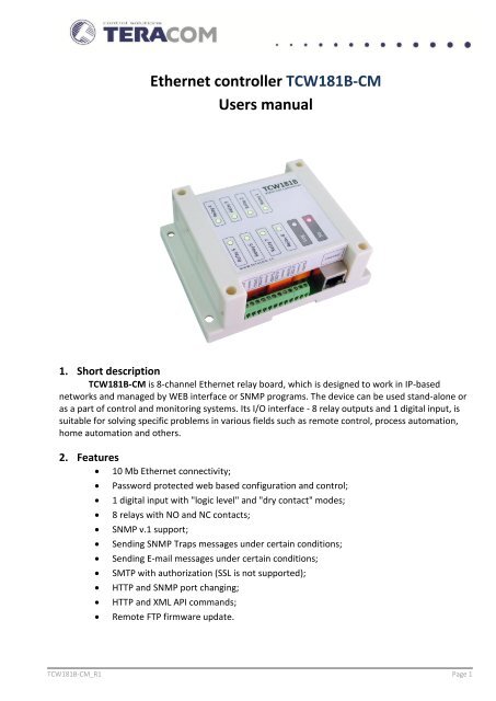
Ethernet controller TCW181B-CM Users manual - Teracom
Ethernet controller TCW181B-CM Users manual - Teracom

Create successful ePaper yourself
Turn your PDF publications into a flip-book with our unique Google optimized e-Paper software.
The <strong>controller</strong> supports only one active session – only one user can operate the device. Ifanother user tries to login, the following message appears: “Someone’s logged in”:The active session will be terminated automatically, if the current user stays inactive for 2 minutes.11.2 Monitoring pageAfter successful authorization, the “Monitoring” page appears:The “Monitoring” page provides information about the state of the relays and digital input.<strong>TCW181B</strong>-<strong>CM</strong>_R1 Page 5
Authentication details for WEB access to <strong>TCW181B</strong>-<strong>CM</strong>-<strong>CM</strong> can be set in the last section. Onlyone user is supported.11.4 SNMP Setup page<strong>TCW181B</strong>-<strong>CM</strong> supports SNMP v.1 that enables trap delivery to an SNMP managementapplication. This enables the device to be part of large monitoring and control networks. The possiblesettings for “SNMP” section are: SNMP Configuration – enable/disable SNMP; Read-Write community – performs client authentication; Read-Only community – performs client authentication; SNMP Traps – enable/disable SNMP trap messages; IP address – IP address of the receiving host Community string – performs client authenticationTrap Interval - time interval in seconds for SNMP trap messages;Max. Traps number – maximum number of SNMP trap messages sent, if trap condition ispresentSNMP traps are sent if: event occurs (status change) on Digital Input; restart condition.<strong>TCW181B</strong>-<strong>CM</strong>_R1 Page 7
11.5 I/O Setup pageThe following parameters can be set for the relays: Description – brief description of the output, maximum 10 characters can be used; Pulse Duration – time for relay activation when "Pulse" button on "Monitoring" page ispressed. This setting applies to all 8 relays.Every change on digital input can mange e-mail sending. Following parameters must be set: Mail to – e-mail address of recipient; Subject – e-mail subject; Message – e-mail body.Important! It is necessary to set SMTP server settings on "Network Setup" page, to successfullysend e-mail messages.In the example above, if an event occurs (closing contact) the <strong>controller</strong> will send e-mail messageto info@teracom.cc with subject "input alarm" and body "door open".Automatic monitoring page refresh interval can be set from 1 to 253 second. If 0 is chosen - noautomatic refresh.<strong>TCW181B</strong>-<strong>CM</strong>_R1 Page 8
12. Remote control application exampleThe controlled device is connected in series with the relay contacts. User can operate<strong>TCW181B</strong>-<strong>CM</strong> using either WEB browser or SNMP application. The relays can be managedindependently of each other.The above example is included solely for illustrative purposes. Because of the many variablesand requirements associated with any particular installation, <strong>Teracom</strong> Ltd. cannot assumeresponsibility or liability for actual use based on the example.13. Control and monitoring using SNMP<strong>TCW181B</strong>-<strong>CM</strong> can be configured and monitored through SNMP (Simple NetworkManagement Protocol). This could be done using every SNMPv.1 compatible program.Parametersthat can be changed, are grouped according to their functions in the tables below. To obtain a validOID number it is necessary to replace the “x” symbol with the ”1.3.6.1.4.1.38783”. To save thechanges configurationSaved (OID x.6.0) should be set to "1".13.1 ProductOID Name Access Description Syntaxx.1.1.0 name read-only Device name Stringx.1.2.0 version read-only Software version Stringx.1.3.0 date read-only Release date String13.2 SNMP SetupOID Name Access Description Syntaxx.2.1.0 trapEnabled read-write TRAP messages enable/disable INTEGER { no(0), yes(1) }x.2.2.0 trapReceiverIPAddress read-write TRAP messages receiver address IpAddressx.2.3.0 trapCommunity read-write TRAP community String (SIZE (0..13))<strong>TCW181B</strong>-<strong>CM</strong>_R1 Page 9
13.3 Monitor and controlOID Name Access Description Syntaxx.3.1.0 digitalInput read-only Digital input state INTEGER { closed(0), open(1) }x.3.2.0 relay1 read-write Relay 1 state INTEGER { off(0), on(1) }x.3.3.0 relay2 read-write Relay 2 state INTEGER { off(0), on(1) }x.3.4.0 relay3 read-write Relay 3 state INTEGER { off(0), on(1) }x.3.5.0 relay4 read-write Relay 4 state INTEGER { off(0), on(1) }x.3.6.0 relay5 read-write Relay 5 state INTEGER { off(0), on(1) }x.3.7.0 relay6 read-write Relay 6 state INTEGER { off(0), on(1) }x.3.8.0 relay7 read-write Relay 7 state INTEGER { off(0), on(1) }x.3.9.0 relay8 read-write Relay 8 state INTEGER { off(0), on(1) }x.3.10.0 pulse1 read-write Relay 1 pulse state INTEGER (0..255)x.3.11.0 pulse2 read-write Relay 2 pulse state INTEGER (0..255)x.3.12.0 pulse3 read-write Relay 3 pulse state INTEGER (0..255)x.3.13.0 pulse4 read-write Relay 4 pulse state INTEGER (0..255)x.3.14.0 pulse5 read-write Relay 5 pulse state INTEGER (0..255)x.3.15.0 pulse6 read-write Relay 6 pulse state IINTEGER (0..255)x.3.16.0 pulse7 read-write Relay 7 pulse state INTEGER (0..255)x.3.17.0 pulse8 read-write Relay 8 pulse state INTEGER (0..255)x.3.18.0 allOn read-write Set all relays On INTEGER (0..255)x.3.19.0 allOff read-write Set all relays Off INTEGER (0..255)x.3.20.0 allPulse read-write Pulse all relays INTEGER (0..255)13.4 NetworkOID Name Access Description Syntaxx.4.1.0 deviceIPAddress read-write Device IP address IpAddressx.4.2.0 subnetMask read-write Subnet Mask IpAddressx.4.3.0 gateway read-write Gateway IpAddressx.4.4.0 deviceMACAddress read-write Device MAC Address OCTET STRING (SIZE(6))x.4.5.0 dhcpConfig read-write DHCP ON/OFF INTEGER { off(0), on(1) }13.5 I/O SetupOID Name Access Description Syntaxx.5.1.0 relayPulseDuration read-write Global Pulse duration INTEGER (1..253)x.5.2.0 relay1description read-write Relay 1 description String (SIZE (0..11))x.5.3.0 relay2description read-write Relay 2 description String (SIZE (0..11))x.5.4.0 relay3description read-write Relay 3 description String (SIZE (0..11))x.5.5.0 relay4description read-write Relay 4 description String (SIZE (0..11))x.5.6.0 relay5description read-write Relay 5 description String (SIZE (0..11))x.5.7.0 relay6description read-write Relay 6 description String (SIZE (0..11))x.5.8.0 relay7description read-write Relay 7 description String (SIZE (0..11))x.5.9.0 relay8description read-write Relay 8 description String (SIZE (0..11))x.5.10.0 digitalInputAction read-write Digital Input Action conditionx.5.11.0 digitalInputTo read-writeDigital Input event receiver's e-mailaddressINTEGER { noAction(0),mailIfOpenToClosed(1),mailIfClosedToOpen(2) }String (SIZE (0..38))x.5.12.0 digitalInputSubject read-write Digital Input event e-mail's subject String (SIZE (0..11))x.5.13.0 digitalInputBody read-write Digital Input event e-mail's body String (SIZE (0..22))<strong>TCW181B</strong>-<strong>CM</strong>_R1 Page 10
x.6.0 configurationSaved read-writeConfiguration save statusSAVED/UNSAVEDINTEGER { unsaved(0), saved(1) }x.7.0 restartDevice read-write Restart Device INTEGER { cancel(0), restart(1) }14. XML and HTTP API commandsXML is often preferred choice when it comes to M2M communication and system integration.The monitored values are transmitted in status.xml file that can be easily processed by softwareapplications.Below is the structure of the XML file, which is located at: http://device.ip.address/status.xml:<strong>TCW181B</strong>-<strong>CM</strong>tcw181-cmv1.01OPENONOFFONOFFONOFFONOFFThe relay outputs can be controlled by sending HTTP commands:Device TypeFirmware versionDigital input stateRelay 1 stateRelay 2 stateRelay 3 stateRelay 4 stateRelay 5 stateRelay 6 stateRelay 7 stateRelay 8 stateCommandhttp://device.ip.address/?rX=1http://device.ip.address/?rX=0http://device.ip.address/?tgX=1http://device.ip.address/?plX=1http://your.ip.address/?rX=1&rY=1http://your.ip.address/?rX=0&rY=0DescriptionTurn Relay X ONTurn Relay X OFFToggle Relay X statePulse Relay XTurn both relays X and Y ONTurn both relays X and Y OFFNote: X and Y are the number of the corresponding relay output (1 to 8)15. Factory default settings<strong>TCW181B</strong>-<strong>CM</strong> can be restored to its original factory default settings, following the stepsbelow:Turn off the power supply;Press and hold the RESET button then turn on the power supply;The LED’s STS and LOG will flash 14 times, after that they will turn on. In this moment theRESET button should be released.<strong>TCW181B</strong>-<strong>CM</strong>_R1 Page 11
The factory default settings are:User Name (Admin)adminPassword (Admin)adminIP Address 192.168.1.2Subnet Mask 255.255.255.0Default Gateway 192.168.1.1SNMPConfigurationdisabledreadCommunitypublicwriteCommunityprivate16. Firmware update<strong>TCW181B</strong>-<strong>CM</strong> supports remote firmware update. To update the device follow the steps below:- Download the TCW1XX_Update_Tool program from www.teracom.cc;- Download the latest firmware version file (*.cod) from www.teracom.cc;- Start the program and update the firmware.Attention! Don’t turn off the power supply during the update. Turning off the power supply willdamage the device.Rev. 1 – September 2012Appendix A<strong>TCW181B</strong>-<strong>CM</strong>_R1 Page 12
Fig.1Fig.2<strong>TCW181B</strong>-<strong>CM</strong>_R1 Page 13


![User Manual [ver 4.00] - KOUKAAM, a.s.](https://img.yumpu.com/34554266/1/184x260/user-manual-ver-400-koukaam-as.jpg?quality=85)