
You also want an ePaper? Increase the reach of your titles
YUMPU automatically turns print PDFs into web optimized ePapers that Google loves.
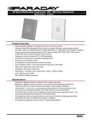
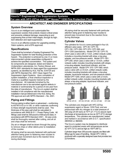
Sinorix TM Engineered Fire Suppression SystemsFor use with HFC-227ea and 3M TM Novec TM 1230 Fire Protection FluidARCHITECT AND ENGINEER SPECIFICATIONSSystem OverviewSinorix is an intelligent and customizable firesuppressionsolution that protects mission-critical areasand prevents collateral damage; responding to andsuppressing fires at their initial stages, through its hightechdetection and rapid suppression.Sinorix is an effective solution for upgrading existingHalon systems, and is EPA approved.SpecificationsThere shall be furnished a Faraday Engineered FireSuppression System for total flooding protection of thehazard. The protection is achieved by one (1) or moreinterconnected cylinder assemblies configured toachieve the specified concentration. The system andits components are designed, tested and listed toUnderwriters Laboratories, Inc; Factory Mutual, andNFPA 2001 standards for clean-agent fire suppressionsystems, as identified by UL File No. EX4724 andwith NFPA Standard No. 2001 Clean Agent FireSuppression Agent Systems. Upon completion ofsystem installation, a final checkout inspection ismade by a qualified inspector trained by themanufacturer. All materials furnished by themanufacturer are to be warranted against defects inmaterial or workmanship for a period of one year fromthe date of manufacture. The Sinorix system shall beinstalled in full compliance with the manufacturers’installation manual referenced in the UL listing, theFM approval and with NFPA Standard ─ No. 2001.All piping shall be securely fastened with particularattention being given to fastening near nozzles toprevent pipe movement due to the reaction forceduring discharge.Cylinder ValvesThe cylinders for Sinorix come packaged in four (4)different valve sizes: CPY-35 / CPY-70;CPY-150 / CPY-250; CPY-375 / CPY-560, andCPY-1200 (standalone). Model CPY-35 / CPY-70,which uses a valve with a 1-inch, unified victaulic outlet,includes a mounting bracket with strap; a top-plugadapter, and low-pressure switch. Model CPY-150 /CPY-250, which uses a valve with a 1.5-inch, unifiedvictaulic outlet, includes mounting brackets with straps;a top-plug adapter; liquid-level indicator, and lowpressureswitch. Model CPY 375 / CPY-560; whichuses a valve with a 2.5-inch, unified victaulic outlet,includes mounting brackets with straps; a top-plugadapter, liquid-level indicator, and low-pressure switch.Model CPY-1200, which uses a valve with a 4-inch,unified victaulic outlet, includes mounting brackets withstraps; a top-plug adapter; liquid-level indicator, andlow-pressure switch.Piping and FittingsFerrous piping is either black or galvanized ─ conformingto ASTM A-53 or A-106, or other materials confirmingto these strength requirements shall be used. Thethickness of the pipe wall shall be calculated inaccordance with ANSI B-31.1, Power Piping Code. Allfittings used shall be 300-pound or 600-pound class, inaccordance with NFPA Standard 2001. All pipe endsshall be thoroughly reamed after cutting, and all oiland chips shall be removed.Dry air or nitrogen shall be blown through the pipingto remove chips or other debris prior to installationof the nozzles.All piping shall be securely fastened with particularattention being given to fastening near nozzles toprevent pipe movement due to the reaction forceduring discharge.CPY-35 / CPY-70 CPY-150 / CPY-250 CPY-375 / CPY-560 CPY-1200The cylinders are charged with HFC-227easuppression agent or Novec 1230 Fluid, and arepressurized with dry nitrogen to a total pressure of360 psig (24.84 bars) at 70°F (21.1°C) to assure rapiddischarge at temperatures as low as 32°F (0°C) storagetemperature. The cylinders are manufactured, rested,and marked in accordance with D.O.T. specification4BW500 or 4BA500.The Sinorix system may be designed to distributeagent to protected areas with temperatures as lowas 10°F (12°C) and as high as 150°F (66°C).Cylinders larger than 250-pounds capacity are fitted withlifting lugs for ease of handling. Model CPY-1200 isproduced with a specially designed base that provides two(2) functions:<strong>9500</strong>
Pressure-Operated Switch ─(continued)Pressure-Actuated Control HeadEngineered (Pneumatic & Manual Actuation)The pressure-actuated head (Model CPY-PAS) allows forpneumatic pressure actuation of Sinorix cylinders.Model CPY-PAS is to be mounted directly on the topplugadapter assembly.Pressure-OperatedSwitchMaster / SlaveConfiguration HardwareThe purpose of the flex hose is to connect cylindersinto a master-slave configuration, where the mastercylinder (with releasing solenoid) shall supply pressurerelease up to seven (7) extra cylinders, depending onvalve size.¼” Flexible BraidedHosesHoses are fitted with swivel nuts for connection to the1/8-inch port marked ‘M’ on the master cylinder and to1/4-inch tees on pressure actuators on slave cylinders.The tees used with flexible hoses are fitted with1/8-inch N.P.T. male, for connection to pressureactuators. The hoses are furnished in three (3) lengths tosuit all cylinder sizes: 35 lbs. through 1200 lbs. Tosimplify installation and ease servicing of cylinders,1/4-inch flexible hose can be used in place of 1/4-inchcopper tubing, therefore eliminating the need to flaretubing.Flexible & Wire-Braid-ReinforcedDischarge HosesThe flexible and wire-braid discharge hoses are usedto facilitate connections between cylinder valves andsystem manifolding (or piping.) The flexible and wirebraiddischarge hoses minimize the effects ofvariations in the height of cylinder valve outlets, due todimension tolerances necessary in cylindermanufacture and floor irregularities. Flexible and wirebraiddischarge hoses are provided in 1, 1-1/2, 2-1/2and 4-inch sizes.The pressure from port marked ‘M’ on the cylinder valveis self-venting to prevent accidental system discharge inthe event of a gradual build up of pressure in a pilotline.Lever-ActuatedLocal Manual ReleaseThe Local Manual Control Head is equipped with anoperating lever for manual actuation of Sinorixcylinders.The Local Manual Control Head is installed on top ofcylinder valve, and is secured in a closed position by asafety pull pin. When the safety pull-pin is removed, thelever can be manually pushed down to the openposition. After the lever is pressed down, the valve onwhich it is installed will activate. The lever will remainlocked until manually reset. The lever-operated controlhead is self-venting.Room PlacardsPressure-ActuatedControl HeadLocal Manual Control HeadThere are (8) eight different types of caution and noticeRoom Placards for Sinorix Fire Suppression Systems.Each placard is made in Gravoply1 Engraving Stockor equivalent.Flex HosesWire-Braided Reinforced HosesEach placard is red stock with engraved, white lettering.Font size for each placard is approximate to what is shownin this document. Each placard comes prepared withdouble-sided, fixed adhesive on the reverse. Eachplacard shall be wall mounted at eye level.
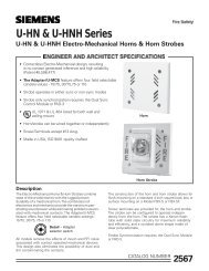
Abort StationModel AW-1 Abort Station employs a momentary, normallyclosed contact ‘dead-man type’ push-button switch, which –while held in – prevents discharge of the clean agent. Uponrelease of the push button, the Sinorix Engineered Fire-Suppression System will follow the sequence of events asprogrammed in the releasing panel, ultimately resulting in therelease of the Sinorix agent.Abort StationModel AW-1 consists of a momentary contact switch witha large red ‘mushroom head’ for ease of operation. It ismounted on a steel plate. Screw type terminals areprovided for connection to the agent release circuit. Theentire assembly mounts on a standard 2-1/2" deep, (2)two-gang electrical box.Manual Release StationThe basic, standard model for the manual release stationis the double-action Model MH-501, which contains one(1) normally open contact. Model MH-501 is intended foruse with <strong>Siemens</strong> ─ Fire Safety low-voltage systems, buthas a rating of 120VAC for connection to other systems.Manual Release StationThe Manual Releasing Station (MH-501) is constructed ofdurable, molded polycarbonate material, matte-finished inred with raised lettering in white. The housing incorporatesa ‘push-in tab,’ which must first be operated, permittingaccess to the pull-down lever, which ─ when operated ─locks in position after releasing a spring-loaded contactswitch. Restoring the system to normal can only beaccomplished by opening the cover of the hinged housingwith a reset key and then closing and locking the cover.The Manual Release Station is constructed with a moldedhousing, fitted with a pull-down lever and a ‘push-in’ tab.Since the manual release station is ‘dual-action type,’ it isnecessary to first operate the ‘push-in tab’ in order toprovide access to the pull-down lever, which – whenoperated – locks in position after releasing a spring-loadedcontact switch to effect actuation of the release circuit.The body of the control is hinged to a back-plate assemblyto which it is locked with a socket head screw.Resetting the control after operation requires opening thecontrol momentarily, and then locking the body tothe back plate. Provision shall be made for surface orsemi-flush mounting to conduit boxes.Main / Reserve Selector SwitchThe main / reserve selector switch is a means fortransferring the electrical supply from the main cylinderto the reserve cylinder. The switch is mounted on asteel cover plate. Screw-type terminals shall beprovided. The entire assembly is capable for mountingon a standard 2-1/2"-deep, two-gang electrical box.Main / Reserve Selector SwitchA flapper check valve is used when (2) two equivalentcylinder valve assemblies are configured with (1) onecommon discharge pipe ─ via a ‘Main / Reserve’ orManifold configuration ─ in the event one or morecylinder valve assemblies are removed for servicing.Flapper Check ValvesEach flapper check valve serves as a ‘stop gap,’preventing loss of agent in the event any of the agentstoragecylinder valves are not connected to themanifold at the time of agent discharge. Additionallycheck valves put a stop to agent back-flow in‘Main / Reserve’ or ‘Manifold’ configuration.Flapper Check ValveFlapper check valves offer a lower friction co-efficientthan legacy valves, and are currently available in 2-inch, 3-inch and 4-inch sizes.Sinorix 1230 AgentSinorix 1230 is an automatic, waterless suppressionagent used to protect vital assets and artifacts. Theclean agent uses Novec 1230 Fluid (Model CPY-1230),which suppresses fire at low concentrations, and is safefor sensitive electronic equipment because it iselectrically non-conductive.Model CPY-1230 is recommended for conditions whereclean-up of other means of extinguishing presents alogistical issue; an electrically non-conductive mediumis needed, or storage efficiency is critical.<strong>Siemens</strong> Industry, Inc. ─ <strong>Building</strong> <strong>Technologies</strong> Div.8 Fernwood Road • Florham Park, NJ 07932Tel: (973) 593-2600 • Fax: (908) 547-6877Web: www.FaradayFireAlarms.comWARNING - The information contained in this data-sheet document is intended only as a summary, and issubject to change without notice. The devices described here have specific instruction sheets that covervarious technical, limitation and liability information. Copies of these instruction sheets and the GeneralProduct Warning and Limitations document, which also contains important information, are providedwith the product and, are available from the Manufacturer.Information contained in these documents should be consulted before specifying or using the product.For further information or assistance concerning particular problems contact the Manufacturer.<strong>Building</strong> <strong>Technologies</strong> DivisionSII ─ Fire Safety[Printed in U.S.A ]April 2011 – Supersedes sheet dated 1/2010(Rev. 2)