Instruction Manual (pdf) - Dover Flexo Electronics, Inc
Instruction Manual (pdf) - Dover Flexo Electronics, Inc
Instruction Manual (pdf) - Dover Flexo Electronics, Inc

You also want an ePaper? Increase the reach of your titles
YUMPU automatically turns print PDFs into web optimized ePapers that Google loves.
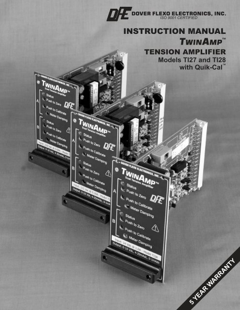
DOVER FLEXO ELECTRONICS, INC.ISO 9001 CERTIFIEDINSTRUCTION MANUALTAWIN MP TENSION AMPLIFIERModels TI27 and TI28with Quik-Cal 5 YEAR WARRANTY
NEW!QUIK-CAL PUSHBUTTON ZERO-SET AND CALIBRATION-SETThe TwinAmp tension amplifiers are built with a labor-saving technology called Quik-Cal!They do not have potentiometers for zero and calibration settings. Instead, they havepushbuttons. Push the button once, hold for one second, and you are done!No tension display is needed. No screwdriver is needed. No second-person is needed.ZERO SETThe weight of the transducer roll produces an output that is not caused by web tension.This is not desirable because it is not a tension measurement. To set the output of theindicator to zero when there is no tension, just press the ZERO button and hold for onesecond.You can even eliminate the need to press the ZERO button! The indicator canautomatically set the output to zero when power is turned on. Just change a jumper settingon the circuit board.CAL SETThe weight you select for calibration determines the full-scale tension signal output. Theindicator automatically multiplies the weight by the built-in calibration ratio to calculate fulloutput.The calibration ratio is the ratio of the calibration weight to the tension at full output.The standard calibration ratio is 1:10, or 10%. For example, if you hang a 15 lb. weight andpush the CAL button, the indicator will produce full output at 150 lbs. tension.A calibration ratio of 25% is available for low tensions. (This is selected by jumpers on thecircuit board). If you use of a 15 lb. calibration weight, this will produce full output at 60 lbs.tension. The A and B amps can have different calibration ratio values.STABILITY is another benefit of this technology. The zero and calibration settings are storeddigitally, so there is no drift over time and temperature variations as there can be withpotentiometers.Read Section 3.3 for details.-a-
-b-
TABLE OF CONTENTSSECTION ONE PRODUCT DESCRIPTION1.1 General Description ........................................ 11.2 Front View of TwinAmp .................................... 11.3 Specifications ............................................. 21.4 Environmental Conditions ................................... 21.5 Standard Features ......................................... 31.6 Options .................................................. 31.7 Accessories .............................................. 4SECTION TWO INSTALLATION2.1 Dimensions............................................... 52.2 Selection of Mounting Location ............................... 72.3 Safety & EMC Requirements ................................. 72.4 Installation <strong>Instruction</strong>s...................................... 82.5 Transducer Voltage Selection ................................ 82.6 Tension Meter Output Selection............................... 92.7 Standard Electrical Connections .............................. 9SECTION THREE CALIBRATION AND SETUP3.1 Preparation ............................................... 113.2 Mechanically Zero the Tension Meter .......................... 113.3 Calibrate the Output for Accuracy ............................. 11SECTION FOUR OPERATING INSTRUCTIONS ............................... 14SECTION FIVE CARE AND MAINTENANCE ................................. 15SECTION SIX TROUBLESHOOTING GUIDE ............................... 16SECTION SEVEN REPLACEMENT PARTS .................................... 17APPENDICESAPPENDIX: A Location of Jumpers and Adjustments (Figure 12) ................ 18B Electrical connections (Figure 13) ............................. 19C Transducer Electrical Connections (Figure 13-17) ............... 20D Typical Tensions of Various Materials .......................... 24E Environmental Terms ...................................... 25Terms and Conditions of Sale and Shipment .................... 26Index .................................................... 27
LIST OF ILLUSTRATIONSFIGUREPAGE1 Front View of TwinAmp ..................................... 12 Ti27/Ti28 Unit Dimensions and Views .......................... 53 Accessory Plug-in Card Adapter Dimensions .................... 64 Accessory Tension Meter Dimensions.......................... 65 Accessory Tension Meter Enclosure Dimensions ................. 76 Transducer Voltage Jumpers ................................. 97 Tension Meter Output Jumpers ............................... 98 Standard Electrical Connections .............................. 109 TwinAmp Showing Cal, Zero, and Jumper Locations .............. 1110 Web Path ................................................ 1211 Replacement Part Numbers.................................. 1712 TwinAmp PC Board Showing Component Locations .............. 1813 Standard Electrical Connections .............................. 1914 Models C, RS, & F Transducer Wiring .......................... 2015 RFA Transducer Wiring ..................................... 2116 TR & NW Transducer Wiring ................................. 2217 LT Transducer Wiring....................................... 23
SECTION 1PRODUCT DESCRIPTION1.1 GENERAL DESCRIPTIONThe TwinAmp dual tension amplifiers are designed to provide two isolated interfaces in one packagebetween any type of DFE tension transducers and variable speed drive systems, computers, tension recorders, orother devices for tension control and display purposes. Outputs from each amplifierr are 0-10Vdc, 4-20mA, and0-1mA. The 0-1mA outputs to allow the user to connect analog or digital meters to indicate operating tension.The TwinAmp contains two independent tension amplifier circuits on one card. Each has its own calibrationadjustments and outputs. The card is an IEC/ANSI/IEEE type 2 plug-in unit for installation in a standard size3U 19 inch rack. This plug-in feature allows for easy field installation and servicing.Quik-Cal pushbutton zero and calibration comes standard..The only difference between the Ti27 and the Ti28 versions is their power input requirements. The Ti27operates on 115Vac 60Hz (230Vac 50Hz optional) and the Ti28 operates on 24Vdc. WARNING: The isolated output is designed to prevent ground loops and noise. It is not intended orapproved for safety isolation of hazardous voltages. Do not install unit where the isolated circuit and chassisground are more than 40Vpk differential. WARNING: Ti27 models are designed for single phase AC operation only. Do not connect them acrossthree phase lines or to three phase circuits, to prevent product damage and potential hazard.1.2 FRONT VIEW OF TWINAMP Figure 1 - FRONT VIEW OF TWINAMP 1
1.3 SPECIFICATIONSPower Input: Voltage .............. Ti27 = 120 Vac/60Hz +/- 10%, (230Vac/50Hz optional)Single Phase AC operation only............... Ti28 = 24 Vdc +/- 10%.Typical Current .............. Ti27 = 120 Vac, 60 Hz = 0.105 Amp AC.............. 230 Vac, 50 Hz = 0.054 Amp AC.............. Ti28 = 0.10 Amp dc.Maximum Current: .............. Ti27 = 120/230 Vac = 0.160/0.080 Amp AC.............. Ti28 = 1.0 A dcTension Signal Outputs(3 outputs per channel): .............. 1. 0 to +10Vdc, Isolated from input power and transducercircuits............... • 0 to +10Vdc capable of over-range, -15% to 120%of full scale (-1.5Vdc to 12Vdc), to indicate overrangeor error conditions............... • 0 to +10Vdc max loading is 5mA. This requires a2000 Ohm or greater input resistance for equipmentconnected to this output.2. 4-20mA capable of over-range, -15% to 120% of fullscale (1.6mA to 23mA), to indicate over-range or errorconditions. 4-20mA maximum loop resistance is 500Ohms.3. 0 to 1mA meter output with adjustable damping foroptional tension meter.Weight: .............. Ti27 = 1.25 lbs (0.57 kg), Ti28 = 1.0 lbs (0.45 kg)Transducer Signal Input: .............. 500 mVdc maximum at rated load per pair (1 Vdc with(per channel) XRE option)Transducer Excitation: .............. 5Vdc (10Vdc for the XRE option) jumper selectable.(per channel)Accuracy: .............. Max error of 1% over temperature range. 0.1% Typical.Zero (Tare) Range: .............. Minimum 95% of transducer rating.Calibration Range: .............. Minimum 50 : 1.Ambient Temperature Range: .............. 32°F to 104°F (0°C to 40°C).Accessory tension meter types: .............. Analog:1mA, 49 ohm movement, 3.5" (P/N: 722-1385),in enclosure (P/N: 723-2682) or.............. Digital:4 digit display, LED (P/N:723-2307), in enclosure(P/N:723-2660).Standard tension meter scales: .............. 0 to: 1, 5, 10, 25, 50, 100, 150, 250, 500, 1000.1.4 ENVIRONMENTAL CONDITIONS (Ref. Appendix E for further information)This section applies to equipment designed to be safe at least under the following conditions:• Indoor use.• Altitude up to 6500 ft (2000 meters).• Temperature range: 32° F to 104° F (0° C to 40° C).• Maximum relative humidity 95% over the temperature range (non-condensing).• Main supply voltage fluctuations not to exceed +/-10% of the nominal voltage.• Main supply transient overvoltages according to overvoltage category II of IEC 60364-4-443.• Pollution Degree 2 in accordance with EN61010-1:2001.2
1.5 STANDARD FEATURESSOME OF THESE FEATURES REQUIRE CONFIGURATION OR EXTERNAL WIRING. REFER TOSECTION 2.4 FOR INSTALLATION INSTRUCTIONS AND SECTION 2.7 FOR WIRING.• Quik-Cal push-button zero and calibration eliminates pot adjustments to make calibrating simple and fast.• 2 separate sets of 0 to +10V and 4 to 20mA Isolated Tension Outputs. Proportional to tension. Used asan input to a controller or instrumentation system. Both are isolated outputs standard. See Section 3.1 forinstallation and adjustment. WARNING: The isolated output is designed to prevent ground loops and noise. It is not intended orapproved for safety isolation of hazardous voltages. Do not install unit where isolated circuit and chassis groundare more than 40Vpk differential.• Two 0-1mA Tension Outputs. A separate output on each amplifier with adjustable damping, used fordriving an optional analog tension meter.• Adjustable Meter Damping. Used to adjust the responsiveness of the optional analog tension meter. Doesnot affect the 0-10V/4-20mA output.• Power Voltage Selection. The Ti27 version is designed to operate at either 115Vac (standard) or 230Vac(optional factory modification). The Ti28 operates on 24Vdc.• Easily serviceable. The unit can easily be removed from the rack mount.• Standard size. Fits in standard size 3U 19 inch rack, up to 6 units to a rack.• Flexible Operation. Features can be tailored for each application.• Economical. Provides many important features at a reasonable price.• Short Circuit Protection. Unit automatically protects transducer excitation and tension output from shortcircuits or excessive loading. If a short circuit is detected, the unit will safely shut that portion of the circuitoff until the fault is cleared. Unit automatically recovers when the fault is removed (Power may have to becycled off for 15 seconds in extreme cases).1.6 OPTIONSSOME OF THESE OPTIONAL FEATURES REQUIRE CONFIGURATION OR EXTERNAL WIRING.REFER TO SECTION 2.4 FOR INSTALLATION INSTRUCTIONS AND SECTION 2.7 FOR WIRING.• 0-100 µA Tension Output (100M). Alternate to the standard 0-1mA meter output. Jumper selectable.• 230 Volt Input (230). 230Volt, 50 Hz AC power input. Ti27 only. Set at factory. WARNING: Ti27 models are designed for single phase AC operation only. Do not connect them acrossthree phase lines or to three phase circuits, to prevent product damage and potential hazard.• 25% Calibration Weight (25CW). Used when 25% of full scale calibration weight is desired instead of thestandard 10% calibration weight. Jumper selected between 10% and 25%.• Auto Zero (AZ). Unit will auto zero the output on each power up. Jumper selected on or off for each amp.• Extended Range (XRE). 10 Vdc excitation for Extended Range transducers. Allows measurement of muchlower tension than usual. Transducers must also have the XR option. Jumper selected between 5Vdc and10Vdc for each amplifier.3
1.7 ACCESSORIES• Remote Tension Meter. Analog, 1 mA (DFE P/N: 722-1385) supplied as a single unit. Must be installed byuser. This meter is also available in its own enclosure (DFE P/N: 723-2682).• Nonstandard Meter Scale. Any other meter scale than standard ones offered by DFE. See Specificationsfor standard scales. Applies to remote tension meter listed above.• Remote Digital Tension Meter. 4 digit, 0-1 mA (DFE P/N: 723-2307) supplied as a single unit withoutenclosure, or with enclosure (DFE P/N: 723-2660). Must be installed and powered (+24V) by user.• Type 5 Plug-in Adapter. Plug the Ti27/28 into this adapter instead of a 19 inch rack. Terminal strips forhard-wired connections. Install the unit in your own enclosure (DFE P/N: 143-0000).4
SECTION 2INSTALLATION2.1 DIMENSIONS inches (mm)Figure 2 - Ti27 and Ti28 UNIT DIMENSIONS and VIEWS5
Figure 3 - ACCESSORY PLUG-IN CARD ADAPTER DIMENSIONSFigure 4 - ACCESSORY TENSION METER DIMENSIONS6
Figure 5 - ACCESSORY TENSION METER ENCLOSURE DIMENSIONS2.2 SELECTION OF MOUNTING LOCATIONThe TwinAmp Ti27 or Ti28 is plugged into a standard 19 inch rack having an opening 3U high by 14HP wide.The optional plug-in adapter may also be used.Note: The Ti27 and Ti28 have been designed to meet the EMC directive, and for that compliance, the unit mustbe installed in a shielded enclosure and used with shielded cables (DFE cables are shielded).2.3 SAFETY AND EMC REQUIREMENTS: WARNING: If this equipment is not connected or operated in the manner specified, the operating safety ofthis unit or of connected equipment cannot be guaranteed. WARNING: The isolated output is designed to prevent ground loops and noise. It is not intended orapproved for safety isolation of hazardous voltages. Do not install unit where isolated circuit and chassis groundare more than 40Vpk differential. WARNING: Ti27 and Ti28 models require a full enclosure to protect against shock hazard.! IMPORTANT: For safety reasons, it is necessary to use appropriate wiring for your line voltage connectionsand for safety grounding. Make your ground connection between a reliable earth ground and the safety ground ofyour indicator using a wire with a gauge of at least 16 AWG (or a cross-sectional area of at least 1mm 2 ) andinsulation rating of at least 600V. Make your AC line voltage connections with wire gauge of at least 16 AWG(or a cross-sectional area of at least 1mm 2 ) and insulation rating of at least 600V for each conductor. Secure thiswiring to prevent inadvertent removal or strain on the input terminal.An external switch or circuit breaker is required for power disconnection on the Ti27, and it is recommendedthat this switch or circuit breaker be near the equipment, and be well labeled.7
In addition, to meet the EMC Directive, a proper transducer installation, including shielded cables must alsobe used. The following is a list of cables available from DFE which meet this requirement721-0084 CN 3-conductor cable for type C, RS, THN, and UPB transducers. Use 2 cables, 1 cable pertransducer.721-0964 CN 6-conductor cable for type RFA, LT, VNW, NW, and TR transducers.Other cables manufactured by DFE also meet this requirement. Contact DFE for more information.In addition to the transducer cable shielding, a shielded meter cable (DFE P/N: 721-0967, 15 ft., other lengthsavailable) and meter in enclosure (DFE P/N: 723-1453) are required to meet the EMC directive when anaccessory meter is used.Cable shielding must be attached to the SHIELD connection on the terminal block, or to an appropriatelygrounded enclosure. If you wish to assemble your own cables, contact DFE for assembly instructions.! IMPORTANT: The DFE Model Ti28 you have purchased has been designed to meet the European Union'sLow Voltage Directive and EMC Directive only when installation is done correctly. To meet the EMCDirective, a proper transducer installation, including shielded cables must be used. The following is a list ofcables available from DFE which meet this requirement:721-0084 CN 3-conductor cable for type C, RS, THN, and UPB transducers. Use 2 cables, 1 cable pertransducer.721-0964 CN 6-conductor cable for type RFA, LT, VNW, NW, and TR transducers.Other cables manufactured by DFE also meet this requirement. Contact DFE for more information.In addition to the transducer cable shielding, a shielded meter cable (DFE P/N: 721-0967, 15 ft., other lengthsavailable) and analog meter in enclosure (DFE P/N: 723-2682) are required to meet the EMC directive when anaccessory meter is used.Cable shielding must be attached to the SHIELD connection on the terminal block, or to an appropriatelygrounded enclosure.2.4 INSTALLATION INSTRUCTIONSThe TwinAmp is plugged into a standard 19 inch rack having an opening 3U high by 14HP wide. The optionalplug-in adapter may also be used.Note: The TwinAmp has been tested to meet the EMC directive, and for that compliance, the unit must beinstalled in a shielded enclosure and used with shielded cables (DFE cables are shielded).2.5 TRANSDUCER VOLTAGE SELECTION (Refer to Figure 6)The tension transducers are excited by either the standard 5 Vdc, or 10 Vdc with the Extended Range optionor LT (low tension) transducer.!!CAUTION Do NOT use the 10 Vdc excitation unless the transducers are LT type transducers or have theextended range option! The TRANSDUCERS MAY BE DAMAGED!Set the Amplifier A transducer excitation jumpers as follows:5 Vdc - Jumper on JP1, pins 1-2. 10 Vdc (XRE) - Jumper on JP1, pins 2-3.The B Amp uses JP2 and may be set independent of the A Amp selection.8
Figure 6 - TRANSDUCER VOLTAGE JUMPERS2.6 TENSION METER OUTPUT SELECTIONSelect the 0-1mA current outputs by setting jumpers JP3 (Indicator A) and JP4 (Indicator B) to thedesired output. The unit ships from the factory set for 0-1mA meter output.Figure 7 - TENSION METER OUTPUT JUMPERS2.7 STANDARD ELECTRICAL CONNECTIONSKeep in mind that each channel of the TwinAmp (amplifier A or B) is designed to provide a 0-1mA dampedmeter output, and a 0-10V isolated and a 4-20mA isolated output. These outputs are not isolated from each otherwithin an Amplifier. All A amp outputs share an isolated common. All B amp outputs share a separate isolatedcommon. Connecting the 2 isolated commons will not cause problems in normal operation. Avoid connectingthem to Transducer Common which is not isolated. Also note that the 4-20mA A & B returns must be connectedto the correct pins. The 4-20mA will not function correctly if returned to another pin. See Fig 8 for connections.NOTE: If connecting outputs to Drive motor inputs, Avoid connecting A and B Amp Commons together. Pastissues have often been solved by isolating drives from all other electronics.9
2.7 ELECTRICAL CONNECTIONS continued........Connect Power to the Appropriate pins.Warning! Do not connect +24Vdc to Ti27 units. Likewise, Do not connect AC Voltage to Ti28 units.Make your wiring connections as follows:1. The insulation rating of all line voltage wiring must be at least 600V2. Keep line voltage wiring physically separated from signal wiring at the terminal block and at any other pointin the installation.3. Connect cable shields to Earth Ground.Figure 8 - STANDARD ELECTRICAL CONNECTIONS10
SECTION 3CALIBRATION and SETUP3.1 PREPARATION1. For each amplifier (channel), Amp A and Amp B, select an appropriate calibration weight. Remember that theweight determines the value of web tension that will produce full output from each amplifier. Example: a15 lb. weight will result in full output at 150 lbs. tension with the standard calibration ratio of 10%. (If theoptional cal. ratio of 25% is used, a calibration weight of 15 lbs. will result in a full output at 60 lbs. tensionfor example). A spring scale can also be used, but absolute accuracy may be reduced. Repeatability will notchange.2. Get a length of rope, wire, or cable of appropriate length. It must NOT be extensible (stretchy). This willcause inaccurate calibration.3. If you wish to use a calibration ratio of 25% for Amp A, locate jumper JP6 on the PCB and move it to the25% position.4. If you wish to use a calibration ratio of 25% for Amp B, locate jumper JP8 on the PCB and move it to the 25%position.3.2 MECHANICALLY ZERO THE TENSION METER(This step is necessary only if the optional analog tension meter(s) is/are to be used).Turn off power to the TwinAmp and observe whether the tension meter needle rests at 0. If not, turn theadjustment screw on the rear of the meter as required to set the meter needle at 0 on the scale. Note that the meteris sensitive to changes in mounting attitude. (Tilt from vertical meter face)3.3 CALIBRATE THE OUTPUT FOR ACCURACYFigure 9 - TWINAMP SHOWING CAL, ZERO, and JUMPER LOCATIONS11
1. ZERO: Ensure nothing is hanging on or pressing on the tension rolls (including the calibration rope). Pressthe ZERO A pushbutton on the unit front panel for at least 1 second. The unit will store the tension zero onesecond after the button is pressed. The unit will flash the green STATUS A LED (located above the ZERO Abutton) ONCE to indicate the zero has been stored. Release the button. The A outputs will produce 0Vdcand 4mA. The tension meter (if attached) will read zero.Press the ZERO B pushbutton on the unit front panel for at least 1 second. The unit will store the tensionzero one second after the button is pressed. The unit will flash the green STATUS B LED (located above theZERO B button) ONCE to indicate the zero has been stored. Release the button. The B outputs will produce0Vdc and 4mA. The tension B meter (if attached) will read zero.<strong>Manual</strong> re-zero can be performed at any time. Simply ensure nothing is touching the tension roller, andpress ZERO until the green LED (above the ZERO button) flashes once, then release. The zero setting isupdated, and the CALIBRATION is maintained.2. CALIBRATION: Fasten one end of the rope in the machine and thread the other end around the transducer rollin exactly the same path the web will take for the A amplifier. Be sure the rope does not pass around anydriven rolls, drag bars, or anything else that can affect tension. Ideally the rope should hit an idler rollimmediately before and after the tension sensing roll. It does not have to pass over any other rollers oncethese three are strung.1. Attach the weight to the free end of the rope as shown in Figure 10. The weight should not touchanything. Wait for the weight to stop swinging.Figure 10 - WEB PATH2. Press the CAL A pushbutton on the unit front panel for at least 1 second. The unit will store thecalibration information one second after the button is pressed. The unit will flash the green STATUS ALED (located above the ZERO A button) ONCE to indicate the calibration has been stored. The Aoutputs will read 1.0Vdc and 5.6mA (For 10% calibration percentage) or 2.5Vdc and 8mA (For 25%calibration percentage). The A meter will read 10% of full scale or 25% depending upon JP6 setting.3. Remove the weight and observe the A output. It should read 0Vdc or 4mA with nothing touching thetension sensing roller, and if steps 2.1 to 2.3 above were done correctly.4. Thread the rope around the Amp B transducer as detailed above.5. Attach the weight to the free end of the rope as shown in Figure 10. The weight should not touchanything. Wait for the weight to stop swinging.6. Press the CAL B pushbutton on the unit front panel for at least 1 second. The unit will store thecalibration information one second after the button is pressed. The unit will flash the green STATUS BLED (located above the ZERO B button) ONCE to indicate the calibration has been stored. The Boutputs will read 1.0Vdc and 5.6mA (For 10% calibration percentage) or 2.5Vdc and 8mA (For 25%calibration percentage). The B meter will read 10% of full scale or 25% depending upon JP6 setting.7. Remove the weight and observe the B output. It should read 0Vdc or 4mA with nothing touching thetension sensing roller, and if steps 2.4 to 2.6 above were done correctly.!CAUTION: Do NOT press ZERO or CAL pushbuttons while the web is running. The unit will storeZERO or CALIBRATION and the old settings will not be recovered. The only way to recoverCALIBRATION is to perform this procedure starting at step 1.12
3. METER DAMPING: If the optional analog meter is used, adjust the MTR DAMP potentiometer while themachine is running to minimize needle movement. Damping only affects the 0-1mA meter output and not the0-10Vdc or 4-20mA isolated outputs. (See Fig. 9). A and B Damping is set independently.4. AUTO-ZERO: If you want the unit to automatically re-zero every time power is applied, move jumper JP7 (Aamp) and/or JP9 (B amp) to pins 2-3 (Auto-Zero ON). The default is Auto-Zero OFF (JP7 Pins 1-2 and JP9pins 1-2). (See Fig. 9).!CAUTION: Auto-Zero must be used with care. If power can be cycled to the unit (for any reason) whilethe web is resting on the tension roller, Auto-Zero should NOT be activated. The unit will store the updatedtension input as the new zero on power up. This can damage the web as the actual tension would be higherthan reported by the unit.<strong>Manual</strong> re-zero can be performed at any time. Simply ensure nothing is touching the tension roller, andpress ZERO until the green LED (above the ZERO button) flashes once, then release. The zero setting isupdated, and the CALIBRATION is maintained.The output calibration is now complete.13
SECTION 4OPERATING INSTRUCTIONSYour TwinAmp dual tension amplifier will indicate tension in your system without any further operatorintervention. It is a good idea to make a check at roughly one month intervals to verify that no one has changedthe calibrations. See Section 3 for calibration and setup.14
SECTION 5CARE AND MAINTENANCEIt is not necessary to perform any type of maintenance on the TwinAmp. However, you may find itworthwhile to observe whether there is a buildup of dust, debris, or moisture on or near the unit after a period oftime. If so, you may consider putting the unit in a more appropriate location.15
SECTION 6TROUBLESHOOTING GUIDEMost problems are caused by incorrect installation and misapplication of the equipment. It is very important tobe sure these factors are correct before making any changes to calibration and jumper settings.The green status LEDs (located on the left edge of the board) indicate the operating status of the unit. Theyshould be on steady within one second of power application. The green status LED should not be flashingduring operation except when pressing ZERO or CALIBRATION pushbuttons (LED will flash once indicatingacceptance of ZERO or CAL). Continuous flashing is an indication of a problem - contact DFE technicalsupport if this condition is observed.If both green status LEDs are not lit when power is applied, check fuses on the TwinAmp. If they need to bereplaced, use the correct values listed below (all fuses 5mm x 20mm type):Ti27 (2 Fuses): 115V Operation = 160mA, 250V IEC Fast Acting (DFE P/N: 108-0082)230V Operation = 80mA, 250V IEC Fast Acting (DFE P/N: 108-0091)Ti28 (1 Fuse): 1A, 250V IEC Fast Acting (DFE P/N: 108-0097) WARNING: Equipment must be disconnected from HAZARDOUS LIVE voltage before changing thefuses. ( Removing the unit from the rack will fulfill this requirement) WARNING: Only replace fuses with the correct size, value, and speed rating. Use of non-certified fuses orfuses with incorrect ratings MAY CAUSE A SHOCK OR FIRE HAZARD.The test points on the circuit card can provide an indication of proper operation or problems if they exist.Typical voltages on the test points follow: (See Appendix A for test point locations).Voltmeter positive lead Voltmeter negative lead Typical VoltageTP1 TP20 15.5 Vdc (A)TP26 TP20 15.5Vdc (B)TP9 TP20 5Vdc (A)TP15 TP20 5Vdc (B)TP4 (+EXC A) TP20 5Vdc (STD), 10.1Vdc (XR)TP28 (+EXC B) TP20 5Vdc (STD), 10.1Vdc (XR)TP5 (Amp A) TP11 0-10Vdc output, changes depending ontension input and ZERO/CAL settings.TP27 (Amp B) TP22 0-10Vdc output, changes depending ontension input and ZERO/CAL settings.Some variation of the listed voltages should be expected. If any voltage deviation greater than 10% of typicalis measured, contact DFE technical support for assistance.NOTE: The unit must be plugged into a properly wired connector/rack to check these values. An extender cardcan be used in the rack. These tests should only be performed by qualified technical personnel following normalsafety procedures.If you have any problems with the functions on your TwinAmp Dual Tension Amplifier, please call TechnicalService at 603-332-6150 or Fax 603-332-3758. E-mail: techsupport@dfe.com.16
SECTION 7REPLACEMENT PARTSSee diagram below for separate components. WARNING: When replacing fuses, use only fuses with ratings as shown below. Failure to do this maycompromise personal safety and may create a fire hazard!1. 323-0943 Front Overlay - Ti27321-0953 Voltage Input Sticker - Specify Unit Voltage2. 108-0082 (2) Fuses, 160mA 250V for 115Vac - Ti273. 108-0091 (2) Fuses, 80mA 250V for 230Vac - Ti274. 108-0002 (1) Fuse, 1A, 250V for 24Vdc - Ti285. 108-0105 Fuse Covers - (2) for Ti27, (1) for Ti287. Accessory Tension Meters (not shown)722-1385 Analog Tension Meter,723-2682 Analog Tension Meter in enclosure,723-2307 Digital Tension Meter723-2660 Digital Tension Meter in enclosure721-0967 Shielded Meter Cable, 15 ft.8. 801-2336 <strong>Instruction</strong> <strong>Manual</strong> (not shown)Figure 11 - REPLACEMENT PART NUMBERS17
Appendix A:Locations of Jumpers and AdjustmentsFigure 12 - TWINAMP PC BOARD SHOWING COMPONENT LOCATIONS (Simplified for clarity)018
Appendix B:Electrical ConnectionsTWINAMP STANDARD CONNECTIONS:Make your wiring connections as follows:Warning! Do not connect +24Vdc to Ti27 units. Likewise, Do not connect AC Voltage to Ti28 units.1. The insulation rating of all line voltage wiring must be at least 600V.2. Keep line voltage wiring physically separated from signal wiring at the terminal block and at any other pointin the installation.3. Connect cable shields to earth ground.Figure 13 - STANDARD ELECTRICAL CONNECTIONS19
Appendix C:Transducer Electrical ConnectionsFigure 14 - MODELS C, RS, & F TRANSDUCER WIRING20
Figure 15 - RFA TRANSDUCER WIRING21
Figure 16 - TR & NW TRANSDUCER WIRING22
Figure 17 - LT TRANSDUCER WIRING23
Appendix D:Typical Tensions for Various MaterialsTYPICAL TENSIONS FOR WEB MATERIALSACETATE0.5 lb. per mil per inch of widthFOIL Aluminum 0.5 lb. per mil per inch of widthCopper 0.5 lb. "CELLOPHANENYLON0.75 lb. per mil per inch of width0.25 lb. per mil per inch of widthPAPER 15 lb * 0.4 lb. per inch of width20 lb 0.5 lb. "30 lb 0.75 lb. "40 lb 1.25 lb. "60 lb 2.0 lb. "80 lb 3.0 lb. "100 lb 4.0 lb. "* based on 3000 sq. ft. reamPAPERBOARD 8pt 3.0 lb. per inch of width12pt 4.0 lb. "15pt 4.5 lb. "20pt 5.5 lb. "25pt 6.5 lb. "30pt 8.0 lb. "POLYETHYLENEPOLYESTER (Mylar)POLYPROPYLENEPOLYSTYRENE0.12 lb. per mil per inch of width0.75 lb. per mil per inch of width0.25 lb. per mil per inch of width1.0 lb. per mil per inch of widthRUBBER GAUGE AT 25% STRETCH AT 50% STRETCH10 mil 1.75 3.6812 mil 1.10 2.0316.5 mil 4.09 8.1726 mil 2.47 4.97SARAN0.15 lb per mil per inch of widthSTEEL GAUGE - INS UNWIND-PSI REWIND-PSI0.001 -0.005 1000 40000.006 -0.025 850 35000.026 -0.040 750 30000.041 -0.055 650 26000.058 -0.070 550 22000.071 -0.090 450 18000.091 -0.120 450 14000.121 -0.140 400 12000.141 -0.165 400 10000.166 -0.200 400 9000.201 -0.275 400 8000.276 -0.380 300 700VINYL0.05 lb. per mil per inch of width*** For laminated webs, sum the tension for the individual webs and add 0.1 lb per inch of width.24
Appendix E:Environmental TermsOVERVOLTAGE CATEGORY: Classification of parts of installation systems or circuits with standardized limitsfor transient overvoltages, dependent on the normal line voltage to earth.POLLUTION: Any addition of foreign matter, solid, liquid or gaseous (ionized gases), that may produce areduction of dielectric strength or surface resistivity.POLLUTION DEGREE 2: Normally only non-conductive POLLUTION occurs. Occasionally, however, atemporary conductivity caused by condensation must be expected.25
TERMS AND CONDITIONS OF SALE AND SHIPMENT1. THE COMPANY<strong>Dover</strong> <strong>Flexo</strong> <strong>Electronics</strong>, <strong>Inc</strong>. is hereinafter referred to as theCompany.2. CONFLICTING OR MODIFYING TERMSNo modification of, additions to or conflicting provisions to theseterms and conditions of sale and shipment, whether oral or written,incorporated into Buyer's order or other communications arebinding upon the Company unless specifically agreed to by theCompany in writing and signed by an officer of the Company.Failure of the Company to object to such additions, conflicts ormodifications shall not be construed as a waiver of these termsand conditions nor an acceptance of any such provisions.3. GOVERNING LAWThis contract shall be governed by and construed according tothe laws of the state of New Hampshire, U.S.A. The parties agreethat any and all legal proceedings pursuant to this contract shalltake place under the jurisdiction of the courts of the State of NewHampshire in the judicial district of Strafford County.4. PENALTY CLAUSESPenalty clauses of any kind contained in orders, agreements orany other type of communication are not binding on the Companyunless agreed to by an officer of the Company in writing.5. WARRANTY<strong>Dover</strong> <strong>Flexo</strong> <strong>Electronics</strong>,<strong>Inc</strong>. warrants, to the original Buyer, its'products to be free of defects in material and workmanship for fiveyears from date of original shipment. Repairs on products arewarranted for 90 days from date of shipment. During the warrantyperiod the Company will repair or replace defective products freeof charge if such products are returned with all shipping chargesprepaid and if, upon examination, the product is shown to bedefective. This warranty shall not apply to products damaged byabuse, neglect, accident, modification, alteration or mis-use.Normal wear is not warranteed. All repairs and replacementsunder the provisions of this warranty shall be made at <strong>Dover</strong><strong>Flexo</strong> <strong>Electronics</strong> or at an authorized repair facility. The Companyshall not be liable for expenses incurred to repair or replacedefective products at any other location or by unauthorized personsor agents. This warranty contains all of the obligations andwarranties of the Company. There are no other warranties, eitherexpressed or implied. No warranty is given regarding merchantabilityor suitability for any particular purpose. The Company shallnot be liable in either equity or law for consequential damages,losses or expenses incurred by use of or inability to use its' productsor for claims arising from same. No warranty is given forproducts of other manufacturers even though the Company mayprovide these products with its' own or by themselves. The provisionsof this warranty can not be changed in any way by anyagent or employee of the Company. Notice of defects must be receivedwithin the warranty period or the warranty is void. Thewarranty is void if the serial number tag is missing or not readable.6. PAYMENTSStandard terms of credit are net 30 days from date of shipment,providing satisfactory credit is established with the Company.Amounts past due are subject to a service charge of 1.5% permonth or portion thereof or 18% per annum. The Company reservesthe right to submit any unpaid late invoices to a third partyfor collection and Buyer shall pay all reasonable costs of such collectionin addition to the invoice amount. All quoted prices andpayments shall be in U.S. Dollars.If the Company judges that the financial condition or paymentpractices of the Buyer does not justify shipment under the standardterms or the terms originally specified, the Company mayrequire full or partial payment in advance or upon delivery. TheCompany reserves the right to make collection on any termsapproved in writing by the Company's Finance Department. Eachshipment shall be considered a separate and independent transactionand payment therefore shall be made accordingly. If thework covered by the purchase order is delayed by the Buyer,upon demand by Company payments shall be made on the purchaseprice based upon percentage of completion.7. TAXESAny tax, duty, custom, fee or any other charge of any naturewhatsoever imposed by any governmental authority on or measuredby any transaction between the Company and the Buyershall be paid by the Buyer in addition to the prices quoted orinvoiced.8. RETURNSWritten authorization must be obtained from the Company'sfactory before returning any material for which the original Buyerexpects credit, exchange, or repairs under the Warranty. Returnedmaterial (except exchanges or repairs under the Warranty)shall be subject to a minimum re-stocking charge of 15%. Nonstandardmaterial or other material provided specially to the Buyer'sspecification shall not be returnable for any reason. All materialreturned, for whatever reason, shall be sent with all freightcharges prepaid by the Buyer.9. SHIPPING METHOD AND CHARGESAll prices quoted are EXW the Company's factory. The Companyshall select the freight carrier, method and routing. Shippingcharges are prepaid and added to the invoice of Buyers withapproved credit, however the Company reserves the right to shipfreight-collect if it prefers. Shipping charges will include a chargefor packaging. Company will pay standard ground freight chargesfor items being returned to Buyer which are repaired or replacedunder the Warranty. Claims of items missing from a shipmentmust be received, in writing, within 30 days of original shipment10. CANCELLATION, CHANGES, RESCHEDULINGBuyer shall reimburse Company for costs incurred for any item onorder with the Company which is cancelled by the Buyer. Costsshall be determined by common and accepted accounting practices.A one-time hold on any item ordered from the Company shall beallowed for a maximum of 30 days. After 30 days, or upon noticeof a second hold, Company shall have the right to cancel theorder and issue the appropriate cancellation charges which shallbe paid by Buyer. Items held for the Buyer shall be at the risk andexpense of the Buyer unless otherwise agreed upon in writing.Company reserves the right to dispose of cancelled material as itsees fit without any obligation to Buyer.If Buyer makes, or causes to make, any change to an order theCompany reserves the right to change the price accordingly.11. PRICESPrices published in price lists, catalogs or elsewhere are subjectto change without notice and without obligation. Written quotedprices are valid for thirty days only.12. EXPORT SHIPMENTSPayment for shipments to countries other than the U.S.A. andCanada or to authorized distributors shall be secured by cash inadvance or an irrevocable credit instrument approved by anofficer of the Company. An additional charge will apply to anyletter of credit. There will also be an extra charge for packagingand documentation.13. CONDITION OF EQUIPMENTBuyer shall keep products in good repair and shall be responsiblefor same until the full purchase price has been paid.14. OWNERSHIPProducts sold are to remain the property of the Company until fullpayment of the purchase price is made.rev.9 10/25/1026
INDEX0-1 mA ............................. 2, 30-10 Volt Tension Output ............... 2, 3230 Volt Power ...................... 2, 34-20mA............................. 2, 3AC Power Connections . . . . . . . . . . . . . . . 2, 10, 19Accessories ......................... 4Auto Zero ........................... 3, 13Cables ............................. 8Calibration,range ............................ 2tension meter ...................... 11Care and Maintenance ................. 15Circuit Card ......................... 11, 18adapter .......................... 4, 6Descriptions ......................... 1Dimensions.......................... 5-7Electrical Connectionsstandard. .......................... 10, 19transducer ........................ 20-23Environmental Conditions .............. 2terms............................. 26Excitation ........................... 2, 8, 9Extended Range ..................... 3Input ............................... 2Installation .......................... 8Meter,analog ............................ 2, 4calibration ......................... 11-13damping .......................... 3, 13dimensions ........................ 6mechanical Zero .................... 11meter scales ....................... 2non-standard meter scales ............ 4remote tension meter ................ 4Mounting Location .................... 7Operating <strong>Instruction</strong>s ................. 14Options ............................. 3Output,0-1 mA ........................... 2, 34-20mA .......................... 2, 3, 190 to +10V ......................... 2, 3, 19Power Voltage ....................... 2, 3, 10PC Boards .......................... 11, 18Quik-Cal ........................... a, 1, 3Replacement Parts.................... 17Safety Requirements .................. 7Set-up.............................. 11Specifications ........................ 2Standard Features .................... 3Tension Meter .......................2, 4, 6, 7output . . . . . . . . . . . . . . . . . . . . . . . . 9, 10, 11, 18Temperature Range ................... 2Terms & Conditions of Sale ............. 26Test Points .......................... 16, 18Transducer,cables ............................ 8connections ....................... 20-23excitation ......................... 2, 8, 9input ............................. 2Troubleshooting ...................... 16TwinAmp ........................... 1Typical Tensions ..................... 24Warranty............................ 26Weight ............................. 2Zero ............................... 12range ............................ 227
217 PICKERING ROADROCHESTER, NEW HAMPSHIRE 03867-4630 U.S.ATEL: 603-332-6150FAX: 603-332-3758E-mail: info@dfe.com Internet: www.dfe.comCANADAMEXICOUNITED KINGDOMEUROPETAIWANKOREAAUSTRALIACOLOMBIAINDIASOUTH AFRICACHINA©2011 DOVER FLEXO ELECTRONICS, INC DOC 801-2336ALL RIGHTS RESERVED 1110 PRINTED IN USA