Introduction to Engineering Design Detailed Outline
Introduction to Engineering Design Detailed Outline
Introduction to Engineering Design Detailed Outline
Create successful ePaper yourself
Turn your PDF publications into a flip-book with our unique Google optimized e-Paper software.
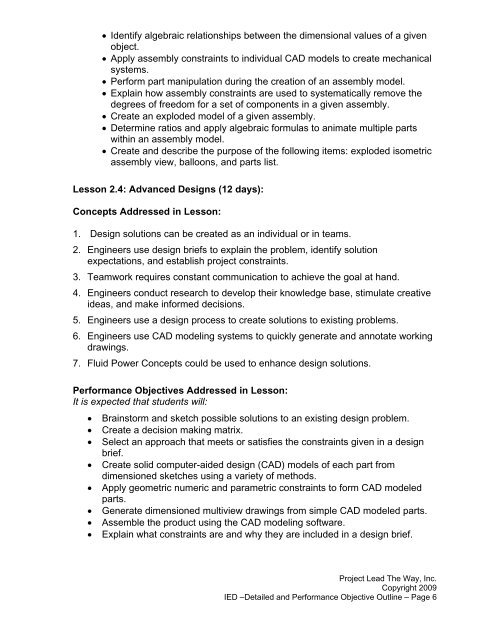
• Identify algebraic relationships between the dimensional values of a givenobject.• Apply assembly constraints <strong>to</strong> individual CAD models <strong>to</strong> create mechanicalsystems.• Perform part manipulation during the creation of an assembly model.• Explain how assembly constraints are used <strong>to</strong> systematically remove thedegrees of freedom for a set of components in a given assembly.• Create an exploded model of a given assembly.• Determine ratios and apply algebraic formulas <strong>to</strong> animate multiple partswithin an assembly model.• Create and describe the purpose of the following items: exploded isometricassembly view, balloons, and parts list.Lesson 2.4: Advanced <strong>Design</strong>s (12 days):Concepts Addressed in Lesson:1. <strong>Design</strong> solutions can be created as an individual or in teams.2. Engineers use design briefs <strong>to</strong> explain the problem, identify solutionexpectations, and establish project constraints.3. Teamwork requires constant communication <strong>to</strong> achieve the goal at hand.4. Engineers conduct research <strong>to</strong> develop their knowledge base, stimulate creativeideas, and make informed decisions.5. Engineers use a design process <strong>to</strong> create solutions <strong>to</strong> existing problems.6. Engineers use CAD modeling systems <strong>to</strong> quickly generate and annotate workingdrawings.7. Fluid Power Concepts could be used <strong>to</strong> enhance design solutions.Performance Objectives Addressed in Lesson:It is expected that students will:• Brains<strong>to</strong>rm and sketch possible solutions <strong>to</strong> an existing design problem.• Create a decision making matrix.• Select an approach that meets or satisfies the constraints given in a designbrief.• Create solid computer-aided design (CAD) models of each part fromdimensioned sketches using a variety of methods.• Apply geometric numeric and parametric constraints <strong>to</strong> form CAD modeledparts.• Generate dimensioned multiview drawings from simple CAD modeled parts.• Assemble the product using the CAD modeling software.• Explain what constraints are and why they are included in a design brief.Project Lead The Way, Inc.Copyright 2009IED –<strong>Detailed</strong> and Performance Objective <strong>Outline</strong> – Page 6


