Introduction to Engineering Design Detailed Outline
Introduction to Engineering Design Detailed Outline
Introduction to Engineering Design Detailed Outline

Create successful ePaper yourself
Turn your PDF publications into a flip-book with our unique Google optimized e-Paper software.
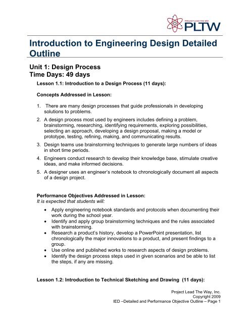
<strong>Introduction</strong> <strong>to</strong> <strong>Engineering</strong> <strong>Design</strong> <strong>Detailed</strong><strong>Outline</strong>Unit 1: <strong>Design</strong> ProcessTime Days: 49 daysLesson 1.1: <strong>Introduction</strong> <strong>to</strong> a <strong>Design</strong> Process (11 days):Concepts Addressed in Lesson:1. There are many design processes that guide professionals in developingsolutions <strong>to</strong> problems.2. A design process most used by engineers includes defining a problem,brains<strong>to</strong>rming, researching, identifying requirements, exploring possibilities,selecting an approach, developing a design proposal, making a model orpro<strong>to</strong>type, testing, refining, making, and communicating results.3. <strong>Design</strong> teams use brains<strong>to</strong>rming techniques <strong>to</strong> generate large numbers of ideasin short time periods.4. Engineers conduct research <strong>to</strong> develop their knowledge base, stimulate creativeideas, and make informed decisions.5. A designer uses an engineer’s notebook <strong>to</strong> chronologically document all aspectsof a design project.Performance Objectives Addressed in Lesson:It is expected that students will:• Apply engineering notebook standards and pro<strong>to</strong>cols when documenting theirwork during the school year.• Identify and apply group brains<strong>to</strong>rming techniques and the rules associatedwith brains<strong>to</strong>rming.• Research a product’s his<strong>to</strong>ry, develop a PowerPoint presentation, listchronologically the major innovations <strong>to</strong> a product, and present findings <strong>to</strong> agroup.• Use online and published works <strong>to</strong> research aspects of design problems.• Identify the design process steps used in given scenarios and be able <strong>to</strong> listthe steps, if any are missing.Lesson 1.2: <strong>Introduction</strong> <strong>to</strong> Technical Sketching and Drawing (11 days):Project Lead The Way, Inc.Copyright 2009IED –<strong>Detailed</strong> and Performance Objective <strong>Outline</strong> – Page 1
Concepts Addressed in Lesson:1. Engineers create sketches <strong>to</strong> quickly record, communicate, and investigateideas.2. Pic<strong>to</strong>rials and <strong>to</strong>nal shading techniques are used in combination <strong>to</strong> give sketchedobjects a realistic look.3. <strong>Design</strong>ers use isometric, oblique, perspective, and multiview sketching <strong>to</strong>maintain an object’s visual proportions.4. A multiview projection is the most common method of communicating the shapeand size of an object that is intended for manufacture.Performance Objectives Addressed in Lesson:It is expected that students will:• Identify, sketch, and explain the function of points, construction lines, objectlines, and hidden lines.• Plot points on grid paper <strong>to</strong> aid in the creation of sketches and drawings.• Explain the concepts of technical sketching and drawing.• Sketch an isometric view of simple geometric solids.• Explain how an oblique view of simple geometric solids differs from anisometric view.• Sketch one-point, two-point, and three-point perspectives of simple geometricsolids.• Describe the concept of proportion as it relates <strong>to</strong> freehand sketching.• Sketch multiview drawings of simple geometric solids.• Determine the front view for a given object.Lesson 1.3: Measurement and Statistics (10 days):Concepts Addressed in Lesson:1. Measurement systems were developed out of the need for standardization.2. Engineers apply dimensions <strong>to</strong> drawings <strong>to</strong> communicate size information.3. Manufactured parts are often created in different countries, where dimensionalvalues are often converted from one standard unit <strong>to</strong> another.4. The amount of variation that can be measured depends on the precision of themeasuring <strong>to</strong>ol.5. Statistical analysis of measurements can help <strong>to</strong> verify the quality of a design orprocess.6. Engineers use graphics <strong>to</strong> communicate patterns in recorded data.Performance Objectives Addressed in Lesson:It is expected that students will:Project Lead The Way, Inc.Copyright 2009IED –<strong>Detailed</strong> and Performance Objective <strong>Outline</strong> – Page 2
• Research and design a CD cover or book jacket on the origins of themeasurement systems.• Measure and record linear distances using a scale <strong>to</strong> a precision of 1/16inch and 1 mm.• Measure and record linear distances using a dial caliper <strong>to</strong> a precision of0.001 inch.• Add and subtract U.S. standard and metric linear measurements.• Convert linear distance measurements from inches <strong>to</strong> millimeters and viceversa.• Apply linear dimensions <strong>to</strong> a multiview drawing.• Calculate the mean, mode, median, and range of a data set.• Create a his<strong>to</strong>gram of recorded measurements showing data elements orclass intervals, and frequency.Lesson 1.4: Puzzle Cube (17 days):Concepts Addressed in Lesson:1. Three-dimensional forms are derived from two-dimensional shapes.2. The results of the design process are commonly displayed as a physical model.3. Engineers develop models <strong>to</strong> communicate and evaluate possible solutions.4. Geometric and numeric constraints are used <strong>to</strong> define the shape and size ofobjects in Computer Aided <strong>Design</strong> (CAD) modeling systems.5. Engineers use CAD modeling systems <strong>to</strong> quickly generate and annotate workingdrawings.6. Packaging not only protects a product, but contributes <strong>to</strong> that product’scommercial success.Performance Objectives Addressed in Lesson:It is expected that students will:• Brains<strong>to</strong>rm and sketch possible solutions <strong>to</strong> an existing design problem.• Select an approach that meets or satisfies the constraints given in a designbrief.• Create simple extruded solid Computer Aided <strong>Design</strong> (CAD) models fromdimensioned sketches.• Generate dimensioned multiview drawings from simple CAD models.• Measure and Fabricate parts for a functional pro<strong>to</strong>type from the CADmultiview drawings.• Assemble the product using the CAD modeling software.• Test and evaluate the pro<strong>to</strong>type and record results.• Apply geometric and numeric constraints <strong>to</strong> CAD sketches.• Identify the purpose of packaging in the design of consumer products.Project Lead The Way, Inc.Copyright 2009IED –<strong>Detailed</strong> and Performance Objective <strong>Outline</strong> – Page 3
Unit 2: <strong>Design</strong> ExercisesTime Days: 50 daysLesson 2.1: Geometric Shapes and Solids (10 days):Concepts Addressed in Lesson:1. Geometric shapes describe the two or three dimensional con<strong>to</strong>urs thatcharacterize an object.2. The properties of volume and surface area are common <strong>to</strong> all designed objectsand provide useful information <strong>to</strong> the engineer.3. CAD systems are used <strong>to</strong> increase productivity and reduce design costs.4. Solid CAD models are the result of both additive and subtractive processes.Performance Objectives Addressed in Lesson:It is expected that students will:• Identify common geometric shapes and forms by name.• Calculate the area of simple geometric shapes.• Calculate the surface area and volume of simple geometric forms.• Identify and explain the various geometric relationships that exist betweenthe elements of two-dimensional shapes and three-dimensional forms.• Identify and define the axes, planes, and sign conventions associated withthe Cartesian coordinate system.• Apply geometric and numeric constraints <strong>to</strong> CAD sketches.• Utilize sketch-based, work reference, and placed features <strong>to</strong> develop solidCAD models from dimensioned drawings.• Explain how a given object’s geometry is the result of sequential additiveand subtractive processes.Lesson 2.2: Dimensions and Tolerances (9 days):Concepts Addressed in Lesson:1. Working drawings should contain only the dimensions that are necessary <strong>to</strong> buildand inspect an object.2. Object features require specialized dimensions and symbols <strong>to</strong> communicatetechnical information, such as size.3. There is always a degree of variation between the actual manufactured objectand its dimensioned drawing.4. Engineers specify <strong>to</strong>lerances <strong>to</strong> indicate the amount of dimensional variation thatmay occur without adversely affecting an object’s function.5. Tolerances for mating part features are determined by the type of fit.Project Lead The Way, Inc.Copyright 2009IED –<strong>Detailed</strong> and Performance Objective <strong>Outline</strong> – Page 4
Performance Objectives Addressed in Lesson:It is expected that students will:• Explain the differences between size and location dimensions.• Differentiate between datum dimensioning and chain dimensioning.• Identify and dimension fillets, rounds, diameters, chamfers, holes, slots, andscrew threads in orthographic projection drawings.• Explain the rules that are associated with the application of dimensions <strong>to</strong>multiview drawings.• Identify, sketch, and explain the difference between general <strong>to</strong>lerances, limitdimensions, unilateral, and bilateral <strong>to</strong>lerances.• Differentiate between clearance and interference fits.Lesson 2.3: Advanced Modeling Skills (19 days):Concepts Addressed in Lesson:1. Solid modeling programs allow the designer <strong>to</strong> create quality designs forproduction in far less time than traditional design methods.2. Engineers use CAD models, assemblies, and animations <strong>to</strong> check for designproblems, verify the functional qualities of a design, and communicateinformation <strong>to</strong> other professionals and clients.3. Auxiliary views allow the engineer <strong>to</strong> communicate information about an object’sinclined surfaces that appear foreshortened in basic multiview drawings.4. <strong>Design</strong>ers use sectional views <strong>to</strong> communicate an object’s interior features thatmay be difficult <strong>to</strong> visualize from the outside.5. As individual objects are assembled <strong>to</strong>gether, their degrees of freedom aresystematically removed.6. Engineers create mathematical formulas <strong>to</strong> establish geometric and functionalrelationships within their designs.7. A title block provides the engineer and manufacturer with important informationabout an object and its crea<strong>to</strong>r.8. A parts list and balloons are used <strong>to</strong> identify individual components in anassembly drawing.Performance Objectives Addressed in Lesson:It is expected that students will:• Sketch and model an auxiliary view of a given object <strong>to</strong> communicate thetrue size and shape of its inclined surface.• Describe the purpose and demonstrate the application of section lines andcutting plane lines in a section view drawing.• Sketch a full and half section view of a given object <strong>to</strong> communicate itsinterior features.Project Lead The Way, Inc.Copyright 2009IED –<strong>Detailed</strong> and Performance Objective <strong>Outline</strong> – Page 5
• Identify algebraic relationships between the dimensional values of a givenobject.• Apply assembly constraints <strong>to</strong> individual CAD models <strong>to</strong> create mechanicalsystems.• Perform part manipulation during the creation of an assembly model.• Explain how assembly constraints are used <strong>to</strong> systematically remove thedegrees of freedom for a set of components in a given assembly.• Create an exploded model of a given assembly.• Determine ratios and apply algebraic formulas <strong>to</strong> animate multiple partswithin an assembly model.• Create and describe the purpose of the following items: exploded isometricassembly view, balloons, and parts list.Lesson 2.4: Advanced <strong>Design</strong>s (12 days):Concepts Addressed in Lesson:1. <strong>Design</strong> solutions can be created as an individual or in teams.2. Engineers use design briefs <strong>to</strong> explain the problem, identify solutionexpectations, and establish project constraints.3. Teamwork requires constant communication <strong>to</strong> achieve the goal at hand.4. Engineers conduct research <strong>to</strong> develop their knowledge base, stimulate creativeideas, and make informed decisions.5. Engineers use a design process <strong>to</strong> create solutions <strong>to</strong> existing problems.6. Engineers use CAD modeling systems <strong>to</strong> quickly generate and annotate workingdrawings.7. Fluid Power Concepts could be used <strong>to</strong> enhance design solutions.Performance Objectives Addressed in Lesson:It is expected that students will:• Brains<strong>to</strong>rm and sketch possible solutions <strong>to</strong> an existing design problem.• Create a decision making matrix.• Select an approach that meets or satisfies the constraints given in a designbrief.• Create solid computer-aided design (CAD) models of each part fromdimensioned sketches using a variety of methods.• Apply geometric numeric and parametric constraints <strong>to</strong> form CAD modeledparts.• Generate dimensioned multiview drawings from simple CAD modeled parts.• Assemble the product using the CAD modeling software.• Explain what constraints are and why they are included in a design brief.Project Lead The Way, Inc.Copyright 2009IED –<strong>Detailed</strong> and Performance Objective <strong>Outline</strong> – Page 6
• Create a three-fold brochure marketing the designed solution for the chosenproblem, such as a consumer product, a dispensing system, a new form ofcontrol system, or extend a product design <strong>to</strong> meet a new requirement.• Explain the concept of fluid power, and the difference between hydraulic andpneumatic power systems.Unit 3: Reverse <strong>Engineering</strong>Time Days: 43 daysLesson 3.1: Visual Analysis (8 Days):Concepts Addressed in Lesson:1. Visual design principles and elements constitute an aesthetic vocabulary that isused <strong>to</strong> describe any object independent of its formal title, structural, andfunctional qualities.2. Tangible design elements are manipulated according <strong>to</strong> conceptual designprinciples.3. Aesthetic appeal results from the interplay between design principles andelements.4. Though distinctly different, a design’s visual characteristics are influenced by itsstructural and functional requirements.5. Visual appeal influences a design’s commercial success.6. Graphic designers are concerned with developing visual messages that makepeople in a target audience respond in a predictable and favorable manner.Performance Objectives Addressed in Lesson:It is expected that students will:• Identify visual design elements within a given object.• Explain how visual design principles were used <strong>to</strong> manipulate designelements within a given object.• Explain what aesthetics is, and how it contributes <strong>to</strong> a design’s commercialsuccess.• Identify the purpose of packaging in the design of consumer products.• Identify visual design principles and elements that are present withinmarketing ads.• Identify the intent of a given marketing ad and demographics of the targetconsumer group for which it was intended.Lesson 3.2: Functional Analysis (4 Days):Concepts Addressed in Lesson:Project Lead The Way, Inc.Copyright 2009IED –<strong>Detailed</strong> and Performance Objective <strong>Outline</strong> – Page 7
1. Mechanisms use simple machines <strong>to</strong> move loads through the input of appliedeffort forces.2. Engineers perform reverse engineering on products <strong>to</strong> study their visual,functional, and structural qualities.3. Through observation and analysis, a product’s function can be divided in<strong>to</strong> asequence of operations.4. Products operate as systems, with identifiable inputs and outputs.Performance Objectives Addressed in Lesson:It is expected that students will:• Identify the reasons why engineers perform reverse engineering onproducts.• Describe the function of a given manufactured object as a sequence ofoperations through visual analysis and inspection (prior <strong>to</strong> dissection).Lesson 3.3: Structural Analysis (15 Days):Concepts Addressed in Lesson:1. Objects are held <strong>to</strong>gether by means of joinery, fasteners, or adhesives.2. Precision measurement <strong>to</strong>ols and techniques are used <strong>to</strong> accurately record anobject’s geometry.3. Operational conditions, material properties, and manufacturing methods helpengineers determine the material makeup of a design.4. Engineers use reference sources and computer-aided design (CAD) systems <strong>to</strong>calculate the mass properties of designed objects.Performance Objectives Addressed in Lesson:It is expected that students will:• Describe the differences between joinery, fasteners, and adhesives.• Identify the types of structural connections that exist in a given object.• Use dial calipers <strong>to</strong> precisely measure outside and inside diameter, holedepth, and object thickness.• Identify a given object’s material type.• Identify material processing methods that are used <strong>to</strong> manufacture thecomponents of a given commercial product.• Assign a density value <strong>to</strong> a material, and apply it <strong>to</strong> a given solid CADmodel.• Perform computer analysis <strong>to</strong> determine mass, volume, and surface area ofa given object.Project Lead The Way, Inc.Copyright 2009IED –<strong>Detailed</strong> and Performance Objective <strong>Outline</strong> – Page 8
Lesson 3.4: Product Improvement By <strong>Design</strong> (16 Days):Concepts Addressed in Lesson:1. Engineers analyze designs <strong>to</strong> identify shortcomings and opportunities forinnovation.2. <strong>Design</strong> teams use brains<strong>to</strong>rming techniques <strong>to</strong> generate large numbers of ideasin short time periods.3. Engineers use decision matrices <strong>to</strong> help make design decisions that are basedon analysis and logic.4. Engineers spend a great deal of time writing technical reports <strong>to</strong> explain projectinformation <strong>to</strong> various audiences.Performance Objectives Addressed in Lesson:It is expected that students will:• Write design briefs that focus on product innovation.• Identify group brains<strong>to</strong>rming techniques and the rules associated withbrains<strong>to</strong>rming.• Use decision matrices <strong>to</strong> make design decisions.• Explain the difference between invention and innovation.Unit 4: Open-Ended <strong>Design</strong> ProblemsTime: 33 DaysLesson 4.1: <strong>Engineering</strong> <strong>Design</strong> Ethics (8 Days):Concepts Addressed in Lesson:1. The material of a product, how the material is prepared for use, its durability, andease of recycling all impact a product’s design, marketability, and life expectancy.2. All products made, regardless of material type, may have both positive andnegative impacts.3. In addition <strong>to</strong> economics and resources, manufacturers must consider humanand global impacts of various manufacturing process options.4. Laws and guidelines have been established <strong>to</strong> protect humans and the globalenvironment.5. A conscious effort by product designers and engineers <strong>to</strong> investigate therecyclable uses of materials will play a vital role in the future of landfills and theenvironment.Project Lead The Way, Inc.Copyright 2009IED –<strong>Detailed</strong> and Performance Objective <strong>Outline</strong> – Page 9