Data and information technology - OBO Bettermann
Data and information technology - OBO Bettermann
Data and information technology - OBO Bettermann

Create successful ePaper yourself
Turn your PDF publications into a flip-book with our unique Google optimized e-Paper software.
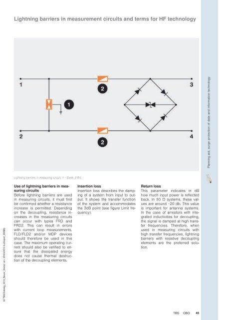
Lightning barriers in measurement circuits <strong>and</strong> terms for HF <strong>technology</strong>Planning aid, surge protection of data <strong>and</strong> <strong>information</strong> <strong>technology</strong>Lightning barriers in measuring circuit, 1 = Earth, 2 R/L02 TBS-Katalog_2010_Neuer_St<strong>and</strong> / en / 30/03/2010 (LLExport_00986)Use of lightning barriers in measuringcircuitsBefore lightning barriers are usedin measuring circuits, it must firstbe confirmed whether a resistanceincrease is permitted. Dependingon the decoupling, resistance increasesin the measuring circuitscan occur with types FRD <strong>and</strong>FRD2. This can result in errorswith current loop measurements.FLD/FLD2 <strong>and</strong>/or MDP devicesshould therefore be used in thiscase. The maximum operating currentshould also be verified to ensurethat the dissipated energydoes not cause thermal destructionof the decoupling elements.Insertion lossInsertion loss describes the dampingof a system from input to output.It shows the transfer functionof the system <strong>and</strong> accommodatesthe 3dB point (see figure Limit frequency).Return lossThis parameter indicates in dBhow much input power is reflectedback. In 50 Ω systems, these valuesare around −20 db. This valueis important for antenna systems.In the case of arrestors with integratedinductivities for decoupling,the signal is damped at high transferfrequencies. Therefore, whenused in measuring circuits withhigh transfer frequencies, lightningbarriers with resistive decouplingelements are the preferred solution.TBS<strong>OBO</strong>45