SIRENS AND CONTROLS - Code 3 Public Safety Equipment
SIRENS AND CONTROLS - Code 3 Public Safety Equipment
SIRENS AND CONTROLS - Code 3 Public Safety Equipment

You also want an ePaper? Increase the reach of your titles
YUMPU automatically turns print PDFs into web optimized ePapers that Google loves.
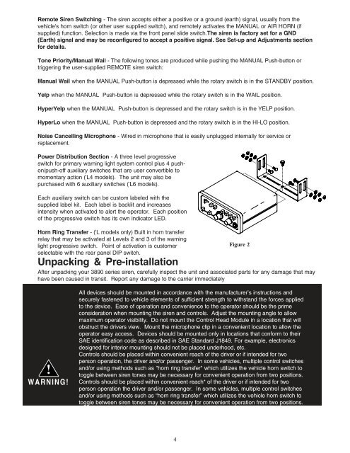
Remote Siren Switching - The siren accepts either a positive or a ground (earth) signal, usually from thevehicle's horn switch (or other user supplied switch), and remotely activates the MANUAL or AIR HORN (ifsupplied) function. Selection is made via the front panel slide switch.The siren is factory set for a GND(Earth) signal and may be reconfigured to accept a positive signal. See Set-up and Adjustments sectionfor details.Tone Priority/Manual Wail - The following tones are produced while pushing the MANUAL Push-button ortriggering the user-supplied REMOTE siren switch:Manual Wail when the MANUAL Push-button is depressed while the rotary switch is in the ST<strong>AND</strong>BY position.Yelp when the MANUAL Push-button is depressed while the rotary switch is in the WAIL position.HyperYelp when the MANUAL Push-button is depressed and the rotary switch is in the YELP position.HyperLo when the MANUAL Push-button is depressed and the rotary switch is in the HI-LO position.Noise Cancelling Microphone - Wired in microphone that is easily unplugged internally for service orreplacement.Power Distribution Section - A three level progressiveswitch for primary warning light system control plus 4 pushon/push-offauxiliary switches that are user convertible tomomentary action ('L4 models). The unit may also bepurchased with 6 auxiliary switches ('L6 models).Each auxiliary switch can be custom labeled with thesupplied label kit. Each label is backlit and increasesintensity when activated to alert the operator. Each positionof the progressive switch has its own indicator LED.Horn Ring Transfer - ('L models only) Built in horn transferrelay that may be activated at Levels 2 and 3 of the warninglight progressive switch. Point of activation is customerselectable with the rear panel DIP switch.Unpacking & Pre-installationFigure 2After unpacking your 3890 series siren, carefully inspect the unit and associated parts for any damage that mayhave been caused in transit. Report any damage to the carrier immediately!WARNING!All devices should be mounted in accordance with the manufacturer’s instructions andsecurely fastened to vehicle elements of sufficient strength to withstand the forces appliedto the device. Ease of operation and convenience to the operator should be the primeconsideration when mounting the siren and controls. Adjust the mounting angle to allowmaximum operator visibility. Do not mount the Control Head Module in a location that willobstruct the drivers view. Mount the microphone clip in a convenient location to allow theoperator easy access. Devices should be mounted only in locations that conform to theirSAE identification code as described in SAE Standard J1849. For example, electronicsdesigned for interior mounting should not be placed underhood, etc.Controls should be placed within convenient reach of the driver or if intended for twoperson operation, the driver and/or passenger. In some vehicles, multiple control switchesand/or using methods such as "horn ring transfer" which utilizes the vehicle horn switch totoggle between siren tones may be necessary for convenient operation from two positions.Controls should be placed within convenient reach* of the driver or if intended for twoperson operation the driver and/or passenger. In some vehicles, multiple control switchesand/or using methods such as “horn ring transfer” which utilizes the vehicle horn switch totoggle between siren tones may be necessary for convenient operation from two positions.4