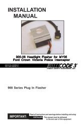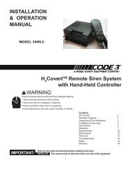
SIRENS AND CONTROLS - Code 3 Public Safety Equipment
SIRENS AND CONTROLS - Code 3 Public Safety Equipment
SIRENS AND CONTROLS - Code 3 Public Safety Equipment

Create successful ePaper yourself
Turn your PDF publications into a flip-book with our unique Google optimized e-Paper software.
REMOTE - Connect to the Remote terminal on the Siren Amplifier Connector.Lighting Models Only ( L versions )#8 GAUGE RED WIRE PIGTAIL - provides power to the 3 Level, progressive lighting outputs only.The wire can be ordered with an optional connector to allow for convenient removal. The connectorshould be soldered to each wire, NOT crimped. This connection is designed to provide 50 ampservice and therefore nothing smaller than #8 guage wire should be connected to it.The circuit breakerused should be sized for the actual load of the lighting used and located as close to the batterypositive as possible. For quick disconnection option on 8 AWG wire see "lighting switch connector"on page 23.4 Position Screw-type Terminal Block ConnectorImportant!The total combined current for the auxillary outputs A,B,D on L4 models and A,B,D,E,F on L6models must not exceed 30 Amps total.+12VAUX - Connect to the positive terminal of the battery with 30 Amp circuit protection. Locate thefuse or circuit breaker at the battery and use #10 gauge wire minimum. This terminal powersswitches A,B and D on L4 models and A,B,D,E and F on L6 models, and also supplied power to thesiren lock & light alert circuits on both models.LEVEL 1 - Connect to the first level of warning lights (Green LED) position "1" on level switch.LEVEL 2 - Connect to the second level of warning lights (Yellow LED) position "2" on level switch.LEVEL 3 - Connect to the third level of warning lights (Red LED) position "3" on level switch.NOTE: LEVEL 1, LEVEL 2, LEVEL 3, switch progressively. Switch position 1 provides +12 volts atLevel 1 terminal. Switch position 2 provides +12 volts at terminals 1 and 2. Switch position 3provides +12 volts at terminals 1, 2, and 3.SET-UP <strong>AND</strong> ADJUSTMENTAll of the adjustments, except MAXIMUM P.A. ADJUSTMENT, and set-up switches areaccessible from the rear of the unit. Make these adjustments and position the set-up switches priorto placing the unit inside their bail bracket (see wiring diagram, page 20).Audio AdjustmentsRadio Rebroadcast Adjustment - Place the selector switch in the RADIO position. The trimmerlocated on the rear panel of the siren sets the maximum level RRB will reach with the knob fullyclockwise. To adjust properly, set the volume knob fully clockwise and adjust the trimmer such thatnormal two-way radio volume inside the vehicle produces the desired volume outside the vehicle.Maximum P.A. Volume Adjustment - This trimmer ( located on the front panel next to the volumecontrol knob ) sets the maximum level that the P.A. volume will reach with the front panel VOLUMEcontrol in the fully clockwise position.To adjust properly, set the front panel volume control fullyclockwise and adjust the trimmer while keying the microphone until the maximum volume out of thespeaker is such that there is no feedback and is intelligible. (See Figure 1)8