7.0 Geology and Geomorphology - Origin Energy
7.0 Geology and Geomorphology - Origin Energy
7.0 Geology and Geomorphology - Origin Energy

You also want an ePaper? Increase the reach of your titles
YUMPU automatically turns print PDFs into web optimized ePapers that Google loves.
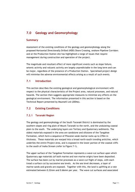
<strong>7.0</strong> <strong>Geology</strong> <strong>and</strong> <strong>Geomorphology</strong>SummaryAssessment of the existing conditions of the geology <strong>and</strong> geomorphology along theproposed Horizontal Directionally Drilled (HDD) Shore Crossing, onshore Pipeline Corridors<strong>and</strong> at the Production Station site has highlighted a range of issues that requiremanagement during construction <strong>and</strong> operation of the project.The magnitude <strong>and</strong> resultant effect of more significant events such as slope failure,seismic activity <strong>and</strong> volcanic activity are largely unpredictable in the long term <strong>and</strong> canbe major, regardless of the presence of a Production Station. Specialised project designwill minimise the adverse environmental effects arising as a result of such events.7.1 IntroductionThis section describes the existing geological <strong>and</strong> geomorphological environment withrespect to the physical characteristics of the Project area, natural processes, <strong>and</strong> naturalhazards. The section then suggests appropriate measures to minimise any effects on thegeological environment. The information presented in this section is based on theTechnical Report presented by Maunsell Ltd (2004a).7.2 Existing Conditions7.2.1 Taranaki RegionThe geology <strong>and</strong> geomorphology of the South Taranaki District is dominated by thesouthern slopes <strong>and</strong> ring plain of Mount Taranaki to the north, <strong>and</strong> the undulating coastalplain to the south. The underlying layers are Tertiary <strong>and</strong> Quaternary sediments. Theoldest materials exposed in the area are s<strong>and</strong>stone <strong>and</strong> siltstone of the TangahoeFormation, which form a sequence of Pliocene weak marine rocks up to 270m inthickness. These materials are warped into a broad north-south trending anticline, whichunderlies the entire Project Area, <strong>and</strong> is exposed in the lower portion of the coastal cliffsto the south of Inaha Stream (refer to Figure 7-1).The upper surface of the Tangahoe Formation represents a wave-cut surface upon whichQuaternary age materials (of both marine <strong>and</strong> non-marine origin) have been deposited.The surface has been cut by marine processes as a wave-cut flight of steps, with eachtread a surface cut by successive sea levels. As the sea level decreases, a layer ofmarine s<strong>and</strong>s <strong>and</strong> gravels are exposed. Together with this, the l<strong>and</strong> is uplifting at a rateestimated between 0.22mm <strong>and</strong> 0.66mm per year. The wave cut surfaces <strong>and</strong> associatedSection 7 – <strong>Geology</strong> Page 7-1
deposits are between 60,000 <strong>and</strong> 680,000 years old, <strong>and</strong> have subsequently been buriedby terrestrial sediments, particularly alluvium <strong>and</strong> volcanic materials.The southern reaches of Mount Taranaki extend to the coast where the volcanic ring plainmaterials are exposed. The ring plain is approximately 30m thick adjacent to the InahaStream.Deeply incised streams <strong>and</strong> rivers originate high on the mountain flanks <strong>and</strong> flow towardthe coast. Kapuni Stream, the most significant stream to flow through the Project Area,is located to the west of the proposed Production Station location. The ground surfacebetween the streams is flat <strong>and</strong> underlain predominately by volcanic air-fall ash <strong>and</strong>lahar deposits of which are 1m to 5m thick. Slope instability is a potential issue in thesteep slopes adjacent to the watercourses, which are typically greater than 20 o .Principal areas where slope instability could have an effect on the Project include thecliff section at the Shore Crossing <strong>and</strong> the slopes bounding the Inaha <strong>and</strong> Kapuni Streams.Cliff regression in the Taranaki region is significant due to the high energy nature of themarine processes. Studies undertaken to assess the rate of regression indicate a ratebetween 0.05m/year to 1.11m/year. Figure 7-2 shows cliff regression in the SouthTaranaki region.7.2.2 General Project AreaThe onshore component of the Project Area includes high coastal cliffs backed by flattopography, incised with occasional steep river valleys. The underlying geology of theProject Area is comprised of Quaternary deposits with weak Pliocene rock, which isexposed in the river valleys <strong>and</strong> along the cliffs. Near surface deposition includesvolcanic ash dune s<strong>and</strong>, alluvium <strong>and</strong> colluvium.Page 7-2Section 7 – <strong>Geology</strong>
ACKapuniStreamInaha Road40mDProductionStation SiteLEGENDAndesitic Ash Covers Quaternary materials to a depth of 3mto 5m. Shown on section only.Alluvium – silt, s<strong>and</strong> gravel <strong>and</strong> boulders derived from laharHDD SitemN6180000Lahar – layered dense s<strong>and</strong> <strong>and</strong> silt with gravel <strong>and</strong> <strong>and</strong>esiticboulders up to 3m in diameter. Covered by 3m to5m of <strong>and</strong>esitic ashQuaternary Deposits – layered dense s<strong>and</strong> with minor gravel<strong>and</strong> carbonaceous bedsInaha StreamTangahoe Formation – Weak muddy s<strong>and</strong>stone <strong>and</strong> siltstone.Likely profile 2054 if regressioncontinues at measured rates0.1 metre/year0.2metre/year40m20mConvex Slope BreakConcave Slope BreakHeight ContourArea susceptible toslope instabilityCliff 35m to 40m0m 200m 400m 600m 800m 1000mShore CrossingBSouth TaranakiBightA B40m0mC D40m0m0m 100m 200m 300m 400m 500mFigure 7-1 : Production Station Site <strong>and</strong> Shore Crossing - Geological Plan <strong>and</strong> Section103683720 JPU July 04Section Scale 1:5,000
OnshorePipeline RouteProductionStationSiteG1350.16m/yrG1340.34m/yrShore CrossingAverage 0.1m/yrMin 0m/yrMax 0.2m/yrG1331.11m/yrG131,132G1300.32m/yrG1290.6m/yr<strong>Geology</strong>LEGENDDune S<strong>and</strong>Alluvium – silt, s<strong>and</strong> <strong>and</strong> gravel.Ring Plain Deposits - Lahar <strong>and</strong> debris flow materials. Covered in part by 1m to 5mof <strong>and</strong>esitic ash. Underlain at depth by Tangahoe Formationweak rockQuaternary Deposits – Dense s<strong>and</strong> <strong>and</strong> gravel, thin Lignite beds. Covered in part by 1mto 5m of <strong>and</strong>esitic ash or dunes. Underlain at depth byTangahoe Formation weak rockExtent ofringplainunclearArarata FaultG1280.54m/yrG1270.67m/yrRimuProductionStationG1260.42m/yrG1250.05m/yrTaranaki Regional CouncilL<strong>and</strong>form DescriptionCoastal TerracesCoastal S<strong>and</strong> Country Active FaultSiteInterval CliffRegressionFrom ToRate125 Power House Road 1901 1976 75yrs 0.05m/yr126 Manutahi Road 1874 1927 53yrs 0.42m/yr127 Manawapou 1874 1976 102yrs 0.67m/yr128 Manawapou 1874 1976 102yrs 0.54m/yr129 Siggs Trig 1908 1958 50yrs 0.60m/yr130 Hauroto Road 1902 1930 28yrs 0.32m/yr131 Ohawe Beach 1871 1966 95yrs 0.63m/yr132 Ohawe Beach 1871 1966 95yrs 0.63m/yr133 Raine Road 1940 1976 36yrs 1.11m/yr134 Winks trig 1872 1976 104yrs 0.34m/yr135 Normanby Road 1879 1930 51yrs 0.16m/yrCliff Regression Rates from Gibb (1979)0km 6km 8km 10km2km 4kmAs ShownFigure 7-2 : Cliff Regression
7.2.3 HDD Shore CrossingThe coastal cliffs are approximately 40m high, as shown in Figure 7-3. Also significant is thatthey are actively regressing at a rate assessed at up to 0.2m a year. Other sections of thecoast in the South Taranaki region are regressing up to 1m per year. The farml<strong>and</strong>topography continues to the cliff-edge, with no s<strong>and</strong> dunes to provide any form ofprotection.Figure 7-3: Coastal Cliffs Adjacent to Project AreaFigure 7-4 shows a cross section of the geology underlying the coastal area at the HDD ShoreCrossing location. The cliff is underlain by a sequence of Pliocene weak rock to an elevationof 0m to 9m. This material extends to at least 100m below sea level. The Pliocene rock isoverlain by Quaternary deposits comprising a thin marine sequence of s<strong>and</strong>, gravel <strong>and</strong>boulders, as well as a thicker, non-marine sequence of dense s<strong>and</strong> <strong>and</strong> thin coal seams. TheQuaternary layer is approximately 10m thick, <strong>and</strong> lies under lahar <strong>and</strong> debris flow materials(silt, s<strong>and</strong> <strong>and</strong> boulders up to 3m diameter). The upper layer is a mantle of <strong>and</strong>esitic ash 2mto 3m thick. Figure 7-4 also presents two cliff regression scenarios showing the position ofthe cliffs in 2054 under two different regression rates of 0.1m/year, <strong>and</strong> 0.2m/year.Section 7 – <strong>Geology</strong> Page 7-5
Figure 7-4: Cross Section of Cliff <strong>Geology</strong>Page 7-6 Section 7 – <strong>Geology</strong>
7.2.4 Production Station SiteThe proposed Production Station site will be located on l<strong>and</strong> at an elevation ofapproximately 45m above sea level. The topography of the site is characterised byfeatures consistent with the broader area – typically flat with gentle undulations havingslopes generally less than 10 o . Near the western edge of the site, a steep 8m slopedescends to a lower flat terrace level. Figure 7-5 shows a photo of the local ProductionStation area.Figure 7-5: Overlooking the Production Station site towards the West7.2.5 Onshore Pipeline CorridorThe onshore Pipeline Corridor between the Production Station site <strong>and</strong> the Kapuni GasTreatment Plant crosses one major watercourse (Kapuni Stream), <strong>and</strong> a tributary of InahaStream. Typically, steep banks in excess of 20 o are associated with major streams, whilesmall streams generally have moderate slopes of between 10 o to 20 o . The ground surfacebetween the watercourses along the pipeline route is gently undulating with slopes up toSection 7 – <strong>Geology</strong> Page 7-7
10 o . Between watercourses the excavation will be in volcanic ash. The stream crossingswill require excavation of material such as alluvium, weak rock, dense s<strong>and</strong> <strong>and</strong>colluvium. Boulders up to 3m in diameter may be encountered within the stream banks<strong>and</strong> bed.7.2.6 Other FeaturesSlope StabilitySlope instability is a potential issue in the steep slopes adjacent to the watercourses,which are typically greater than 20 o . Principal areas where slope instability could havean effect on the Project include the cliff section at the Shore Crossing <strong>and</strong> the slopesbounding the Inaha <strong>and</strong> Kapuni Streams.SoilsInl<strong>and</strong> areas are predominately brown loams with river <strong>and</strong> stream valley floors <strong>and</strong> floodplains underlain by s<strong>and</strong>y loams <strong>and</strong> s<strong>and</strong>. Within 2km to 3km of the coast black loamsoils predominate with s<strong>and</strong> at some locations near the coast.Seismicity <strong>and</strong> FaultingThe nearest recorded active fault is the Ararata Fault (Stirling et. al. 2000)approximately 17km to the east (refer to Figure 7-2). The Ararata fault has a recurrenceinterval of approximately 17,000 years. The Cape Egmont Fault is offshore approximately35km to the east with a recurrence interval of approximately 3,000 years, <strong>and</strong> the OaonuiFault is approximately 35km to the north-west with a recurrence interval of 2,200 years(Stirling et. al. 2000). No active faulting is recorded as intersecting the proposeddevelopment area. In terms of the AS/NZS1170.4 (St<strong>and</strong>ards New Zeal<strong>and</strong> 2003) most ofthe site is underlain by subsoil class C, <strong>and</strong> has a hazard factor (z) of 0.19 for the 1/500year earthquake with the nearest major fault being the Wellington Fault approximately150 km to the south east (St<strong>and</strong>ards New Zeal<strong>and</strong> 2003). To put this in a larger contextAuckl<strong>and</strong> has a hazard factor (z) of 0.13 <strong>and</strong> Wellington Central Business District 0.44.The Kupe Gas Project undertook a site-specific seismic assessment for design for themajor infrastructure components.VolcanismThe area can potentially be affected by volcanism originating in the mid North Isl<strong>and</strong>(Taupo Volcanic Zone) <strong>and</strong> from nearby Mt Taranaki. Mt Taranaki is the more threatening<strong>and</strong> it last erupted in 1755 (Neall et. al. 1986). Volcanic hazards are lahar <strong>and</strong> debrisflows down existing stream <strong>and</strong> river channels <strong>and</strong> ash fall (Figure 7-5), these hazards aremore acute in the East due to prevailing westerly winds.The Taranaki Regional Volcanic Strategy (TRC 1998) presents six categories of laharhazard, of which the following encompass the Project Area:Page 7-8Section 7 – <strong>Geology</strong>
• level 3: Likely to be affected most severely <strong>and</strong> most frequently by debrisavalanches, lahars <strong>and</strong> floods• level 4: Could be affected by debris avalanches, lahars <strong>and</strong> floods (unusuallylarge but infrequent lahars <strong>and</strong> floods)• level 5: Could be affected by rare, volcanic debris flows, lahars <strong>and</strong> floods.The Production Station is located within an area with a level 4 lahar hazard. The pipelineroute traverses areas with 3, 4 <strong>and</strong> 5 lahar hazard.The TRC (1998) outlines four categories of ash fall thickness, <strong>and</strong> the Project Area lieswithin:• zone B: Possible depth of ash deposit from eruption, 0.1m to 0.25m• zone C: Possible depth of ash deposit from eruption 0.01m to 0.1m.The Production Station is located within zone C ashfall thickness <strong>and</strong> the pipeline routetraverses zones C <strong>and</strong> B.MiningWithin the Project Area, there are four identified Crown Mineral Permits relating topetroleum, two onshore <strong>and</strong> two offshore. There are no current mines in the area,however a small quarry operates near the Kapuni Stream bank west of the ProductionStation Site. It not known whether any historical mineral extraction has occurred.Section 7 – <strong>Geology</strong> Page 7-9
Figure 7-5: VolcanismKapuniProductionStationAsh FallZone BAsh FallZone CKapuniStreamProductionStationSiteLEGEND345Likely to be affected most severely <strong>and</strong> most frequently bydebris avalanches, lahars <strong>and</strong> floodsCould be affected (unusually large but infrequent lahars<strong>and</strong> floods)Could be affected by rare, volcanic debris, lahars <strong>and</strong> floodsAsh Fall Zone BAsh Fall Zone CPossible depth of ash deposit from eruption0.1m to 0.25mPossible depth of ash deposit from eruption0.01m to 0.1mPage 7-10Section 7 – <strong>Geology</strong>
7.3 Environmental Effects Assessment7.3.1 Shore CrossingConstructionThe geological <strong>and</strong> geomorphological effects which could potentially be encounteredduring construction of the shore crossing are:• possible instability in the coastal cliff zone caused by drilling disturbance <strong>and</strong>vibration• soil contamination by drilling fluid leakage during the pipe drilling operation• cliff slope instability caused by rupture <strong>and</strong>/or leakage from the pipeline duringtesting or installation• soil contamination by accidental spillage of fuels or lubricants stored on site forthe drilling rig• soil erosion from cliff instability due to HDD.OperationAs the pipeline will be buried during operation, only activity from natural hazards, maycreate geological <strong>and</strong> geomorphological effects. These are:• regression of the cliff by erosion, potentially exposing the pipe <strong>and</strong> possiblycausing a breach which may leak• seismic shaking of the pipe causing ground contamination from possible rupture<strong>and</strong> leakageDecommissioningIt is proposed to leave the pipe in place after operation has ceased <strong>and</strong> as such noenvironmental effect has been identified.7.3.2 Production StationThe Production Station will cover an area of approximately 350m by 500m, on flat groundbetween the Inaha <strong>and</strong> Kapuni Streams.ConstructionThe construction of the Production Station will involve some minor earthworks across thesite to level it out <strong>and</strong> prepare foundations <strong>and</strong> paved areas. The western edge of thesite is the closest point to Kapuni Stream. The potential geological <strong>and</strong> geomorphologicaleffects are:• slope instability at the stream banks <strong>and</strong> on the 8m high slope at the western endof the site caused by construction activities, particularly on steeper slopesSection 7 – <strong>Geology</strong> Page 7-11
• soil contamination by accidental spillage of fuels or lubricants by constructionequipment.OperationPotential issues that may be encountered during operation of the Production Stationinclude:• compromised stability of steep ground near the Kapuni Stream from earthquakeshaking• shaking of the plant by earthquakes, potentially leading to soil contamination byaccidental spillage of site chemicals or rupture of pipes• volcanic hazard which may compromise the integrity of plant structures to such adegree as to cause spillages <strong>and</strong> accidental discharge of petrochemicals <strong>and</strong> otherchemicals.DecommissioningThe plant will be dismantled <strong>and</strong> the site reinstated to its existing condition. Potentialissues that may be encountered during decommissioning works <strong>and</strong> after decommissioninginclude:• soil erosion from earthworks• contamination of the soil from leaks of fuels <strong>and</strong> lubricants.7.3.3 Onshore PipelinesThe combined length of the onshore pipeline corridors is approximately 11km, crossingflat <strong>and</strong> gently undulating ground. The effects potentially arising as a result of theconstruction, operation <strong>and</strong> decommissioning of the onshore pipelines are describedbelow.ConstructionThe construction corridor will be 15-20m wide over the required length of the pipelines,<strong>and</strong> all works will be temporary. The potential geological <strong>and</strong> geomorphological effectsassociated with construction of the onshore pipelines are:• general construction:− The inappropriate h<strong>and</strong>ling <strong>and</strong> storage of fuels <strong>and</strong> lubricants leading tocontamination of soil at the site• while trenching flat to undulating ground:− Soil degradation <strong>and</strong> water course sedimentation by soil erosion− Support in trenching works, or additional support to embankments may berequired− Collapse of temporary works (trench walls, cuts)− Instability of steep slopes near the Kapuni <strong>and</strong> Inaha Streams, especiallyduring trenching work associated with pipeline layingPage 7-12Section 7 – <strong>Geology</strong>
OperationPotential effects during operation include:• slope instability adjacent to streams with associated soil erosion, resulting insedimentation to water courses• seismic shaking of the pipe may cause pipeline rupture, potentially leading to soilcontamination <strong>and</strong>/or erosion• lahar <strong>and</strong> debris flows at stream crossings may move the pipelines enough torupture them, once again creating potential for pipeline rupture <strong>and</strong> discharge ofcontaminants.DecommissioningThe pipe is to be degassed <strong>and</strong> pigged to render it safe <strong>and</strong> will remain in place afteroperation has ceased. No geological or geomorphological effects will result.7.4 Mitigation7.4.1 Shore CrossingAt the Shore Crossing, any constraints posed by the topography will be overcome byconducting directional drilling beneath the coastal cliff zone for placement of thepipeline shore crossing.During the operational phase of the HDD Shore Crossing component of the pipeline, asignificant seismic event presents the most significant risk. The risk is that a seismicevent may induce pipeline rupture with the associated threat of escaping fluids inducinginstability of the cliff slopes <strong>and</strong> polluting the marine environment. On the availablegeological <strong>and</strong> seismological evidence, the potential for such a seismic event is low.Operational effects can be mitigated or avoided through suitable upfront design of theShore Crossing to allow for severe cliff regression, <strong>and</strong> site-specific seismic assessment,as well as reinstatement of appropriate vegetation at the HDD entry site.7.4.2 Production StationMitigation measures for potential effects resulting from the construction of theProduction Station include implementing a sediment control plan for the site, <strong>and</strong>appropriate detailed geotechnical investigation <strong>and</strong> design for any works on potentiallyunstable ground.Mitigation measures for operational effects include slope stabilisation plans, site-specificseismic assessment <strong>and</strong> design, plant design to account for volcanic ash, as well asSection 7 – <strong>Geology</strong> Page 7-13
l<strong>and</strong>scaping to prevent soil erosion. Operational processes to minimise issues related tothese effects will be described in environmental management plans for the facility.These management measures include ensuring areas of potentially erosive soils <strong>and</strong>unstable slopes are stabilised <strong>and</strong> that monitoring <strong>and</strong> maintenance of revegetated areas.To avoid or mitigate effects as a result of decommissioning a suitable sediment controlplan will be developed <strong>and</strong> implemented to reduce sediment runoff from the site.7.4.3 Onshore PipelineConstruction effects will be mitigated through the development <strong>and</strong> implementation ofsoil erosion <strong>and</strong> waste disposal plans, minimising the works areas, <strong>and</strong> utilisingappropriate design for steep areas. Mitigation of potential operational effects involves athorough seismic assessment of the project area, appropriate design for steep ground,avoiding bridge crossings, <strong>and</strong> reinstatement of vegetation to prevent erosion.The soils in the Project area will be managed using appropriate erosion control measuresas detailed in the TRC’s Guidelines for Earthworks in Taranaki. Appropriate techniqueswill need to be employed during pipe laying works to avoid disruption to natural watercourses. Some softer soils may be prone to gully erosion where exposed by vegetationremoval <strong>and</strong> trenching activity. Soils exposed in the pipeline construction process will beproperly stabilised for soil erosion to be managed during the operational phase. In theevent that it is not possible to avoid potentially unstable slopes, the risk of damage tothe pipeline will be reduced by site specific engineering design. Where the pipelinecrosses a natural waterway, the design will ensure effective scour protection.It is important to note that the pipelines will be designed for the moderate seismic <strong>and</strong>volcanic hazards in the region by avoiding steep slopes that may be unstable <strong>and</strong> byconstructing stream crossings using boring or HDD techniques where possible.7.5 Conclusion <strong>and</strong> RecommendationsAssessment of the existing conditions of the geology <strong>and</strong> geomorphology along theproposed HDD Shore Crossing, Pipeline Corridors <strong>and</strong> at the Production Station site hashighlighted a range of issues that require management during construction <strong>and</strong> operationof the Project.The potential for adverse geological <strong>and</strong> geomorphological effects are considered torange between “moderate” <strong>and</strong> “very low”, many of which could arise throughinadequate management of the construction sites. Appropriate management plans willbe prepared to mitigate these potential adverse effects.Page 7-14Section 7 – <strong>Geology</strong>
The magnitude <strong>and</strong> resultant effect of more significant events such as slope failure,seismic activity <strong>and</strong> volcanic activity are largely unpredictable in the long term <strong>and</strong> canbe major, regardless of the presence of a Production Station. Specialised project designwill minimise the adverse environmental effects arising as a result of such events.Section 7 – <strong>Geology</strong> Page 7-15
Table 7-1 : Environmental Hazards, Risks <strong>and</strong> MitigationPhase Activities Potential Effect Mitigation Mitigated EffectShore CrossingConstructionDrill cuttings, drilling mud, pipe thrustlubricant (bentonite)Construction EarthworksOperation Seismic ground shakingSpillage on disposal of drilling cuttings <strong>and</strong> mud Containment, recirculation <strong>and</strong> disposal by appropriate methods MinorRupture <strong>and</strong>/or leakage of pipeline Automated shutdown of pipeline loss of pressure. MinorContamination of soil Management <strong>and</strong> reinstatement of HDD site, Disposal by appropriate MinormethodsSoil erosion Appropriate erosion <strong>and</strong> sediment control measures <strong>and</strong> l<strong>and</strong>scape design MinorContamination of soil Treatment <strong>and</strong> disposal by appropriate methods MinorGround contamination from rupture <strong>and</strong>/or leakage of Seismic design of pipeline MinorpipelineRegression of cliff by erosion Appropriate set back of HDD from edge of cliff MinorDecommissioning Erosion from site platform Soil degradation <strong>and</strong> sedimentation of surface water Implement sediment control plan MinorFuel or lubricant leakage from equipment Contamination of soil Treatment <strong>and</strong> disposal by appropriate methods MinorProduction StationConstruction Earthworks sediment runoff Soil degradation <strong>and</strong> sedimentation of surface water Implement sediment control plan MinorFuel or lubricant leakage from equipment Contamination of soil Treatment <strong>and</strong> disposal by appropriate methods MinorSlope instability along Kapuni Stream bank Failure into stream with sedimentation Appropriate geotechnical assessment <strong>and</strong> designs. Avoid affected areas if MinorpossibleOperation Slope instability along Kapuni Stream Failure into stream with sedimentation Appropriate geotechnical assessment <strong>and</strong> designs. Avoid affected areas if Minorpossible.Seismic ground shaking Plant failure, spill, fire, explosion Site specific seismic design of Production Station Moderate/Minor *1Lahar inundation Plant failure, spill, fire, explosion Site specific plant design on high ground Moderate/Minor *1Volcanic ash fall Plant failure, spill, fire, explosion Allow for in design of control mechanisms Moderate/Minor *1Decommissioning Erosion from site platform Soil degradation <strong>and</strong> sedimentation of surface water Appropriate l<strong>and</strong>scape design with soil conservation measures. MinorFuel or lubricant leakage from equipment Contamination of soil Treatment <strong>and</strong> disposal by appropriate methods MinorSales Gas PipelineConstructionEarthworks sediment runoff/soil erosion Disruption to natural water courses Appropriate erosion <strong>and</strong> sediment control measures <strong>and</strong> rehabilitation MinorSedimentation of surface water Implement sediment control plan MinorSlope instability Failure into stream Route alignment to avoid unstable areas <strong>and</strong> appropriate geotechnical MinordesignFuel or lubricant leakage from equipment Contamination of soil Treatment <strong>and</strong> disposal by appropriate methods MinorOperation Slope instability Rupture <strong>and</strong>/or leakage of pipeline Seismic design of pipeline <strong>and</strong> assessment of each cut <strong>and</strong> fill MinorLahar inundation at stream crossing Rupture <strong>and</strong>/or leakage of pipeline Bury stream crossing in preference to pipe bridges where feasible. MinorSeismic ground shaking Rupture <strong>and</strong>/or leakage of pipeline Seismic design of Pipeline MinorStream bed erosion Pipe exposed in stream bed Bury at appropriate depth below stream bed MinorDecommissioning Fuel, lubricant or flushing fluid leakage from Contamination of soil/ surface water Treatment <strong>and</strong> disposal by appropriate methods MinorequipmentNote :*1It is anticipated that with appropriate design it will be possible to mitigate these risks to minor.Page 7-16 Section 7 – <strong>Geology</strong>