Pig Trap Design And Assessment Considerations - T.D. Williamson ...
Pig Trap Design And Assessment Considerations - T.D. Williamson ...
Pig Trap Design And Assessment Considerations - T.D. Williamson ...

You also want an ePaper? Increase the reach of your titles
YUMPU automatically turns print PDFs into web optimized ePapers that Google loves.
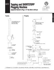
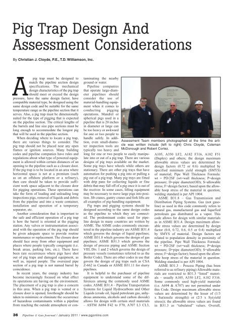
<strong>Pig</strong> <strong>Trap</strong> <strong>Design</strong> <strong>And</strong><strong>Assessment</strong> <strong>Considerations</strong>By Christian J. Cloyde, P.E., T.D. <strong>Williamson</strong>, Inc.Apig trap must be designed tomatch the pipeline section designspecifications. The mechanicaldesign characteristics of the pig trapshould meet or exceed the designpressure, have the same design factor, havecompatible material type, be designed using thesame design code and be suitable for the sametemperature range as the pipeline section that itserves. Also, a pig trap must be dimensionallysuited for the type of pigging that is expectedon the pipeline section. The critical lengths ofthe barrels and line size pipe sections must belong enough to accommodate the longest pigthat will be used in the pipeline section.When deciding where to locate a pig trap,there are various things to consider. Thepig trap should not be placed near any openflames or ignition sources. Many buildingcodes and pipeline companies have rules andregulations about what type of powered equipmentis allowed within certain distances of anopening to the pipeline such as a closure door.If the pig trap is to be located in an area wherehorizontal space is not at a premium (suchas on an offshore platform or a refinery),then care should be taken to provide sufficientwork space adjacent to the closure doorfor pigging operations. These operations cantake the form of loading and unloading longinspections pigs, removal of liquids and debrisfrom the pipeline and into a waste container,installation and operation of a temporaryseparator, etc.Another consideration that is important tothe safe and efficient operation of a pig trapis how the barrel is oriented at the piggingstation. Any valves or instrumentation associatedwith the operation of the pig trap shouldbe given adequate space to provide routinemaintenance or replacement. The closure doorshould face away from other equipment andplaces where people typically congregate (i.e.break areas, parking lots, etc.). There havebeen rare occurrences where pigs have shotout of pig traps and damaged equipment, aswell as, injured people. The oversized pipesection of a pig trap is not named barrel bycoincidence.In recent years, the energy industry hasbecome increasingly focused on what effectits operations are having on the environment.The placement of a pig trap is also a concernin this area. When a pig trap is vented or aclosure door is opened, forethought should betaken to minimize or eliminate the occurrenceof hazardous contaminants within a pipelinefrom reaching the outside atmosphere or con-taminating the nearbyground or water.Pipeline companiesthat operate large-diameterpipelines shouldconsider the use ofmaterial-handling equipmentwhen it comes toconducting piggingoperations. Mandrel orspherical pigs used in apipeline that is 20 inchesin diameter or large canbe too heavy or awkwardfor one or two people tohandle safely. In addition,even small-diameterinspection tools aretypically too heavy andlong for one or two people to easily manipulateinto or out of a pig trap. There are variousdesigns of pig trays available on the market.Some pig trays have wheels while others arestationary. There are other pig trays that haveautomation for pushing a pig into or pulling apig out of a pig trap. Many pig trays are fittedwith drip pans for collecting liquids or finedebris that may fall off of a pig once it is out ofthe receiver. In some cases, lifting equipmentmay be necessary to move large pigs into position.Jib cranes, gantry cranes and fork lifts areall examples of pig-handling equipment.<strong>Pig</strong> traps and pigging systems should bedesigned according to the same design codesas the pipeline to which they are connected.The predominant codes used for pipelinedesign in many countries are written byASME. The ASME codes commonly encounteredin the pipeline industry are ASME B31.4which governs the design of liquid pipelines;ASME B31.8 which governs the design of gaspipelines; ASME B31.3 which governs thedesign of process piping and ASME SectionVIII, Div. 1 and 2 which governs the design ofpressure vessels (sometimes referred to as theBoiler Code). There are other codes in use thatgovern the design of pig traps such as CSAZ-662 in Canada or ASME B31.11 for slurrypipelines.It is helpful to the purchaser of pipelineequipment to understand some of the differencesamong the commonly used ASMEcodes. ASME B31.4 – Pipeline TransportationSystems for Liquid Hydrocarbons and OtherLiquids (crude oil, liquid petroleum gas, anhydrousammonia, alcohols and carbon dioxide)allows for design with certain steel materials– ASTM A694 F42 to F70, A707 L3 CL3,<strong>Assessment</strong> Team members photographed at the time the articlewas written include (left to right) Chris Cloyde, ColemanMcDonough and Robert Cortez.A105, A350 LF2, A182 F316, A182 F51(Duplex) and others; the design maximumallowable stress values are determined bydesign factors (0.72 or 0.6) multiplied byspecified minimum yield strength (SMYS)of material; Pipe Wall Thickness Formula:wt = PD/2SF (wt=wall thickness; P=designpressure; D=pipe diameter(OD); S=allowablestress; F=design factor); based upon the allowablehoop stress of the material in question;welding standard is per API 1004.ASME B31.8 – Gas Transmission andDistribution Piping Systems. Gas (not gasoline)as used in this code commonly refers tonatural gas, manufactured gas and liquefiedpetroleum gas distributed as a vapor. Thiscode allows for design with similar materialsas in ASME B31.4. <strong>Design</strong> maximum allowablestress values are determined by designfactor (0.8, 0.72, 0.6, 0.5 or 0.4) multipliedby SMYS of material. <strong>Design</strong> factors arerelated to population density in proximity ofthe pipeline. Pipe Wall Thickness Formula:wt = PD/2SF (wt=wall thickness; P=designpressure; D=pipe diameter(OD); S=allowablestress; F=design factor); based upon the allowablehoop stress of the material in question.Welding standard is per API 1004.ASME B31.3 – Process Piping (has beenreferred to as refinery piping) Allowable materialsare restricted to B31.3 “listed” materials– usually A105, A350 LF2, A182 F316.Some commonly used high-yield materials(i.e. A694 & A707) are not permitted underthis Code. <strong>Design</strong> maximum allowable stressvalues are determined by the lesser of (1/3x Su(tensile strength)) or (2/3 x Sy(yieldstress)); the allowable stress values are foundin B31.3 as “tabulated” values. Overall,36 Pipeline & Gas Journal / January 2011 / www.pgjonline.com
material thicknesses calculated using B31.3tend to be more conservative or thicker thanthose calculated using B31.4 or B31.8. PipeWall Thickness Formula: wt = PD/2(SE+PY)(wt=wall thickness; P=design pressure;D=pipe diameter(OD); S=allowable stress;E=quality factor; Y=coefficient) ; based uponthe tensile strength of the material. Weldingstandard is per ASME Section IX.ASME Section VIII Division 1 – ASMEBoiler & Pressure Vessel Code Rule forConstruction of Pressure Vessels. Allowablematerials are restricted to ASME Section II“listed” materials – usually SA105, SA350LF2, SA182 F316. Some commonly usedhigh-yield materials (i.e. A694 & A707)are not permitted under this Code. <strong>Design</strong>maximum allowable stress values are foundin ASME Section II as “tabulated” values.Overall, material thickness calculated usingASME Section VIII Div. 1 tend to be moreconservative or thicker than those calculatedusing B31.3. Pipe Wall Thickness Formula:wt = PR/2(SE-0.6P) (wt=wall thickness;P=design pressure; R=pipe radius(inside radius);S=allowable stress [lesser of (Su(tensilestrength) divided by 3.5) or (2/3 multipliedby Sy(yield stress))]; E=quality factor); basedupon the tensile strength of the material. UStamp – the official Code U Symbol for stamp(marking) on the vessel or closure to denoteinspection and testing in compliance withCode requirements.All of the codes discussed can be usedto design pig traps. Inspection criteria varyamong these different codes. Generally, giventhe same pipeline design parameters, a pig trapdesigned from ASME B31.3 will tend to becostlier than one designed from ASME B31.4or B31.8 because of the difference in materialgrades and thicknesses. In addition, a pig trapdesigned from ASME Section VIII Div.1 willtend to be more expensive than one designedfrom ASME B31.3 for the same reasons.<strong>Pig</strong> <strong>Trap</strong>/<strong>Pig</strong>gingSystem <strong>Assessment</strong>sLike any other piece of equipment connectedto the pipeline, pig traps should be assessedat regular intervals for various reasons. Thepipe and fittings that make up a pig trap willage and deteriorate over time. Pipeline companiesmay acquire existing pipelines withpig traps and it will be important to know thecondition of these used assets. Some existingpipelines undergo a change in use whether ithas to do with a reversal of flow direction or achange in product being transported. Existingpig traps can change the way they are used. Apig trap sized for cleaning pigs may need to bemodified so that it can accommodate inspectionpigs. A launcher may need to be changedfrom a manually operated pigging system to anautomated pigging system.A receiver may need to be modified sothat it can receive more than one pig at atime. The initial design of the pig trap may beinappropriate for the current pipeline conditions.At some point in the history of the trap,modifications may have been made that wereinappropriate for the proper performance ofthe pigging system. These are all reasons forperforming an assessment on a pig trap orpigging system.The time it takes to perform a trap assessmentdepends on the level or levels of assessmentrequired, the experience of the trapassessment team, the working conditionswhere the trap is located, the remoteness of thetrap to be assessed (onshore and offshore) andthe operational circumstances of the pipelinesection at the time of assessment.There is a difference between trap assessmentsand piggability assessments. A trapassessment is an evaluation on the pieceof pipeline equipment used for introducingor retrieving a pipeline tool from the pipelinewithout interruption of pipeline flow.This assessment deals with the evaluationof an existing piece of pigging equipmentor pigging system used for launching andreceiving pigs or pipeline tools. In contrast,a piggability assessment is an evaluationof an existing pipeline for the purpose ofdetermining the necessary modificationsin order to make a pipeline section capableof safely launching, running and receivingpipeline tools.Levels Of <strong>Trap</strong> <strong>Assessment</strong>A trap assessment can range in complexityand sophistication. There are many levels of38 Pipeline & Gas Journal / January 2011 / www.pgjonline.com
40 Pipeline & Gas Journal / January 2011 / www.pgjonline.comtrap assessments that can be conducted. Letus look at a description of each level of trapassessment. It may be noted that each level ofassessment increases in complexity.The first level — or Level 1 — trap assessmentis called a Research <strong>Assessment</strong>. Thislevel of assessment explores the history anddesign parameters of the pig trap. It notes anymodifications that have been made to the pigtrap from the time of installation to the present,mechanical design limitations of the pigtrap, the physical location or designation of thetrap or pipeline section, trap dimensions, thelocation and use of each nozzle on the pig trap.The Level 2 trap assessment is called anOperational <strong>Assessment</strong>. This level of assessmentis concerned with the current-day operationalcondition of the pig trap and aspects ofthe overall pigging system. This assessmentobserves whether the closure opens, closes orseals properly, whether the pressure warningdevice on the closure operates correctly, whetherthe various valves on the pigging system sealadequately, whether the pig signal and pressuregauge work as they should and whether thekicker or bypass nozzles are sized properly.The Level 3 trap assessment is called theFunctionality <strong>Assessment</strong>. This level of trapassessment determines if the pigging systemis performing to its peak effectiveness. If it isdesirable to launch or receive inspection tools,is the trap or the surrounding area dimensionallycapable of handling this operation? Arethere physical obstructions (handrails, stairs,piping, etc.) that make it difficult to safely loador unload pigs? Are piping modifications neededto allow for inspection pigging? Should anequalization line be added across the trap reducerfor safety or to improve pigging operations?Should additional vent and pressure gaugenozzles be added to the line size pipe for safety?Should additional drain nozzles be added to thepig trap? These are all questions that this levelof trap assessment seeks to answer.The Level 4 trap assessment is called theCorrosion <strong>Assessment</strong>. This level of assessmentis the most complex and typically willrequire an NDE technician or engineer to beon the trap assessment team. This evaluationseeks to determine the existence of corrosionagents acting on the components of the pig trapand whether or not these corrosion agents haveaffected the structural integrity of the carbonsteel enough to cause the trap to be unsafe tooperate. Are liquid or debris samples beingtaken? If so, are the samples analyzed for corrosionagents? Are there sampling ports forobtaining liquid or debris samples on the piggingsystem? Have any inhibitors or biocidesbeen applied to this pipeline section? If so, whatwas the name of the inhibitor or biocide usedand what was the interval of application? Didthe inhibitor or biocide have a positive effect ornot? Have in-line inspections been conductedon this pipeline section? Has any form ofNDE been conducted on the trap since it wasinstalled? If so, has the data been analyzed toassess minimum pipe wall thicknesses? Is NDEperformed regularly on the traps to monitorcorrosion growth rates? If previous NDE datais provided, corrosion growth rates can be usedto estimate the time when repair or replacementof the trap would be necessary.
<strong>Trap</strong> <strong>Assessment</strong> TeamA <strong>Trap</strong> <strong>Assessment</strong> Team should be composedof the following members at a minimum:(1) Team Leader/Project Manager — thismember is responsible for the assessment teamin the field and ensures that the necessary datais collected for the technical writer to createthe assessment report.(2) Project Engineer — this member is thetechnical expert on the design and operationsof pig traps and pigging systems. This membercan assume the role of Team Leader/ProjectManager for economy of workforce.(3) Technical Writer — this member assemblesthe data collected into a technical report whichexplains to the client the findings of the assessment.(4) NDE Technician (optional member, forLevel 4 <strong>Assessment</strong>s only) — this memberperforms the non-destructive examination onthe trap and provides the data to the ProjectEngineer for mechanical integrity evaluation.Conclusion<strong>Pig</strong> trap development has occurred overmany years and will continue as long asthere remains the need to pig a pipeline. Anunderstanding of the components, the functionof each component and certain performanceenhancing and safety features for a launcherand receiver helps one to grasp the function ofthe overall pigging system and procedures forlaunching and receiving a pig.<strong>Assessment</strong> Procedure1. Assemble as much information about the trap and pipeline section as possible beforeconducting the on-site assessment. Note the history of the trap, pipeline/trap design parameters,location, etc.2. Onsite <strong>Assessment</strong>. a) Compare the existing trap with the as-built drawings. If thereare any differences, note and sketch them. b) If an as-built drawing is not available, make asketch of the trap with dimensions. Note nozzle sizes and use. Also note valve types, makesand condition in the pigging system. c) Question the operators and pigging crews about thepigging type, frequency and the operational condition of the different parts of the piggingsystem. d) Take pictures of the trap. Care should be taken to capture any areas of concern onthe trap or pigging system. It has been said that a picture is worth a thousand words. Thesepictures will be useful as illustrations within the <strong>Assessment</strong> Report. e) If possible, lookinside the trap and note the condition of the inside pipe wall and closure door. f) If a Level 4<strong>Assessment</strong> is conducted, the NDE technician should take ultrasonic test readings and recordthem for further evaluation. g) Assemble the data in an organized fashion and transmit thedata to the technical writer.3. Write the <strong>Assessment</strong> Report and submit it to the client.<strong>Design</strong> considerations should extendbeyond the limits of the pig trap to the boundariesof the pigging station. <strong>Trap</strong> assessmentsare extremely valuable to the responsible pipelineoperator that is concerned with the conditionof the pipeline equipment and the safetyof the pigging crews in the field. P&GJACKNOWLEDGMENTThis article is based on a presentationat the 22nd Pipeline <strong>Pig</strong>ging and IntegrityManagement (PPIM) Conference held Feb.17-18, 2010 in Houston.Author: Christian J.Cloyde, P.E., is operationsmanager of the<strong>Pig</strong>ging ProductsDivision of T.D.<strong>Williamson</strong>, Inc. Hegraduated from TheCitadel in 1993 witha B.S. degree in civilengineering and is alicensed professionalengineer in Oklahoma. He has experience withgeotechnical and materials testing; geotechnicalinvestigation; hot-dip galvanizing process;municipal design review; pipeline design ofwater, storm water and wastewater systems;pipeline equipment assessment; and automatedpigging systems. He is a founding member ofthe Professional Institute of Pipeline Engineers(PIPE). He can be reached at: Chris.Cloyde@tdwilliamson.com.42 Pipeline & Gas Journal / January 2011 / www.pgjonline.com