Detailed Installer Guide - media
Detailed Installer Guide - media
Detailed Installer Guide - media

You also want an ePaper? Increase the reach of your titles
YUMPU automatically turns print PDFs into web optimized ePapers that Google loves.
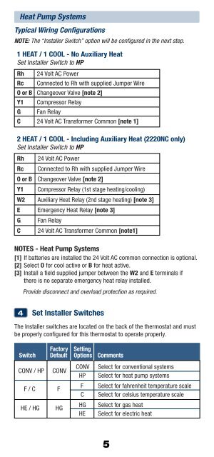
Heat Pump SystemsTypical Wiring ConfigurationsNOTE: The “<strong>Installer</strong> Switch” option will be configured in the next step.1 HEAT / 1 COOL - No Auxiliary HeatSet <strong>Installer</strong> Switch to HPRh 24 Volt AC PowerRc Connected to Rh with supplied Jumper WireO or B Changeover Valve [note 2]Y1 Compressor RelayG Fan RelayC 24 Volt AC Transformer Common [note 1]2 HEAT / 1 COOL - Including Auxiliary Heat (2220NC only)Set <strong>Installer</strong> Switch to HPRh 24 Volt AC PowerRc Connected to Rh with supplied Jumper WireO or B Changeover Valve [note 2]Y1 Compressor Relay (1st stage heating/cooling)W2 Auxiliary Heat Relay (2nd stage heating) [note 3]E Emergency Heat Relay [note 3]G Fan RelayC 24 Volt AC Transformer Common [note1]NOTES - Heat Pump Systems[1] If batteries are installed the 24 Volt AC common connection is optional.[2] Select O for cool active or B for heat active.[3] Install a field supplied jumper between the W2 and E terminals ifthere is no separate emergency heat relay installed.Provide disconnect and overload protection as required.4Set <strong>Installer</strong> SwitchesThe <strong>Installer</strong> switches are located on the back of the thermostat and mustbe properly configured for this thermostat to operate properly.SwitchCONV / HPF / CHE / HGFactory SettingDefault Options CommentsCONVCONV Select for conventional systemsHP Select for heat pump systemsFF Select for fahrenheit temperature scaleC Select for celsius temperature scaleHGHG Select for gas heatHE Select for electric heat5