SmartJoist Design Guide 2011_RGB.pdf - Tilling Timber
SmartJoist Design Guide 2011_RGB.pdf - Tilling Timber
SmartJoist Design Guide 2011_RGB.pdf - Tilling Timber

You also want an ePaper? Increase the reach of your titles
YUMPU automatically turns print PDFs into web optimized ePapers that Google loves.
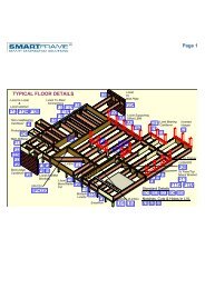
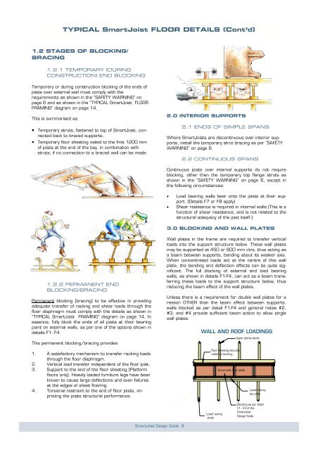
TYPICAL <strong>SmartJoist</strong> FLOOR DETAILS (Cont’d)1.2 STAGES OF BLOCKING/BRACING1.2.1 TEMPORARY (DURINGCONSTRUCTION) END BLOCKINGTemporary or during construction blocking of the ends ofjoists over external wall must comply with therequirements as shown in the “SAFETY WARNING” onpage 6 and as shown in the “TYPICAL <strong>SmartJoist</strong> FLOORFRAMING” diagram on page 14.This is summarised as:• Temporary struts, fastened to top of <strong>SmartJoist</strong>, connectedback to braced supports.• Temporary floor sheeting nailed to the first 1200 mmof joists at the end of the bay, in combination withstruts, if no connection to a braced wall can be made.2.0 INTERIOR SUPPORTS2.1 ENDS OF SIMPLE SPANSWhere <strong>SmartJoist</strong>s are discontinuous over interior supports,install the temporary strut bracing as per “SAFETYWARNING” on page 6.2.2 CONTINUOUS SPANSContinuous joists over internal supports do not requireblocking, other than the temporary top flange struts asshown in the “SAFETY WARNING” on page 6, except inthe following circumstances:• Load bearing walls bear onto the joists at their support.(Details F7 or F8 apply)• Shear resistance is required in internal walls (This is afunction of shear resistance, and is not related to thestructural adequacy of the joist itself.)3.0 BLOCKING AND WALL PLATES1.2.2 PERMANENT ENDBLOCKING/BRACINGPermanent blocking (bracing) to be effective in providingadequate transfer of racking and shear loads through thefloor diaphragm must comply with the details as shown in“TYPICAL <strong>SmartJoist</strong> FRAMING” diagram on page 14. Inessence, fully block the ends of all joists at their bearingpoint on external walls, as per one of the options shown indetails F1- F4.This permanent blocking/bracing provides:Wall plates in the frame are required to transfer verticalloads into the support structure below. These wall platesmay be supported at 450 or 600 mm ctrs, thus acting asa beam between supports, bending about its weaker axis.When concentrated loads act at the centre of this wallplate, the bending and deflection effects can be quite significant.The full blocking of external and load bearingwalls, as shown in details F1-F4, can act as a beam transferringthese loads to the support structure below, thusreducing the beam effect of the wall plates.Unless there is a requirement for double wall plates for areason OTHER than the beam effect between supports,walls blocked as per detail F1-F4 and general notes #2,#3, and #4 provide sufficient beam action to allow singlewall plates.WALL AND ROOF LOADINGSUpper storey studs1. A satisfactory mechanism to transfer racking loadsthrough the floor diaphragm.2. Vertical load transfer independent of the floor joist.3. Support to the end of the floor sheeting (Platformfloors only). Heavily loaded furniture legs have beenknown to cause large deflections and even failuresat the edges of sheet flooring.4. Torsional restraint to the end of floor joists, improvingthe joists structural performance.Floor sheeting securelynailed to blocking<strong>SmartJoist</strong> floor joistsLower storeytop plateLower storeystudsBlocking as per detailF1 - F4 of the<strong>SmartJoist</strong><strong>Design</strong> <strong>Guide</strong>.<strong>SmartJoist</strong> <strong>Design</strong> <strong>Guide</strong> 9