SmartJoist Design Guide 2011_RGB.pdf - Tilling Timber
SmartJoist Design Guide 2011_RGB.pdf - Tilling Timber
SmartJoist Design Guide 2011_RGB.pdf - Tilling Timber

You also want an ePaper? Increase the reach of your titles
YUMPU automatically turns print PDFs into web optimized ePapers that Google loves.
<strong>SmartJoist</strong><strong>Design</strong> <strong>Guide</strong>Edition 1<strong>2011</strong>
Introducing the SmartFloor ®Another first from SmartFrameNow your SmartFrame floor system can be supplied both precision docked* and with the web penetrations pre-cut to your specifications.Each joist from a SmartFrame layout comes labelled with its identifying number to match the colour A3 layout supplied as part ofthe order.This provides the builder with an industry benchmark level of information to aid quick and correct installation, and allows for easy installationof services.SmartFloor combines the speed and efficiency of <strong>SmartJoist</strong>s with the flexibility of open webbed truss systems, without the need for theinstallation of strong- backs associated with open webbed trusses.
<strong>SmartJoist</strong> ® DESIGN GUIDETABLE OF CONTENTSSCOPE and GENERAL PRODUCT INFORMATION 1ABOUT FLOOR PERFORMANCE 3RECOMMENDED MAXIMUM SPANS FOR RESIDENTIAL FLOORS 5SAFETY WARNING 6HANDLING AND STORAGE 6DURABILITY AND EXPOSURE TO MOISTURE 7GENERAL NOTES 7TYPICAL <strong>SmartJoist</strong> FLOOR DETAILSBlocking and Lateral Restraint- General Notes 8- 1.0 Joists Bearing onto Exterior Walls 8- 2.0 Interior Supports 9BLOCKING AND WALL PLATES 9<strong>SmartJoist</strong>/SmartRim CHARACTERISTIC BLOCKING CAPACITIES 10JOIST HANGER DETAILS 11GENERAL CONNECTOR INSTALLATION DETAILS 12FIELD REPAIRS TO DAMAGED <strong>SmartJoist</strong>s 13TYPICAL <strong>SmartJoist</strong> FLOOR FRAMING - General Arrangement 14TYPICAL <strong>SmartJoist</strong> FLOOR CONSTRUCTION DETAILS 14BACKER and FILLER BLOCKS 16FASTENER SPACING 17LIMITED END NOTCHING AT SUPPORTS 17FIXING TO STEEL BEAMS 17FIXING TO BRICK OR MASONRY WALLS 18TIE DOWN (BRACING WALL) DETAILS 18JOIST/BEAM CONNECTIONS SUPPORTING OFFSET LOAD BEARING WALLS 19SUPPORT FOR CONCENTRATED LOADS 20BEAMS SUPPORTING <strong>SmartJoist</strong>s - MULTIPLE MEMBER LAMINATIONS 20BRICK LEDGE CANTILEVERS 22RAFTER CUTS FOR <strong>SmartJoist</strong>s 23OBLIQUE CONNECTION OPTIONS 23<strong>SmartJoist</strong> HOLE AND DUCT CHART 24OPENINGS WITHIN SmartFrame FLOORS 27<strong>SmartJoist</strong> CANTILEVERS SUPPORTING LOAD BEARING WALLS 28<strong>SmartJoist</strong> SUPPORTING PARALLEL LOAD BEARING WALLS 29<strong>SmartJoist</strong> ROOF DETAILS 32TYPICAL <strong>SmartJoist</strong> ROOF DETAILS 33<strong>SmartJoist</strong> RAFTER TIE-DOWN 34<strong>SmartJoist</strong> RAFTER BOX GUTTER REBATE DETAILS 34SAFE LOADING OF MATERIALS ON A WORKING PLATFORM 35FIRE SAFETY AND SOUND TRANSMISSION- Fire Rated floors/ceilings 36- Sound Transmission 36SmartGuard TREATMENT 37ADHESIVE AND FORMALDEHYDE EMISSIONS 37DrillMate ® SmartSaw 38
SCOPE OF THIS PUBLICATIONThis <strong>Design</strong> <strong>Guide</strong> and Load Tables assists in the selectionof <strong>SmartJoist</strong>s for most of the common structural arrangementsmet in domestic construction. The Smart-Frame computer software, in conjunction with this manual,provides an unparalleled level of design capacity forengineered timber products.While specific details are given on suitable methods ofdeveloping lateral restraint, the methods of providing adequatesupport, adequate anchorage against wind uplift andoverall structural stability are outside the scope of thispublication.Information on the above matters can be obtained fromAS1684 Residential timber-framed construction code orfrom a structural engineer experienced in timber construction.<strong>Tilling</strong> <strong>Timber</strong> Pty Ltd has structural engineers on staffwho can be contacted for advice on matters concerningthe use of its engineered timber products in timber constructionon the SmartData Customer HelpLine on 1300668 690 or at smartdata@tilling.com.au.SUBSTITUTION OF OTHERPRODUCTSAll load tables in this document are designed using ingradetested properties for <strong>SmartJoist</strong>s as manufacturedby Pacific Woodtech Corporation of Washington State,USA. Other manufacturers I-Joists may have differentproperties and, therefore, cannot be designed using thesespan tables.COPYRIGHTCopyright of this publication remains the property of <strong>Tilling</strong><strong>Timber</strong> Pty Ltd, and reproduction of the whole or part ofthis publication without written permission from <strong>Tilling</strong><strong>Timber</strong> Pty Ltd is prohibited.CERTIFICATIONAs a professional engineer, qualified and experienced intimber engineering, I certify that the use of the <strong>SmartJoist</strong>members as shown in these tables, and installed in accordancewith the provisions of this <strong>Design</strong> <strong>Guide</strong>, willcomply with the requirements of the Building Code of Australia.These span tables have been prepared in accordancewith standard engineering principles, the relevanttest reports and Australian standards, i.e. -• AS 1684.1 Residential timber-framed construction• AS 1170.1 Structural <strong>Design</strong> Actions – PermanentImposed and other actions• AS 1720.1 <strong>Timber</strong> Structures - <strong>Design</strong> Methods• AS 4055 Wind loads for Houses• ASTM D 5055 Standard specification for establishingand monitoring structural capacities of prefabricatedwood I-JoistsCraig Kay, PEng, EC1961, RPEQ5100, BPB0730, CC5635C, NPERNational Product Manager - EWPWeb thickness 44, 51 58 and 70 mm flanges: 9.5 mm, 90 mm flanges: 11.5 mm342003434 34 34 34240 240 240 24030044 40 51 70 9040SJ20044 SJ24040 SJ24051 SJ24070 SJ24090SJ30040<strong>SmartJoist</strong> sizes available in each state may vary from time to time. Check you local stockist before ordering343834300343003430034360360400517090589090SJ30051SJ30070SJ30090SJ36058SJ36090SJ40090<strong>SmartJoist</strong> dimension tolerances: depth: +0 -3 mm, Flange width: +/- 1 mm, flange thickness: no plus limitation -2 mm.<strong>SmartJoist</strong> <strong>Design</strong> <strong>Guide</strong> 1
THE STRENGTH IS INTHE ENGINEERINGThe SmartFrame Engineered <strong>Timber</strong> System is made up of:• World class engineered timber products:i. <strong>SmartJoist</strong>sii. SmartLVL'siii. SmartLam Glulamiv.Unique Structural <strong>Design</strong>, Detailing and EstimatingSoftware• Full engineering support and technical advice from experiencedengineers and field staff free of charge on ourunique SmartData Customer HelpLine 1300 668 690<strong>SmartJoist</strong>s.The strength is in the engineering:- Strong. Stiff. Reliable.<strong>SmartJoist</strong>s are engineered for heavy performance. We startwith ultrasonically graded LVL, bonded with exterior adhesivefor more load carrying capacity.The webs are made from stable, strong Oriented Strand Board(OSB) for superior strength and consistent performance.<strong>SmartJoist</strong>s are more uniform than solid sawn joists. They staystraighter and are manufactured with no camber, so there isno chance of crown down or upside down installation. Theyresist shrinking, twisting, warping and splitting for squeak resistantfloors and quality roofs and ceilings.Holes may be easily cut in the web according to the tables onpage 22, allowing ducts and utilities to be run through thejoists. Pre-punched 40 mm knockout holes are provided in theweb for small diameter services or wiring.Save Time and Money:- Because they weigh less than solidsawn joists, <strong>SmartJoist</strong>s are easier to install, saving constructiontime and cost. Their greater load carrying capacity allowsyou to space them further apart, so it takes fewer to build theaverage floor or roof. And with five (5) depths from 200 to400 mm, you will never have to compromise your design. Sowhether your plans call for cantilever beams in balconies, cathedralroofs or high pitched roof slopes, <strong>SmartJoist</strong>s are theperfect choice.An Environmentally Sound Choice:- In addition to being costeffective, <strong>SmartJoist</strong>s are also an environmentally soundchoice because they are made of a renewable resource –wood. So they are a better choice for building.<strong>SmartJoist</strong>s have a certified Chain of Custody system toPEFC.SmartFrame Software:- Our unique SmartFrame design, detailingand estimating software offers you unparalleled design andestimating capabilities with engineered timber. You will getaccurate designs for a wide variety of applications, printoutsand joist layouts.Limitations of use - <strong>SmartJoist</strong>s.<strong>SmartJoist</strong>s are to be used in dry interior environments only,fully enclosed from exposure to exterior moisture. <strong>SmartJoist</strong>sare suitable for subfloor applications provided that the subfloorspace is ventilated as per the BCA requirements. This meansthat <strong>SmartJoist</strong>s must not be exposed to environments wherethe equilibrium moisture content of the joist will exceed 18%.<strong>Tilling</strong> <strong>Timber</strong> will not guarantee <strong>SmartJoist</strong>s that have beenleft exposed to the weather either prior to or during constructionfor more than 90 days.Detailing such as cladding or lining must be used in moistureladen environments (commercial kitchens, bathrooms, wetindustrial areas, saunas, swimming pool and spa rooms etc.)and constructed in such a way as to prevent exposure of the<strong>SmartJoist</strong> to moisture.<strong>SmartJoist</strong>s may be used in applications which are often exposedexternally (gable ends, eaves, floor joists applications inelevated houses, cantilevered joists etc.) but must be sufficientlyenclosed with a suitable cladding, lining etc. to completelyprevent the exposure of the <strong>SmartJoist</strong> to moisture.SmartFrame Consumer Product Warranty<strong>Tilling</strong> <strong>Timber</strong> guarantees that SmartFrame Engineered <strong>Timber</strong> products have been manufacturedto exacting standards and are free from defects in workmanship and materials.At <strong>Tilling</strong> <strong>Timber</strong>, we take great pride in SmartFrame products, so if you bring to our attentionproblems such as squeaks that you believe are caused by our products, we guarantee that atechnical representative will contact you promptly to evaluate the issues and provide advice tohelp solve the problemProviding that any SmartFrame product is correctly designed, handled and installed, any problemcaused by an unlikely defect will promptly be remedied at no cost to you.This guarantee remains valid for the expected life of your home.<strong>Tilling</strong> <strong>Timber</strong> – Proudly Australian owned and operated.Priority call: 1300 668 690 e-mail: smartdata@tilling.com.au<strong>SmartJoist</strong> <strong>Design</strong> <strong>Guide</strong> 2
GENERAL INFORMATION - ABOUT FLOOR PERFORMANCEThe “feeling” that is identified when a person walks on afloor is very subjective. Some people want to feel a verystiff floor and others want some ”give” so that it softensthe footing. When people say the floor “bounces”, it maybe vibrating. This sensation is often caused by lack of deadload such as furniture, direct applied ceilings or other materialsto absorb or dampen the vibration.The allowable spans shown in the tables of this manualhave been designed to meet the strength and serviceabilitycriteria in AS1684.1. This standard introduced a furtherserviceability equation into the design of floor joists whichchecked the deflection caused by a 1.0 kN load applied atmid-span. If the differential deflection of the joist relative toan adjacent joist exceeds 2.0 mm then the span isdeemed to be such that the floor performance may beconsidered too bouncy for service.FACTORS THAT CAN AFFECT FLOORDYNAMIC PERFORMANCE.• The choice of flooring system• The depth, stiffness and mass of the joists• Spacing of joists• Fixing of sheathing to joists• Stiffness and mass of floor sheathing• Mass and stiffness of ceiling materials• Method of installation• Location and type of internal partitions and furnitureFACTORS THAT CAN IMPROVEFLOOR DYNAMIC PERFORMANCE.• Glue-nailed floors will perform better than floors securedby nails alone.• Deflection of the sheathing material between joistscan be reduced by decreasing the joist spacing orusing a thicker and/or stiffer sheathing.• Proper installation is essential for dependable performance.Adequate and level support for the joists isnecessary, as is correct fastening of the joists andsheathing.• The installation of a ceiling to the bottom flange of thejoists.• Between joist blocking can provide some improvementto floor dynamic performance. It is emphasised thatfor between joist blocking to be effective, it is importantthat the blocking is continuous, this beingeasily achieved by the addition of a continuous bottomstrap such as hoop iron strapping which is also attachedto the end walls.If floor dynamic performance is a concern to either theclient, designer or contractor, then the above variablescan be altered to improve dynamic performance. Somestiff floors with very little dead load may tend to vibrate.This can generally be dampened by directly attaching theceiling below the underside of the joists. Where there is nolining to the underside of the joists, it is recommendedthat between joist blocking be utilised to dampen this lightweightfloor.If between joist blocking is to be used to improve floor dynamicperformance, it is recommended that a blockingsystem (at least midspan, ⅓ points for large open rooms)similar to the one shown below should be adopted.BETWEEN JOIST BLOCKING FOR <strong>SmartJoist</strong>sFloor sheeting glued AND nailedto joists and blocking<strong>SmartJoist</strong> between joist blocking,skew nailed with 2.8 x 60 mm nails.0.91 x 25 mm galvanised mild steel strapfastened to joists, blocking panels and ENDWALLS with 40 x 2.5 mm galvanised nails.<strong>SmartJoist</strong>floor joists<strong>SmartJoist</strong> <strong>Design</strong> <strong>Guide</strong> 3
<strong>SmartJoist</strong> DESIGN/EFFECTIVE SPANNormal structural analysis uses the centreline representation of the member. The term “span” can be defined in a number of ways andthese are defined as follows:Clear Span. This is the distance between the faces of any support. It is generally the one easiest to measure and read from the drawingsNominal span/centre-line span. This is the distance between the centre of the supports. This span is used to determine bendingmoments and deflections for continuous spaning <strong>SmartJoist</strong> members<strong>Design</strong> span/Effective span. This is the span used for single span members to determine the bending moment, the slenderness ofbending members and the deflections. In AS 1720.1, this is the dimension referred to as “L”, and is defined below.<strong>Design</strong> span/Effective span is the distance between -• The centre of the bearing at each end of a beam where the bearing lengths have NOT been conservatively sized• The centre of notional bearing that have been sized appropriately, where the size of the bearing IS conservative.Diagram (a) shows beam where bearings have been designed appropriately. The effective span is taken as the distance between thecentre of each bearing areaClear span (Distance between face of supports)Effective span (design span L)Diagram (b) shows beam where bearings at each end have been oversized. (This is frequently the case for beams that bear onto brickworkor concrete walls where the thickness of the wall is in excess of the area required to give the beam bearing capacity).To find the correct effective span:1. Calculate the minimum bearing required to carry the loads satisfactorily2. Add minimum bearing length to “clear span” distanceEffective span (design span) LClear span (Distance between face of supports)Centre-line span (distance betweeen centres of supports)Area of supportrequired forbearingLength of effective bearing<strong>SmartJoist</strong> <strong>Design</strong> <strong>Guide</strong> 4Length oforiginalbearing(oversized)
RECOMMENDED MAXIMUM SPANS FOR RESIDENTIAL FLOORSGENERAL DOMESTIC - 1.5 kPaLoadings: Permanent Loading G: self weight + 40 kg/m 2 + 0.6 kPa of live load permanently applied, live load Q: 1.5 kPa or 1.8 kN point live loadJoist spacing (mm) 300 400 450 600 300 400 450 600<strong>SmartJoist</strong> CodeSelf weight(kg/m)Single spanMaximum floor Joist span (mm)Continuous spanSJ20044 2.8 4700 4350 4100 3700 5450 5000 4900 4350SJ24040 3.0 5100 4750 4600 4200 5950 5500 5350 4900SJ24051 3.4 5400 5000 4900 4500 6300 5800 5650 5200SJ24070 4.0 5800 5400 5200 4850 6700 6200 6000 5500SJ24090 5.0 6150 5700 5600 5100 7200 6650 6450 5950SJ30040 3.4 5900 5400 5300 4900 6800 6300 6100 5650SJ30051 3.9 6200 5700 5600 5150 7200 6650 6450 5900SJ30070 4.3 6600 6100 6000 5500 7600 7100 6800 6300SJ30090 5.5 6950 6500 6300 5900 8150 7550 7300 6700SJ36058 4.8 7150 6600 6500 6000 8300 7700 7400 6900SJ36090 5.9 7700 7200 7000 6500 9050 8400 8100 7500SJ40090 6.2 8150 7500 7300 6900 9600 8900 8650 7800In compiling the span tables in this manual, the requirements of the relevant Australian standards and codes along with establishedIndustry standard design guidelines for Residential Construction have been followed. In particular, the following codes and referenceshave been used:• AS 1684.1 Residential timber-framed construction• AS 1170.1 Structural design actions – permanent imposed and other actions• AS 1720.1 <strong>Timber</strong> Structures - design methods• AS 4055 Wind loads for houses• AS/NZS 4063 Characterization of structural timber• ASTM D 5055 Standard specification for establishing and monitoring structural capacities of prefabricated wood I-JoistsSERVICEABILITY CRITERIA:Max dead load deflection - lesser of span / 300 or 15 mm (j 2 = 2)Max live load deflection - lesser of span / 360 or 9 mmFLOOR DYNAMIC PERFORMANCE CRITERIA:Minimum Natural Frequency - 8 HertzMaximum differential deflection between Joists of 2 mm under a concentrated load of 1.0 kN mid-span.FLOORING:Spans are suitable for solid timber, particle board and ply flooring. Floor sheathing glued and nailed to the joists will improve floor rigidity.Where a heavy overlay material is to be applied, such as thick mortar bed tiled or slate floors, the permanent load allowance shouldbe increased to 1.2 kPa. A reduction of joist spacing can be used to accommodate this extra permanent load. A satisfactory result canbe achieved by adopting the maximum spans for 600 mm and 450 mm spacings but installing the joists at 450 mm and 300 mmspacings respectively.CONTINUOUS SPANS:For beams which are continuous over two unequal spans, the design span and the "resultant span description" depend on the percentagedifference between the two spans as shown below:Span differenceEffective spanResultant span description10% max main span continuous10 - 30% 1.1 x main span continuousabove 30% diff main span singlespan difference =(main span - second span)(main span + second span)X 100Main spanSecond span<strong>SmartJoist</strong> <strong>Design</strong> <strong>Guide</strong> 5
SAFETY WARNINGDO NOT ALLOW WORKERS OR LOADSON <strong>SmartJoist</strong>s UNTIL ALL BLOCKING,HANGERS, RIM JOISTS, NAILING ANDTEMPORARY BRACING ARE IN-STALLED AS SPECIFIED BELOW. SERI-OUS ACCIDENTS OR INJURY CAN RE-SULT FROM FAILURE TO FOLLOW THE-SE GUIDELINES.ACCIDENTS CAN BE AVOIDEDUNDER NORMAL CONDITIONS BYFOLLOWING THESE GUIDELINES:1. Brace each joist as it is erected. Joists must benailed to supports and all hangers, blocking, rimjoists. X - bridging at supports must be completelyinstalled and properly nailed. (see general notesand details)2. Brace the ends of cantilevers (overhangs) withclosure panels, rim joist or x - bridging (see generalnotes and details)3. Lateral brace the top flange of each joist, to preventsideways buckling or rollover which may occurunder light construction loads, such as a workerand/or a layer of un-nailed sheathing. Fully installedpermanent sheathing or temporary struts to thetop flange of each joist (see ‘Typical <strong>SmartJoist</strong>floor framing’) can accomplish lateral bracing. Temporarystruts must be nailed to a lateral restraintat the end of bay such as a braced wall or temporary(or permanent) sheathing nailed to the first1200 mm of the joist at the end of the bay (see‘Typical floor or roof framing’)4. Permanent sheathing must be completely installedand properly nailed before additional loads can beplaced on the system5. The integrity and safe use of these productscan be seriously impaired if they are damaged.Do not install any damaged products. Contactyour <strong>Tilling</strong> representative or the SmartDataCustomer HelpLine on 1300 668 690 if anyproduct damage is noted.HANDLING AND STORAGE OF <strong>SmartJoist</strong>s• Store <strong>SmartJoist</strong>s flat on a hard, dry surface• If surface isn't paved, the ground should becovered with a polythene film• Keep covered with waterproof material thatallows bundles to "breathe"• Use bearers (bolsters) between the groundand the first bundle (4 metre max spacing)• Use 100 x 50 timber flat between bundlesat same spacing as bolsters• Take great care to rewrap remaining materialafter opening bundles• Wood "grows" in thickness and depth whenallowed to get wet....KEEP DRY!• Wood with high MC has short term reductionin Characteristic Strengths …. KEEPDRY!• Under NO circumstances are stored<strong>SmartJoist</strong>s to be in contact with theground.Bearers at amaximum of 4000mm centresUse bearers to keep stacked material away from damp surfaces.Align bearer vertically<strong>SmartJoist</strong>s should be stacked in theupright position to avoid any damage<strong>SmartJoist</strong> <strong>Design</strong> <strong>Guide</strong> 6
DURABILITY AND EXPOSURE TO MOISTURE<strong>SmartJoist</strong>s are manufactured with Douglas Fir (Oregon)flanges with OSB webs, both having a durability rating ofclass 4, which is the same rating as some Ash type Eucalypts.Untreated <strong>SmartJoist</strong>s should not be used wherethe equilibrium moisture content is likely to remain above18 % for an extended period.Untreated <strong>SmartJoist</strong>s are suitable in the internal, fullyprotected, ventilated and the external above ground, protectedzones of the structure as shown in appendix B ofAS 1684. Untreated <strong>SmartJoist</strong> is not suitable for externalabove ground, exposed or humid indoor conditions,such as swimming pool enclosures.The wood fibre in <strong>SmartJoist</strong>s, like all wood products, ishygroscopic, which means it has an affinity for water. Thewood fibre in <strong>SmartJoist</strong> will readily take up and releasemoisture in response to changes in the local environment.Moisture exposure will lead to dimensional change. Whilethe products will withstand normal exposure, excessiveexposure during distribution, storage or construction maylead to dimensional changes that affect serviceability. Thesechanges include twisting, bowing or expansion to dimensionsto beyond the specified tolerance of the product inthe “as-manufactured” condition.As an organic material, mold and mildew may grow onuntreated wood products if moisture is present. Prolongedperiods of high moisture may also support the growth ofwood decay fungi, which is another reason to follow propermethods of storage and handling of <strong>SmartJoist</strong>s.The table below shows the moisture content of<strong>SmartJoist</strong>s as a function of humidity.Moisture content of wood products % (1)MOISTURE EFFECTS ON<strong>SmartJoist</strong>s<strong>SmartJoist</strong> is supplied WITHOUT any short term constructionsealer, but once framed into a structure maybe exposed to the weather for a limited time (not greaterthan 3 months) without negative affect, BUT, it mayexhibit some effects of this exposure.Relative Humidity % LVL Flange MC OSB web10 1.2 0.820 2.8 1.030 4.6 2.040 5.8 3.650 7.0 5.260 8.4 6.370 11.1 8.980 15.3 13.190 19.4 17.2(1). Approximate moisture content at 21 0 CWetting during construction may lead to temporary elevatedmoisture content and dimensional changes. Once covered,the <strong>SmartJoist</strong>s will ultimately dry and re-equilibrateto the ambient humidity conditions, but some expansion orswelling may remain after drying.<strong>SmartJoist</strong>s - GENERAL NOTESDo NOT start toe nailinto the corner of the flangeor the top of the flange.MAXIMUM Nail diameter 3.15 mmNails should be as faras practical from theend of the joistStart toe nailapproximately 2/3up the side of the flange.1. Except where otherwise noted, 30 mm minimum bearingis required at joist ends and 42 mm minimum bearingis required at intermediate supports.2. Nail joists at each bearing with 2 of 3.15 Ф x 65 nails,using one each side placed 30 mm from the end toavoid splitting.3. <strong>SmartJoist</strong> blocking or SmartRim - face nail to bearingplate with 3.15 Ф x 65 nails at 150 mm centres. Nailrim joist to the end of the top and bottom flange of each<strong>SmartJoist</strong> with 1 3.15 Ф x 65 nail, use 1 3.75 Ф x75 nail top and bottom with joists with 58, 70 or 90<strong>SmartJoist</strong> <strong>Design</strong> <strong>Guide</strong> 7mm wide flanges.4. 19 mm SmartRim - toe nail to bearing plate with 3.15Ф x 65 nails at 150 centres or 4.5 Ф x 75 nails at 300centres. Nail rim to the end of the top and bottomflanges of each <strong>SmartJoist</strong> with 1 3.15 Ф x 65 nails.5. Sheathing nailing to top flange (Joists must be fullybraced before sheathing is nailed)- Space 2.8 Ф x 65 and 3.15 Ф x 65 nails no closerthan 50 mm per row.- Space 3.75 x 75 nails no closer than 75 mm.Maximum nail spacing: 300 mm
<strong>SmartJoist</strong>s - GENERAL NOTES (Cont’d)6. Backer blocks at hanger details:40 mm flanges - 15 mm ply44 & 51 mm flange - 19 mm ply58 mm flange - 2 pieces of 12 mm ply70 mm flange - 2 pieces of 15 mm ply90 mm flange - 2 pieces of 19 mm ply7. See double <strong>SmartJoist</strong> detail F15 for filler blocks. Nail Joiststogether with two rows of 3.75 Ф x 75 nails on each side ofdouble joist at 300 mm centres (Clinch if possible). A total of4 nails per 300 mm is required. If nails can be clinched, only2 nails per 300 mm is required.8. All joists require lateral support at end bearings using blockingor rim material.9. The top flanges must be kept straight within 10 mm of thetrue alignment.10. See web stiffener detail F13 for web stiffener attachment atsupports. Web stiffener requirements for concentratedloads in excess of 4.5 kN, applied at the top flange of thejoist, requires additional consideration.11. When required, install web stiffeners to joist (see detail F13)prior to placing joist in the hanger, then nail hanger to joist.12. All roof details are valid to a maximum angle of 35° (as perAS168413. All nails are steel nails complying with AS 2334 - 1980 Steelnails - Metric series. Nail gun nails of similar length and diametermay be substituted for the above provided that theyare manufactured with properties equivalent to the nails inthe above code.14. Install all hangers to the manufacturers installation instructions,taking particular attention to the use of the correctnails. Never use clouts or brads.15. Prescriptive code requirements for mid span blocking of solidtimber joists are not applicable to <strong>SmartJoist</strong>s.TYPICAL <strong>SmartJoist</strong> FLOOR DETAILSBLOCKING AND LATERALRESTRAINTGENERAL NOTES:<strong>SmartJoist</strong>s designed and constructed as per this <strong>Design</strong> <strong>Guide</strong>do not require mid-span blocking. The exception to this is forlightweight subfloors where there is no lining to the underside ofthe joists. For more information on this topic, see page 3‘ABOUT FLOOR PERFORMANCE’.Blocking within a structure falls within two (2) quite distinctstages:Temporary or during construction blocking to prevent roll overof joists before the installation of floor sheeting.Permanent blocking to provide resistance to racking loadsthrough the floor diaphragm, transfer of vertical wall loads andto provide torsional resistance to the end of the joist.The provision contained within AS1684 Residential timberframedconstruction code dealing with blocking for deep joists,is “during construction” or “temporary” blocking, designed onlyto prevent the roll over of the deep joists prior to the floorsheeting being attached. This level of blocking can form a partof any overall blocking system, but was never intended toprovide the total amount of racking resistance or vertical loadtransfer requirements within this floor diaphragm.Further, as a holistic approach to the consideration of the lateralstability of the complete structure, it is necessary to considerthe availability of racking and shear resistance through thefloor diaphragm.1. Racking and shear effects due to wind and earthquakeloads2. Vertical loads on joists due to upper wall, floors androof.The lateral bracing requirements of the structure, unless thereis full blocking of exterior walls, must be calculated in each individualcase. Advice on this matter is obtainable from AS1684Residential timber-framed construction code.1.0 JOISTS BEARING ONTOEXTERNAL WALLS1.1 LOADS AT JOIST/SUPPORTCONNECTIONThe ends of floor joists that bear onto a support experienceexternal loads other than the floor dead and live loads, asshown. Any I-Joist, with it’s small cross sectional area, needs tohave its end bearing capacity considered as part of the designprocess.3. Unsightly deflections in the edges of unsupported sheetflooring may be experienced if heavy items of furnitureare placed close to sheet edges.<strong>SmartJoist</strong> <strong>Design</strong> <strong>Guide</strong> 8
TYPICAL <strong>SmartJoist</strong> FLOOR DETAILS (Cont’d)1.2 STAGES OF BLOCKING/BRACING1.2.1 TEMPORARY (DURINGCONSTRUCTION) END BLOCKINGTemporary or during construction blocking of the ends ofjoists over external wall must comply with therequirements as shown in the “SAFETY WARNING” onpage 6 and as shown in the “TYPICAL <strong>SmartJoist</strong> FLOORFRAMING” diagram on page 14.This is summarised as:• Temporary struts, fastened to top of <strong>SmartJoist</strong>, connectedback to braced supports.• Temporary floor sheeting nailed to the first 1200 mmof joists at the end of the bay, in combination withstruts, if no connection to a braced wall can be made.2.0 INTERIOR SUPPORTS2.1 ENDS OF SIMPLE SPANSWhere <strong>SmartJoist</strong>s are discontinuous over interior supports,install the temporary strut bracing as per “SAFETYWARNING” on page 6.2.2 CONTINUOUS SPANSContinuous joists over internal supports do not requireblocking, other than the temporary top flange struts asshown in the “SAFETY WARNING” on page 6, except inthe following circumstances:• Load bearing walls bear onto the joists at their support.(Details F7 or F8 apply)• Shear resistance is required in internal walls (This is afunction of shear resistance, and is not related to thestructural adequacy of the joist itself.)3.0 BLOCKING AND WALL PLATES1.2.2 PERMANENT ENDBLOCKING/BRACINGPermanent blocking (bracing) to be effective in providingadequate transfer of racking and shear loads through thefloor diaphragm must comply with the details as shown in“TYPICAL <strong>SmartJoist</strong> FRAMING” diagram on page 14. Inessence, fully block the ends of all joists at their bearingpoint on external walls, as per one of the options shown indetails F1- F4.This permanent blocking/bracing provides:Wall plates in the frame are required to transfer verticalloads into the support structure below. These wall platesmay be supported at 450 or 600 mm ctrs, thus acting asa beam between supports, bending about its weaker axis.When concentrated loads act at the centre of this wallplate, the bending and deflection effects can be quite significant.The full blocking of external and load bearingwalls, as shown in details F1-F4, can act as a beam transferringthese loads to the support structure below, thusreducing the beam effect of the wall plates.Unless there is a requirement for double wall plates for areason OTHER than the beam effect between supports,walls blocked as per detail F1-F4 and general notes #2,#3, and #4 provide sufficient beam action to allow singlewall plates.WALL AND ROOF LOADINGSUpper storey studs1. A satisfactory mechanism to transfer racking loadsthrough the floor diaphragm.2. Vertical load transfer independent of the floor joist.3. Support to the end of the floor sheeting (Platformfloors only). Heavily loaded furniture legs have beenknown to cause large deflections and even failuresat the edges of sheet flooring.4. Torsional restraint to the end of floor joists, improvingthe joists structural performance.Floor sheeting securelynailed to blocking<strong>SmartJoist</strong> floor joistsLower storeytop plateLower storeystudsBlocking as per detailF1 - F4 of the<strong>SmartJoist</strong><strong>Design</strong> <strong>Guide</strong>.<strong>SmartJoist</strong> <strong>Design</strong> <strong>Guide</strong> 9
<strong>SmartJoist</strong>/SmartRim ® CHARACTERISTIC BLOCKING CAPACITIESSmartRim ®SmartRim rimboard is an alternative solution to blocking with<strong>SmartJoist</strong>s (either long length of cut to length) to supportvertical and lateral wall loads as part of a floor or roof framingsystem.SmartRim is a 19 mm LVL (2 veneers are cross laminated forstability) and is sold in 3.6 m lengths, precision ripped tomatch the height of the <strong>SmartJoist</strong> range up to and including360 mm. (400 mm SmartRim in QLD only). Fixing of rimboardis described in detail in <strong>SmartJoist</strong>—GENERAL NOTES item 3on page 7 of this <strong>Design</strong> <strong>Guide</strong>.SmartRim has a joint strength group of JD4 on the wide facefor nails, screws and bolts.<strong>SmartJoist</strong>/SmartRim CHARACTERISTIC CAPACITY VALUES(see notes below)Vertical load capacity(1) (2)(kN/m)Horizontal load transfer capacity(3) (4)(kN/m)63 6.91. Vertical load capacity above is for instantaneous load conditions and mustbe multiplied by the appropriate k 1 factor for load condition under consideration2. Vertical load capacity above already includes the k12 factor for up to 400mm depth as per clause I2.3 of AS 1720.13. Horizontal load capacity above is an instantaneous load condition, with thek1 for lateral bracing loads usually 1.04. The above horizontal load capacity is limited by the fixing of the<strong>SmartJoist</strong> /SmartRim to the frame and can ONLY be achieve if the fixingdetail on page 7 of this <strong>SmartJoist</strong> <strong>Design</strong> <strong>Guide</strong> is strictly adhered to.PENETRATIONS WITHIN <strong>SmartJoist</strong> and SmartRimThe maximum allowable hole size for a <strong>SmartJoist</strong>/SmartRimshall be ⅔ of the rim board depth as shown below.The length of the <strong>SmartJoist</strong>/SmartRim segment containing ahole shall be at least 8 times the hole size.<strong>SmartJoist</strong> HOLE SIZES AND MINIMUM LENGTH<strong>SmartJoist</strong>/SmartRimDepth (mm)Maximum allowable hole size (a) (b) (mm)Minimum length of <strong>SmartJoist</strong>/SmartRim board segment(c) for the maximum allowable hole size (mm)200 130 1050240 160 1280300 200 1600360 235 1900400( d) 265 2100(a)(b)(c)These hole provisions do not apply to <strong>SmartJoist</strong>/SmartRim installed over openings such as doors or windowsThe diameter of the round hole or the longer dimension of the rectangular holeThe lengths of the <strong>SmartJoist</strong>/SmartRim segment per wall line. For multiple holes, the minimum length of <strong>SmartJoist</strong>/SmartRim segment shall be 8 times the sum of allhole sizesApplication Notes.1. Do not cut holes in SmartRim installed over openings, suchas doors or windows, where the SmartRim is not fully supported,except that holes of 40 mm or less in size are permittedprovided they are positioned at the middle depth and in themiddle ⅓ of the span ( see note 5 for minimum hole spacing).2. Field-cut holes should be vertically centred in SmartRim andat least one hole diameter or 150 mm whichever is less, cleardistance away from the end of the wall line. Holes should neverbe placed such that they interfere with the attachment of therim board to the ends of the floor joist, or any other coderequirednailing.3. While round holes are preferred, rectangular holes may beused providing the corners are not over-cut. Slightly roundingcorners or pre-drilled corners with a 25 mm diameter bit isrecommended.SmartRim OVER AN OPENINGDo not cut holes in SmartRim over an opening except for holesof 40 mm or less in size (see note 1).Top plateSmartRim<strong>SmartJoist</strong>/SmartRim NEAR CONCENTRATEDVERTICAL LOAD4. When concentrated loads are present on the <strong>SmartJoist</strong>/SmartRim (loads not supported by any other vertical-loadcarryingmembers such as squash blocks), holes should not beplaced in the <strong>SmartJoist</strong>/SmartRim within a distance equal tothe depth of the <strong>SmartJoist</strong>/SmartRim from the area of loading.HH min2/3 H MaxTop plate5. For multiple holes, the clear spacing between holes shall beat least two times the diameter of the larger hole, or twice thelength of the longest rectangular hole. This minimum hole spacingdoes not apply to holes of 40 mm or less in diameter, whichcan be placed anywhere in the rim board (see note 1 for holesover opening) except that the clear distance to the adjacent holeshall be 75 mm minimum.MULTIPLE HOLES FOR <strong>SmartJoist</strong>/SmartRim6. All holes shall be cut in a workman-like manner in accordancewith the limitations listed above.Hole of 40 mmor lessd1d2 < d1Door or window opening75mmMinMin 2 x d1<strong>SmartJoist</strong> <strong>Design</strong> <strong>Guide</strong> 10Top plate
JOIST HANGER DETAILSNAILINGUse only the listed galvanised bracket nails. All holes are to be filled with the specified nails in order to achieve the statedhanger capacity. Alternatively, screw with 35 x 6 gauge bugle-head or wafer-head wood screws. The joist hangers belowhave been developed specifically for <strong>SmartJoist</strong>s. The joist hangers and nails are available from <strong>Tilling</strong> <strong>Timber</strong> as part of aSmartFrame order. It is not recommended that joist hangers other than those listed below be used with <strong>SmartJoist</strong>s.<strong>SmartJoist</strong>s brackets in areas shaded require web stiffeners as per detail F13<strong>SmartJoist</strong>face mountcodehangercapacityΦkN *face nailholesnail sizetop mountcodehangercapacityΦkN *face nailholes tosupporttop nailholesnails tojoistnail sizeSingle joist face mountsSingle joist top mountSJ20044 20044F 6.2 8 3.75 x 40 20044T 4.8 2 4 2 3.75 x 40SJ24040 24040F 7.8 10 3.75 x 40 24040T 4.8 2 4 2 3.75 x 40SJ24051 24051F 7.8 10 3.75 x 40 24051T 4.8 2 4 2 3.75 x 40SJ24070 24070F 7.8 10 3.75 x 40 24070T 4.8 2 4 2 3.75 x 40SJ24090 24090F 7.8 10 3.75 x 40 24090T 4.8 2 4 2 3.75 x 40SJ30040 30040F 9.3 12 3.75 x 40 30040T 4.8 2 4 2 3.75 x 40SJ30051 30051F 9.3 12 3.75 x 40 30051T 4.8 2 4 2 3.75 x 40SJ30070 30070F 9.3 12 3.75 x 40 30070T 4.8 2 4 2 3.75 x 40SJ30090 30090F 9.3 12 3.75 x 40 30090T 4.8 2 4 2 3.75 x 40SJ36058 36058F 10.9 14 3.75 x 40 36058T 4.8 2 4 2 3.75 x 40SJ36090 36090F 10.9 14 3.75 x 40 36090T 4.8 2 4 2 3.75 x 40SJ40090 40090F 10.9 14 3.75 x 40 40090T 4.8 2 4 2 3.75 x 40Double joist face mountsDouble joist top mounts2/SJ20044 20044DF 6.2 8 3.75 x 40 N/A2/SJ24040 N/A 24040DT2/SJ24051 24051DF 7.8 10 3.75 x 40 24051DT 4.8 2 2 4 3.75 x 402/SJ24070 24070DF 7.8 10 3.75 x 40 24070DT 4.8 2 2 4 3.75 x 402/SJ24090 24090DF 7.8 10 3.75x40 24090DT 5.7 2 4 2 3.75 x 402/SJ30040 N/A N/A2/SJ30051 30051DF 8.7 12 3.75 x 40 30051DT 4.8 2 2 4 3.75 x 402/SJ30070 30070DF 8.7 12 3.75 x 40 30070DT 4.8 2 2 4 3.75 x 402/SJ30090 30090DF 8.7 12 3.75 x 40 30090DT 5.7 2 4 2 3.75 x 402/SJ36058 N/A 36058DT 4.8 2 4 2 3.75 x 402/SJ36090 N/A 36090DT 5.7 2 4 2 3.75 x 40Skewed left or right (face mount)<strong>SmartJoist</strong>SmartFrame codehangercapacityΦkN *face nailholesNails to joistnail sizeSJ20044 20044FR or FL 6.2 8 2 3.75 x 40SJ24040N/ASJ24051 -SJ30051240-30051FR or FL 6.2 8 2 3.75 x 40SJ24070N/ASJ24090 24090FR or FL 6.2 8 2 3.75 x 40SJ30040N/ASJ30051 30051FR or FL 7.8 10 2 3.75 x 40SJ30090 30090FR or FL 7.8 10 2 3.75 x 40SJ36058 36058RR or FL 7.8 10 2 3.75 x 40SJ36090 36090FR or FL 7.8 10 2 3.75 x 40ALL LVSIA 5.5 4 112 g x 35screwVariable Slope (face mount - usually for rafters)NOTES:<strong>SmartJoist</strong>SmartFramecodehangercapacityΦkN *face nailholesNails to joistnail sizeSJ20044 20044VS 4.6 10 7 3.75 x 40SJ24051 - SJ30051240-30051VS4.6 10 7 3.75 x 40SJ24070 - SJ30070 N/ASJ24090 - SJ40090240-40090VS9.9 18 12 3.75 x 40SJ36058 36058VS 4.6 10 7 3.75 x 40* Hanger capacity is based upon dead load + floor live load for a supporting beam of joint strength JD5.k 1 = 0.69, Capacity factor Ø = 0.85. For permanent loads, the above value should be multiplied by 0.57/0.69 = 0.82.<strong>SmartJoist</strong> <strong>Design</strong> <strong>Guide</strong> 11
GENERAL CONNECTOR INSTALLATION DETAILSPOSITIVE ANGLE NAILING TOP MOUNT HANGERSCORRECTNAILINGPREVENT ROTATIONNAIL ATWRONG ANGLENAIL TOO LONGHANGER OVER SPREADIf hanger is overspread, I-Joistmay be raised above header,also, NO support for top flange.HANGER NOT PLUMBA hanger kicked out fromthe header can causeuneven surfaces.Hangers provide some joist rotation resistance; however, additional lateral restraint may be required for deep joists.CORRECT FASTENERSNO WEB RESISTANCERESULTS IN ROTATIONI-JOIST HEADERSNO WEB STIFFENERREQUIREDHanger side flange supportsjoist top flange.D60%of DMINWEB STIFFENER REQUIREDHanger side flange should beat least 60% of joist depth orpotential joist rotation must beaddressed.Backer blocking each side, hanger nails must extend past thesupporting joist's web member into the backer blocking.Bracket capacities arebased upon using thecorrect bracket nail asper the table on page11. Bracket nails havespecial heads to providestrength. Clouts, bradsetc are NOT suitable asbracket nailsFACE MOUNTCONNECTION TO WEBBottom flange pulling off whenBacker block on one side only.The top flange of the supporting joist must be supportedby backer blocks to prevent cross grain bending and rotation.TOP MOUNTCONNECTION<strong>SmartJoist</strong> <strong>Design</strong> <strong>Guide</strong> 12
FIELD REPAIRS TO DAMAGED <strong>SmartJoist</strong>sDON’T MAKEHOLES WITHHAMMER OTHERTHAN PRE-PUNCHEDKNOCKOUTSDON’THAMMER ONFLANGES ANDDAMAGE JOINTDO NOT CUT OR NOTCH FLANGESDO NOT OVER-CUT HOLES IN WEB<strong>SmartJoist</strong>s are sophisticated Engineered <strong>Timber</strong> products, and must be treated accordingly. Damage to keycomponents, while affecting only a small percentage of the cross section may be sufficient to render the<strong>SmartJoist</strong> unsuitable for the purpose.It is therefore recommended that damage to joists and the possibility of repair be referred to the SmartDataCustomer Helpline on 1300 668 690 or at smartdata@tilling.com.au for advice.FLANGE DAMAGE• Flange damage becomes more critical the nearer it is tomid-span or an interior support. Flange damage is lesscritical in close proximity to an end support.• How much flange damage is acceptable? A rule ofthumb is "If you have to ask, it's too much". A saw kerfthat knicks the corner of a flange on one lightly-loadedjoist could well be acceptable.• A joist with unacceptable flange damage cannot be repaired,rather a new joist must be added to take it'splace. The damaged joist does not have to be removed.Consult <strong>SmartJoist</strong> and SmartLVL tables to find an acceptablenew joist that is shallower than the damagedjoist so installation is easier. Consider double and triplejoists. If the damaged joist is multi-span, the new joistonly needs to go across the span(s) where the damageoccurs.• A single damaged joist can sometimes be trimmed off ofadjacent undamaged joists (run a calculation within theSmartFrame software).WEB DAMAGE• Web damage becomes more critical the nearer a support.Web damage is less critical near mid-span.• Web holes can be too big to repair. A flange-to-flangerectangular hole longer than 450 mm located at midspanprobably warrants a new joist. A 150 mm roundhole located right by a support probably warrants a newjoist. Consult <strong>SmartJoist</strong> and SmartLVL tables to find anacceptable new joist that is shallower than the damagedjoist so installation is easier. Consider double and triplejoists. If the damaged joist is multi-span, the new joistonly needs to go across the span(s) where the damageoccurs.• A single damaged joist can sometimes be trimmed off ofadjacent undamaged joists (run a calculation within theSmartFrame software)• Damage that could be confidently repaired in a single,isolated joist, might be judged too severe to repair ifseveral, adjacent joists are involved• If several small holes violate the 2x diameter proximityrule, but would fit inside a single acceptable hole, thenthe group of small holes is OK• Hole repairs generally require a reinforcement that coversthe full depth of the web and extends at least 300mm past each side of the hole.DAMAGE REPORT INFORMATIONREQUIRED1.In order to design a repair, the SmartFrame engineerwill have to know all of the design information that isrequired to run SmartFrame software.2.Provide a sketch of the damage showing it's size, shapeand location on the joist.3.Indicate whether a pipe, duct, conduit, etc. must remainand be accommodated.4.Indicate how many adjacent joists are affected in eachcase.FIELD REPAIRS TO DAMAGED <strong>SmartJoist</strong> WEBSThe SmartFrame system now includes the WebFix ® (webreinforcement) developed to be a rapid “repair” to webswhere penetrations have been placed at inappropriate locations,penetrations too large or other web damage whichdiminishes the strength of the member. This repair systemis unique to <strong>SmartJoist</strong> applications.<strong>Tilling</strong> <strong>Timber</strong> is the SOLE Australian distributor of this PA-TENTED system, which in most cases can be fixed aroundservices that have been installed through the web penetrations.The WebFix ® does need to be designed into each situationby SmartFrame engineers and can ONLY be purchasedfrom <strong>Tilling</strong> offices after the structural design is completed.<strong>SmartJoist</strong> <strong>Design</strong> <strong>Guide</strong> 13
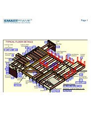
TYPICAL <strong>SmartJoist</strong> FLOOR FRAMINGF7 or F8<strong>SmartJoist</strong> blocking panel or full depth cripple on eachside required when supporting load bearing walls above.Nonload-bearingcantileverF9Blocking panelsrequired when<strong>SmartJoist</strong>s arecantileveredF2<strong>SmartJoist</strong> rim joistHole sizes and locationsas per hole chartsC1 or C2Load bearing cantileverF1&F5<strong>SmartJoist</strong>BlockingF15Approved joisthangerF12Standardconnectionof I-Joist toI-JoistsMultiple<strong>SmartJoist</strong>sSolid timberor LVL BeamF3& F4SmartRimRimboardF11Standard connection of<strong>SmartJoist</strong> to solidtimber or LVL beam.Temporary floor sheeting if end wall isnot braced. Attach with 3.15 mm dianails at 150 mm centres Max. Keep inposition until permanent sheeting isinstalled. (see #2 of SAFETY WARNING)Temporary struts at 2400 mm centres.Nail struts to each joist with 2 of 3.15 mm diam x 65 nails.TYPICAL <strong>SmartJoist</strong> FLOOR CONSTRUCTION DETAILS<strong>SmartJoist</strong>blockingpanel<strong>SmartJoist</strong>rim joistButt sections togetherat centre of lowerstorey stud.F1F2SmarRimRimboard(2 layers forground floorof a 2 storeybuilding)F4Load-bearing wallJoistsBearerNOTE:Top plate width must be greaterthan width of flange rim joist +30 mm (min bearing length)F32 layers ofSmartRimRimboardSmall section ofbearer materialplaced onstumps/piers tosupport joistssupporting parallelload-bearing walls.F5Solid block all postsfrom above tobearing below.CONCENTRATED ROOF LOADSNote:To achieve the necessary racking resistance through the floordiaphragm, it is important that the nailing provisions of thefloor sheeting to the joists as described in AS 1684 (AS 1869for particle board) be adopted to nail the floor sheeting to the<strong>SmartJoist</strong> <strong>Design</strong> <strong>Guide</strong> 14
TYPICAL <strong>SmartJoist</strong> FLOOR CONSTRUCTION DETAILS (Cont’d)Backer for claddingattachment.F6Use doublejoists underwall wherevertical loadexceeds29 KN/mWARNING - CORRECT BLOCKINGFOR <strong>SmartJoist</strong>sGREEN TIMBER SHALL NOT BE USEDUNDER ANY CIRCUMSTANCE.All blocking shall be carried out as per details F1-F3, withblocking to extend to both flanges and skew nailed with3.15 Ф x 65 nails, one each side of top and bottom flange.<strong>SmartJoist</strong> shall be designedto support load bearing wallabove when not stacked overwall below.INTERIOR LOAD BEARING AND BRACING WALLSLoad bearing wallabove must stackover wall below2 mm<strong>SmartJoist</strong>blockingPanelF7F8NOTE: Detail F7 with blocking panel is required for bracing walls.90 X 45 F5Cripple skewnailed to bothflanges with3.15 x 65 nails.NON LOAD-BEARING CANTILEVER DETAILS (BALCONIES)Example cantilever spans and minimum back spans for this detail are shown in the table on the next page<strong>SmartJoist</strong> blockingNon Load bearing wall to amaximum height of 2400 mm200 x 50 mm Min. Nail to backer block & joist with 2 rows of 3.15 dia x 75 mmat 150 mm centres and clinchA70 mmMIN.Bearing.F9Min F8 - Durable ortreated timber(UNIFORM LOADS ONLY).1200 mm MAX. 1200 mm MIN.L1.5 x LNon Load bearing wallto a maximum heightof 2400 mmABacker block - Nail with 2 rows of3.75 dia x 65 mm nails at 150 centresand clinchSection A-AUNIFORM LOADS ONLY<strong>SmartJoist</strong> blockingNOTE: <strong>SmartJoist</strong>sMUST BE PROTECTEDFROM THE WEATHER<strong>SmartJoist</strong>s may be cantilevered up to 1/3of their back span.L/3 MAX.Example 1200 mmLExample: 3600 mmFOR CANTILEVERS SUPPORTING LOAD BEARING WALLS, SEE DETAILS C1 or C2.<strong>SmartJoist</strong> <strong>Design</strong> <strong>Guide</strong> 15
.CANTILEVERED BALCONIES as per detail F9Loadings: Permanent Loading G: self weight + 40 kg/m 2 + 0.6 kPa of live load permanently applied,live load Q: 2.0 kPa or 1.8 kN point live load , 1.5 kN/m acting at end of cantileverBalcony Cantilevers - Maximum cantilever and minimum back span (m)Joist spacing (mm) 300 400 450 600Cantilever material Cantilever Back span Cantilever Back span Cantilever Back span Cantilever Back spanH3 SmartFrame LVL 15150 x 42 1.0 1.5 1.0 1.5 1.0 1.5 0.9 1.4170 x 42 1.2 1.8 1.1 1.7 1.1 1.7 1.1 1.7200 x 42 1.4 2.1 1.3 2.0 1.3 2.0 1.3 2.0240 x 42 1.7 2.6 1.6 2.4 1.6 2.4 1.5 2.3300 x 42 2.1 3.2 2.0 3.0 2.0 3.0 1.9 2.9H3 MGP 10140 x 45 0.7 1.1 0.7 1.1 0.7 1.1 0.7 1.1190 x 45 1.1 1.7 1.1 1.7 1.1 1.7 1.1 1.7240 x 45 1.5 2.3 1.4 2.1 1.4 2.1 1.4 2.1BACKER and FILLER BLOCKSBacker block, nailwith 10 of 3.75 diax 75 nails.F10If the sides of the hanger do not supportthe top flange, Web stiffeners as perDetail F13 are required.F11Filler blockingnail with 10 of3.75 x 75 nailsF12HangerFiller block,nail with 10 of3.75 dia x 75 nailsSolid timberor LVL beamNail backer blocking Backer blockwith 10 of 3.75 x 75 nails. requiredFILLER BLOCKS AND WEB STIFFENERS<strong>SmartJoist</strong>codeRecommendedfiller blockWeb stiffener materialstiffenernailsSJ20044 120x35 15x60 mm ply 4-3.15x65SJ24040 140x35 15x60 mm ply 4-3.15x65SJ24051 140x45 19x60 mm ply 4-3.15x65SJ24070 150x58 LVL 2/15x60 mm ply 4-3.15x65SJ24090 2/140x45 2/19x60 mm ply 5-3.15x65SJ30040 190x35 15x60 mm ply 4-3.15x65SL30051 190x45 19x60 mm ply 4-3.15x65SJ30070 150x58 LVL 2/15x60 mm ply 4-3.15x65SJ30090 2/190x45 2/19x60 mm ply 5-3.15x65SJ36058 250x50 2/12x60 mm ply 5-3.15x65SJ36090 2/240x45 2/19x60 mm ply 5-3.15x65SJ40090 2/240x45 2/ ply 5-3.15x65WEB STIFFENERSF1350 mm ±NOTES :1.Use plywood sheathingfor web stiffener withface grain parallel to50 mm ±long axis of the stiffener.2.Filler blocks noted arefor the general requirementsof the detailswithin this design guide.3.Leave 3 mm gap betweentop of filler blocksand bottom of topflange.Small Gap( 3mm ± )Nails, 4 of 3.15x 65, ClinchedTight FitDO NOT bevel cutjoist beyondinside face of wall.F14DOUBLE <strong>SmartJoist</strong>sGap asper F130F153.75 x 75 nails at300 mm spacing.(Offset nails from oppositeface by 150 mm )Continuous fillerNOTE:<strong>SmartJoist</strong> blocking or timber X - bracingrequired at bearing for lateral support.1. Support back of web during nailing to prevent damage to web/flange connection2. Filler block is required full length of joist3. Nail Joists together with two rows of 3.75 Ф x 75 nails on eachside of double joist at 300 mm centres (Clinch if possible). A total of4 nails per 300 mm is required. If nails can be clichéd, only 2 nailsper 300 mm is required.<strong>SmartJoist</strong> <strong>Design</strong> <strong>Guide</strong> 16
FASTENER SPACINGMinimum single row nail spacing into <strong>SmartJoist</strong> flangesOffset secondrow of nailingMinimum nailspacingfrom table<strong>SmartJoist</strong> flange widthnail size 40 mm 44 mm 51 mm flange 58-70 mm2.8 x 65 7065 50 503.15 x 65 100 90 75 753.15 x 75 100 90 75 753.75 x 75 130 115 100 1004.5 x 100 NA 1 NA 1 NA 1 NA 190 mm flange507575100100NOTES:1. Nailing of bottom plate at 100 mm centres through floor sheathing and into top flange is permitted2. Minimum nail spacing is shown above, maximum nail spacing is set by the flooring manufacturer, inabsence of manufacturers data, 300 mm centres3. Tighter effective nail spacing may be obtained by offsetting nail rows a minimum of 12 mm and maintaininga 10 mm minimum edge distance.LIMITED END NOTCHING AT SUPPORTSThe cutting of notches in the ends of joists may reduce the allowable end reactions of the <strong>SmartJoist</strong>sThe amended end reaction capacities of <strong>SmartJoist</strong>s with a 12 mm notch are as follows:• Without web stiffeners - 80% of allowable end reaction• With added web stiffeners (as per detail F13) - Full end reaction capacity. Web stiffener installedin contact with bottomflange as per detail F133-4 mm gap betweentop of web stiffenerand top flangeF16UB, UC orChannelSectionDO NOT OVER CUT FLANGES. SUBSTANTIALREDUCTIONS IN CAPACITY MAY OCCUR IFFLANGES ARE OVER CUT.Rebate of12 mm MaxMin bearinglength 35 mmAdequate lateral restraintor alternatively, a 10 x 30mm long type 17 screw tolower flangeTo maintain the end reaction capacities above, end flange notching is strictly limited to:1. Notch depths NOT greater than 12 mm2. Notches cleanly cut - NO over cutting3. Notch length not to exceed more than 5 mm past the support.EXAMPLE FIXING OF <strong>SmartJoist</strong>s TO STEEL BEAMSTOP MOUNT HANGERone bracket nailin every holeof the joist hanger.Coach boltsFixing platebolted to steelsheet flooringF17UB, UCor Channelsection<strong>SmartJoist</strong><strong>SmartJoist</strong>Joist hanger tomatch joist size.<strong>SmartJoist</strong> <strong>Design</strong> <strong>Guide</strong> 17Top mountjoist hangerUB, UC, PFCor Channelsection
EXAMPLE FIXING OF <strong>SmartJoist</strong>s TO STEEL BEAMS (Cont’d)F18DWeb stiffener installedin contact with bottomflange as per detail F135 - 6 mm gapFACE MOUNT HANGERFiller block depthmust fit all facemount nails (min20 mm edge distance)Min bearinglength 30 mmLOWER FLANGE BEARINGweb notch to bethe min necessaryfor clearance.D/2 (Max)20 mm (MAX)UB, UCor Channel SectionProvide lateral restraint(e.g blocking) to lower flangeor alternatively 1/No 10 x 30mm type 17 screw.May be rebated as perDetail F16.70 mm verticalsoftwood packerat bolt locations<strong>SmartJoist</strong>2 of 3.15 x 65 mmnails, one each side,a minumum of 30mm from the end<strong>Timber</strong> packer,minimum of 45 mmbearing to steeland timber I-JoistF18A22 mmmaximumrebateUBsteel beamPacker to be securelyfastened to steel beamEXAMPLE FIXING OF <strong>SmartJoist</strong>s TOBRICK OR MASONRY WALLSF19fixing plates: sizedependent upon<strong>SmartJoist</strong> and steelbeam sizes, but notless than 25 mmbearing onto steelbeamMin of one M12 bolt every 1200 mm centres and not less than3 bolts per filler block section, staggered where possible.Min edge and end distance of 60 mm.F20joist hangerBrick or masonry wallMasonry anchors to engineersdesign and installed tomanufacturer's recommendations.Smart LVL or similarplate, depth to approxmatch joist depth.TIE DOWN (BRACING WALL) DETAILSThe tie-down needs of the structure are related to the applied wind loads. Reference should be made to AS 1684 for furtherguidance on this issue. The general details relating to the tie-down provisions of solid end section timber may be adopted for<strong>SmartJoist</strong>s, except that under NO circumstances is it permitted to bolt through either the top or bottom flange, exceptwhen the joist is fully supported upon a wall plate or similar as shown below.Seasoned timberblocking piece90Bracing (Tie Down) wallM10 bolt90 x 45 seasoned timber bridging cleat.Cleats to be placed no closer than 1500 mm.NOTE : CHARACTERISTIC UPLIFT CAPACITY 11.9 kNSeasoned timberblocking pieceNails to locate bridging cleatagainst top flange as shown.<strong>SmartJoist</strong>F21Bracing (Tie Down) wallDO NOT DRILLTHROUGHEITHERFLANGE OF<strong>SmartJoist</strong>sunless they arefully supportedon wall plateor similarF21AM12 boltFB65170 Joist hangers (both upand down) with 18 off 35 x 3.15 mmGalvanised <strong>Timber</strong> Connector Nailsinto web stiffeners/joist web.17 mm (min) F11 Ply, Min of 170 mmwide. Nail with 4 off 4.5 x 75 nails andclinch. Fit flush under top flange of<strong>SmartJoist</strong>It is important that this beam is nailed into joist hangers toprevent joists spreading under loadMin 170 x 58 SmartLVL 15 bridging cleat. Cleat spacing to begoverned by Joist strength calculations with applied uplift loads.NOTE: MAX force transfer of system 30.0 kN(It is essential that <strong>SmartJoist</strong> is analysed for these extreme loads)<strong>SmartJoist</strong> <strong>Design</strong> <strong>Guide</strong> 18
Load bearing wallCyclone rodCYCLONE ROD TIE DOWN FORCANTILEVERED<strong>SmartJoist</strong> FLOORSWeb stiffenersas per page 16Max distance fromcyclone rod to webstiffener of 100 mm.Floor sheeting<strong>SmartJoist</strong>blockingpanelCyclone rod,nut and washerunder plateWeb stiffeners required eachside of ALL joists withcyclone tiesCyclone rod, nut andwasher under top plateCS1CYCLONE STRAP CAPACITIESWhere the strap ends of thecyclone strap are wrappedaround the wall plate or othertimber member and are fixedwith 4 of 3.15 Ø x 35 nails,the design capacity ØN j of 15.3 kN is applicable, regardlessof the timber joint group. Tests have proven that bendingthe legs of cyclone straps around the timber increases theultimate load capacity.Prydacyclonestrap orequivalentCantileverSpanEqual to cantileverspan but MIN of600 mm.While double joists shown in the above diagram, it is onlynecessary when loads exceed the capacities of single joistcantilevers.JOIST/BEAM CONNECTIONS SUPPORTING OFFSET LOADBEARING WALLSModern building designs frequently call for the upper storey of a two storey dwelling to be set back from the lower wall toallow sufficient light access to all areas of the building. Provided that the <strong>SmartJoist</strong>s have been designed to support thisoffset load, no special provisions need to be made for their support EXCEPT in the following support conditions:BrickormasonrywallRA1Load bearing wallLoadbearingwallRA2UB, UC orChannelSectionUB, UCor ChannelsectionJoist hanger to match joist size.Joist spanRebate of12 mm MaxJoist spanMin bearinglength 35 mmMaximum Roof Area Supported (m 2 )- based upon worst case of 40 mm flange width (conservative for wider flanged joists)Joist supported on joist hanger RA1Lower flange bearing RA2Joist spacing300 400 450 600 300 400 450 600 300 400 450 600 300 400 450 600(mm)Joist spanSheet Tile SheetTile(mm)3500 21.7 15.0 12.8 8.2 9.6 6.7 5.7 3.6 6.9 6.4 6.2 5.3 3.1 2.9 2.8 2.44000 21.1 14.5 12.3 6.9 9.4 6.4 5.5 3.1 6.7 6.2 6.0 4.6 3.0 2.8 2.7 2.04500 20.5 13.9 11.7 5.7 9.1 6.2 5.2 2.5 6.6 6.0 5.7 3.9 2.9 2.7 2.5 1.75000 20.0 13.4 10.4 4.4 8.9 5.9 4.6 2.0 6.4 5.8 5.1 3.1 2.9 2.6 2.3 1.45500 19.4 12.1 9.1 3.2 8.6 5.4 4.1 1.4 6.3 5.3 4.6 2.4 2.8 2.4 2.0 1.1<strong>SmartJoist</strong> <strong>Design</strong> <strong>Guide</strong> 19
SUPPORT FOR CONCENTRATED LOADS - JOIST/BEAMCONNECTIONS SUPPORTING OFFSET LOAD BEARING WALLSConcentrated loads from anysource such as girder trussesMUST be transferred through thefloor space WITHOUT adding extravertical loads to the ends of the<strong>SmartJoist</strong> at its bearing support.One example of transferring theseloads is the use of inclined timberstruts as shown in the detail opposite.Struts must be a tight fit andat a minimum angle of 60 º to thehorizontalRA3Skew nail 2 of 3.15 x 75 mmnails through to lower plate70 x 35 F5 nailed tounderside of top flange ofadjacent joists with3.15 x 60 nails90 x 45 F5 strut underconcentrated load. Numberof struts to match numberof members in jamb stud orpost.Studs or postssupporting TruncatedGirder truss or otherconcentrated roofloadsRebate of12 mm MaxMin bearinglength 38 mmWeb stiffeneras per detailF13UB, UC orChannelSectionBEAMS SUPPORTING <strong>SmartJoist</strong>s –MULTIPLE MEMBER LAMINATIONSVertical laminations may be achieved by adopting the proceduresdescribed in clause 2.3 of AS1684, howeverthese procedures should be considered as the minimumrequirements to achieve the desired effect.Experience with SmartLVL beams indicates that this degreeof fixing may not satisfactorily prevent cupping ofindividual components as a result of the ingress of moisturebetween laminates during construction. The suggestedmethod of vertical lamination below provides a greaterlevel of fixity between individual components, and with theuse of an elastomeric adhesive, also prevents moisturepenetration between the laminates.MULTIPLE MEMBER LAMINATINGOF TOP LOADED BEAMS(Symmetrical loading)The edges of the individual sections must be carefullyaligned to each other so that the composite beam is flat,allowing the applied loads to be equally shared.• Depths up to and including 300 mm: 2 rows ofnails as shown above at 300 mm centre• Depths in excess of 300 mm: 3 rows of nails asshown above at 300 mm centresNails driven on alternate sides300 mm spacingTemporaryWaterproofmembraneBead ofElastomericadhesiveD300 mm spacingBead ofElastomericadhesive<strong>SmartJoist</strong> <strong>Design</strong> <strong>Guide</strong> 20
MULTIPLE MEMBER LAMINATING OF SIDE LOADED BEAMS(Non– symmetrical loading)Combination 1 Combination 2 Combination 32 pieces of35 or 42 mm3 pieces of35 or 42 mm1 piece of 35 or 42 mm1 piece of 58 or 75 mmNail spacing50 mm Min50 mmMinBolt spacing50 mm MinStagger row of bolts55 mm diameterwasher as per table4.12 - AS 1720.150 mm MinMAXIMUM FLOOR LOAD WIDTH SUPPORTED BY EITHER OUTSIDE MEMBER (mm)Combination(see details above)3.75Ф x 90 mm nails 12 mm Ф bolts2 rows at 300ctrs3 rows at 300ctrs2 rows at 600 ctrs2 rows at 300ctrsCombination 1 3400 5100 7500 15000Combination 2 2900 4000 5600 11000Combination 3 2900 4000 4500 11000Notes:1. Table values are for 40 kg/m 2 floors.2. The table values for nails may be doubled for nails at 150 mm centres, and tripled for nails at 100 mm centres3. The nail schedules shown apply to both sides of a three (3) piece beam4. Bolts are to be grade 4.6 commercial bolts conforming to AS 1111. Bolt holes are to be a maximum of 13 mm diameter and are to belocated NOT less than 50 mm from either edge.5. All bolts shall be fitted with a washer at each end, of a size NOT less than that given in AS 1720.1 table 4.11.HOW TO USE THE MAXIMUM UNIFORM SIDELOAD TABLEExample: see diagram oppositeFloor load width 1 Floor load width 2= 2800 mm = 2300 mmBeam of 2 SmartLVL loaded on both side (Combination 1)FLW 1 = 2800 mm, FLW 2 = 2300 mmTotal FLW = 2800 + 2300 = 5100 mm.1. Use SmartFrame software or SmartLVL safe load tables to size the twomember section to support the FLW of 5100 mm.2. Choose the larger of the side FLW's carried by the beam, in this case 2800mm.3. Enter the table at the "Combination 1" row and scan across to a table valuegreater than 2800 mm. The first value in the row at 3600 mm is greaterthan the 2800 mm required.4. Thus adopt 2 rows of 3.75Ф x 90 mm nails at 300 mm centres<strong>SmartJoist</strong> <strong>Design</strong> <strong>Guide</strong> 21
BRICK LEDGE CANTILEVERS CONSTRUCTION DETAILSCantilevered <strong>SmartJoist</strong>s as “brick ledge cantilevers” (Max of160 mm cantilever) to suit upper storey clad frames DO NOTusually require any special modification (other than the necessarytimber or ply/LVL closure member attached to the outeredge as shown in details C1 or C2. The exceptions to this arewhere concentrated floor loads (e.g. truncated girders, jambstuds) are supported on anIndividual cantilevered joist such that the concentrated roof loadarea supported exceeds that as shown below for an unreinforced<strong>SmartJoist</strong>.Individual joists may be reinforced, if required, as per detailsF23 or F24 to support a roof load area (measured in squaremetres) as shown below.Un-reinforced <strong>SmartJoist</strong> Web Filler (F23) Reinforcing one side (F24)Sheet Roof Tiled Roof Sheet Roof Tiled Roof Sheet Roof Tiled RoofJoist spacing (mm) 300 450 600 300 450 600 300 450 600 300 450 600 300 450 600 300 450 600<strong>SmartJoist</strong>Roof area supported (m 2 )SJ20044 8.8 7.1 5.4 5.1 4.2 3.2 12.2 10.5 8.8 7.2 6.2 5.2 10.2 8.6 6.9 6.0 5.0 4.0SJ24040 9.7 8.0 6.3 5.7 4.7 3.7 13.1 11.4 9.7 7.7 6.7 5.7 11.1 9.4 7.7 6.5 5.5 4.5SJ24051 10.6 8.6 6.9 6.0 5.0 4.1 13.7 12.0 10.3 8.0 7.0 6.1 11.8 10.1 8.4 6.9 5.9 4.9SJ24070 14.2 13.2 12.2 8.3 7.6 6.9 15.6 14.5 13.3 9.1 8.5 7.8 17.6 16.4 15.2 10.3 9.6 8.9SJ24090 17.9 16.2 14.5 10.5 9.5 8.5 21.3 19.6 17.9 12.5 11.5 10.5 19.3 17.6 15.9 11.3 10.3 9.3SJ30040 9.6 8.0 6.3 5.6 4.7 3.7 13.1 11.4 9.7 7.6 6.7 5.7 11.1 9.4 7.7 6.5 5.5 4.5SJ30051 10.3 8.6 6.9 6.0 5.0 4.0 13.7 12.0 10.3 8.0 7.0 6.0 13.6 12.3 11.2 8.0 7.2 6.6SJ30070 13.7 12.4 11.2 8.0 7.3 6.6 18.9 17.6 16.4 11.1 10.3 9.6 17.2 15.8 14.6 10.0 9.3 8.6SJ30090 17.8 16.2 14.5 10.4 9.5 8.5 21.3 19.6 17.9 12.4 11.5 10.5 19.3 17.6 15.9 11.3 10.3 9.3SJ36058 12.9 11.2 9.5 7.5 6.5 5.5 16.3 14.6 12.9 9.5 8.5 7.6 14.3 12.6 10.9 8.4 7.4 6.4SJ36090 17.8 16.1 14.4 10.4 9.4 8.5 21.2 19.6 17.9 12.4 11.4 10.5 19.3 17.6 15.9 11.3 10.3 9.3SJ40090 17.8 16.1 14.4 10.4 9.4 8.4 21.2 19.5 17.9 12.4 11.4 10.5 19.3 17.6 15.9 11.3 10.3 9.3SmartRim closureas per Detail C1 or C2F22Between Joist blocking -I-Joist, or SmartRim3.7 x 75 mm nails,1 each side,Load bearingstud wall.Between Joist blockingas per F1, alternativematerial, SmartRimSmartRim closure asper detail C1 and C2SmartRim orPlywood web fillers(WHERE REQUIRED)Load BearingStud Wall.REINFORCING GUIDELINES(a) USING WEB FILLERSBrick veneerlower storeywall.50 mm Minfrom end of joist300 mmMinLeave smallgap approx 6 mmSmartRim or ply webfillers, both sidesTRIMMER JOISTS WHERE MAIN JOISTS RUNPARALLEL TO BRICK LEDGE CANTILEVER WALL.Nail web filler with2 rows of 3.75 x 65nails , clinched.Use SmartLVLsupport joist to match<strong>SmartJoist</strong> depths.Between Joist blocking -I-Joist, or SmartRim3.7 x 75 mmnails, 1 each sideF25F24160 mm Max(b) USING REINFORCING (one side)300 mmMinF23SmartRim or Ply reinforcing.NOTE: For 360 and 400deep Joists, web fillers arerequired with reinforcement.SmartRim web fillers(WHERE REQUIRED)Loadbearingstud wall.Trimmer Joists to be MINIMUM of600 mm from inside of bearingplate to support LVL floor Joist.50 mm Min fromend of joist160 mm MaxNail reinforcementwith 2 rows of3.75 x 65 nails,clinched.<strong>SmartJoist</strong> <strong>Design</strong> <strong>Guide</strong> 22
RAFTER CUTS FOR <strong>SmartJoist</strong>s<strong>SmartJoist</strong>s can be “rafter cut” but only within the limitation shown below.Rafter cuts are limited to:1) 115 mm MINIMUM end height2) MINIMUM Roof Slopes of 1 in 2 (approximately 26.5 0 ),and3) Must be blocked at the end to prevent rotation of the joist.Joists without reinforcement are limited to design shear and end reactions up to 6.5 kN Ply reinforcement can be added tojoists with rafter cuts to increase the shear and end reaction capacity of the joist. The detail below shows the proper installationof the reinforcement. With the reinforcement added, the end reaction and shear capacity increase to 12.7 kNDuration of load increases are permitted as per AS1720.1.F2621 MINTop flange must bebraced either bysheeting or 100 x 50for lateral stability.115 mm MINBlocking600 mm19 mm F11 Ply or SmartRim. Installreinforcement to both sides of joist usingadhesive meeting AS/NZS 4364:1996and nail using 14 of 3.75 x 75 mm evenlyspaced as shown. Alternate nailing fromeach side and clinch.90 mmMin bearingOBLIQUE CONNECTION OPTIONSF27SmartLVL Bearer/Waling plateSkew nail top flange with3.15 x 65 mm nail toBearer/Waling plateFix angle plate tobearer or waling platewith 4 No 12 x 45 mmType 17 Hexagonalhead screws5.0 mm dia holecountersunkto underside4 of 7.0 mmdia holesMin distancefrom bothedges 10 mm2037515050MinNotch bottom ofjoist for a flushfinish, as perdetail on page 17Fix <strong>SmartJoist</strong> to angleplate with a 10 x 30 mmlong type 17counter-sunk screw75 x 50 x 5 Unequal Angle150 mm long support, longLeg vertical - SEE ADJACENTDETAIL.Min thickness ofbearer/waling plate45 mmNOTE:It is recommended that the FL/FR joisthangers as shown on page 6 be used formembers at 45° to the support. Formembers at angles other than 45°, theVS (variable skew) brackets or the LVSIAbracket shown here may be used.<strong>SmartJoist</strong> <strong>Design</strong> <strong>Guide</strong> 23
<strong>SmartJoist</strong> HOLE AND DUCT CHARTSDON’TMAKE HOLESWITH HAMMEROTHER THANPRE-PUNCHEDKNOCKOUTSDON’THAMMER ONFLANGES ANDDAMAGEJOINTDO NOT CUT OR NOTCH FLANGESDO NOT OVER CUT HOLES IN WEBMinimum Distance from Hole chartMinimum Distance from hole chartWidth 'W'See Note 7Depth 'D'Note 3A 40 mm dia hole may becut anywhere in the webWidth 'W'Do not cut holeslarger than 40 mmdia within thecantileverNote: The most accurate method to design the allowable web penetration size and distance from support for <strong>SmartJoist</strong>s is to use the SmartFrame software.The table below will give conservative results in some instances. Also, advice on hole size and location may be obtained by contacting the SmartDataCustomer Helpline on 1300 668 690 or at smartdata@tilling.com.au.LOAD ASSUMPTION (DL = 62 kg/m 2 , FLL = 2 kPa, FPL = 1.8 kN)Circular/square holesRectangular holesJoist codeJoist span (mm)Joistspacing(mm)Hole diameter/Square hole width (mm)Depth x Width (mm)75 100 125 150 175 200 225 250 125x150 150x300 175x350 200x400Minimum distance from any support to the centre of the hole (mm)600-999300 300 ns ns ns ns ns ns ns ns ns ns1000-1499 300 300 ns ns ns ns ns ns ns ns ns nsSJ200441500-1999 300 300 ns ns ns ns ns ns ns ns ns ns300 to 6002000-2499 300 600 ns ns ns ns ns ns ns ns ns ns2500-2999 300 800 ns ns ns ns ns ns ns ns ns ns3000-3300 300 900 ns ns ns ns ns ns ns ns ns ns600-999300 300 300 ns ns ns ns ns ns ns ns ns1000-1499 300 300 300 ns ns ns ns ns ns ns ns nsSJ240401500-1999 300 300 300 Span/2 ns ns ns ns 750 Span/2 ns ns300 to 6002000-2499 300 300 300 Span/2 ns ns ns ns 1000 Span/2 ns ns2500-2999 300 300 500 Span/2 ns ns ns ns Span/2 Span/2 ns ns3000-3500 300 300 800 Span/2 ns ns ns ns Span/2 Span/2 ns ns600-999300 300 300 ns ns ns ns ns ns ns ns ns1000-1499 300 300 300 ns ns ns ns ns ns ns ns ns1500-1999 300 300 300 Span/2 ns ns ns ns 750 Span/2 ns nsSJ240512000-2499 300 to 600 300 300 300 Span/2 ns ns ns ns 1000 Span/2 ns ns2500-2999 300 300 500 Span/2 ns ns ns ns Span/2 Span/2 ns ns3000-3499 300 300 800 Span/2 ns ns ns ns Span/2 Span/2 ns ns3500-3800 300 300 1000 Span/2 ns ns ns ns Span/2 Span/2 ns ns600-999300 300 300 ns ns ns ns ns ns ns ns ns1000-1499 300 300 300 ns ns ns ns ns 300 ns ns ns1500-1999 300 300 300 Span/2 ns ns ns ns 600 Span/2 ns nsSJ240702000-2499 300 300 300 Span/2 ns ns ns ns 900 Span/2 ns ns300 to 6002500-2999 300 300 500 Span/2 ns ns ns ns 1250 Span/2 ns ns3000-3499 300 300 800 Span/2 ns ns ns ns 1500 Span/2 ns ns3500-3999 300 300 1000 Span/2 ns ns ns ns Span/2 Span/2 ns ns4000-4100 300 450 1100 Span/2 ns ns ns ns Span/2 Span/2 ns ns<strong>SmartJoist</strong> <strong>Design</strong> <strong>Guide</strong> 24
<strong>SmartJoist</strong> HOLE CHARTS (Cont’d)LOAD ASSUMPTION (DL = 62 kg/m 2 , FLL = 2 kPa, FPL = 1.8 kN)Circular/square holesRectangular holesJoist codeJoist span(mm)Joist spacing(mm)Hole diameter/square hole width (mm)Depth x Width (mm)75 100 125 150 175 200 225 250 125x150 150x300 175x350 200x400Minimum distance from any support to the centre of the hole (mm)600-999300 300 300 ns ns ns ns ns ns ns ns ns1000-1499 300 300 300 ns ns ns ns ns 300 ns ns ns1500-1999 300 300 300 700 ns ns ns ns 500 750 ns nsSJ240902000-2499 300 300 300 1000 ns ns ns ns 800 1000 ns ns300 to 6002500-2999 300 300 400 1150 ns ns ns ns 1100 Span/2 ns ns3000-3499 300 300 700 1400 ns ns ns ns 1400 Span/2 ns ns3500-3999 300 300 800 1550 ns ns ns ns 1700 Span/2 ns ns4000-4100 300 300 900 1600 ns ns ns ns 1800 Span/2 ns ns600-999300 300 300 300 300 300 ns ns 300 300 ns ns1000-1499 300 300 300 300 300 300 ns ns 300 500 Span/2 ns1500-1999 300 300 300 300 300 500 ns ns 300 Span/2 Span/2 Span/2SJ300402000-2499 300 300 300 300 300 700 ns ns 500 Span/2 Span/2 Span/2300 to 6002500-2999 300 300 300 300 400 1000 ns ns 900 Span/2 Span/2 Span/23000-3499 300 300 300 300 600 1200 ns ns 1300 Span/2 Span/2 Span/23500-3999 300 300 300 300 900 1450 ns ns 1750 Span/2 Span/2 Span/24000-4100 300 300 300 400 1000 1500 ns ns Span/2 Span/2 Span/2 ns600-999300 300 300 300 300 300 ns ns 300 300 ns ns1000-1499 300 300 300 300 300 300 ns ns 300 500 Span/2 ns1500-1999 300 300 300 300 300 500 ns ns 300 750 Span/2 Span/2SJ300512000-2499 300 300 300 300 300 700 ns ns 400 Span/2 Span/2 Span/2300 to 6002500-2999 300 300 300 300 400 1000 ns ns 800 Span/2 Span/2 Span/23000-3499 300 300 300 300 600 1200 ns ns 1200 Span/2 Span/2 Span/23500-3999 300 300 300 300 900 1450 ns ns 1600 Span/2 Span/2 Span/24000-4300 300 300 300 400 1000 1600 ns ns 1800 Span/2 Span/2 ns600-999300 300 300 300 300 300 ns ns 300 300 ns ns1000-1499 300 300 300 300 300 300 ns ns 300 500 Span/2 ns1500-1999 300 300 300 300 300 500 ns ns 300 750 Span/2 Span/22000-2499 300 300 300 300 300 700 ns ns 400 1000 Span/2 Span/2SJ300702500-2999 300 to 600 300 300 300 300 400 950 ns ns 700 1250 Span/2 Span/23000-3499 300 300 300 300 600 1200 ns ns 1000 Span/2 Span/2 Span/23500-3999 300 300 300 300 900 1450 ns ns 1400 Span/2 Span/2 Span/24000-4499 300 300 300 500 1100 1700 ns ns 1800 Span/2 Span/2 Span/24500-4600 300 300 300 700 1200 1800 ns ns 1900 Span/2 Span/2 Span/2600-999 300 300 300 300 300 300 ns ns 300 300 ns ns1000-1499 300 300 300 300 300 300 ns ns 300 400 Span/2 ns1500-1999 300 300 300 300 300 300 ns ns 300 750 Span/2 Span/22000-2499 300 300 300 300 300 600 ns ns 300 950 Span/2 Span/2SJ300902500-2999 300 to 600 300 300 300 300 300 800 ns ns 500 1200 Span/2 Span/23000-3499 300 300 300 300 400 1100 ns ns 800 1500 Span/2 Span/23500-3999 300 300 300 300 700 1300 ns ns 1200 1750 Span/2 Span/24000-4499 300 300 300 300 950 1600 ns ns 1600 Span/2 Span/2 Span/24500-4900 300 300 300 500 1100 1800 ns ns 1800 Span/2 Span/2 Span/2<strong>SmartJoist</strong> <strong>Design</strong> <strong>Guide</strong> 25
<strong>SmartJoist</strong> HOLE CHARTS (Cont’d)LOAD ASSUMPTION (DL = 62 kg/m 2 , FLL = 2 kPa, FPL = 1.8 kN)Circular/square holesRectangular holesJoist codeJoist span(mm)Joistspacing (mm)Hole diameter/square hole width (mm)Depth x Width (mm)75 100 125 150 175 200 225 250 125x150 150x300 175x350 200x400Minimum distance from any support to the centre of the hole (mm)600-999300 300 300 300 300 300 300 300 300 300 ns ns1000-1499 300 300 300 300 300 300 300 300 300 300 400 ns1500-1999 300 300 300 300 300 300 300 400 300 300 700 Span/22000-2499 300 300 300 300 300 300 300 700 300 550 900 Span/2SJ360582500-2999 300 to 600 300 300 300 300 300 300 400 900 300 850 1200 Span/23000-3499 300 300 300 300 300 300 650 1200 300 1200 1500 Span/23500-3999 300 300 300 300 300 400 900 1400 300 1500 1750 Span/24000-4499 300 300 300 300 300 600 1100 1700 300 1800 Span/2 Span/24500-5000 300 300 300 300 300 800 1400 1900 300 2200 Span/2 Span/2600-999300 300 300 300 300 300 300 300 300 300 ns ns1000-1499 300 300 300 300 300 300 300 300 300 300 300 ns1500-1999 300 300 300 300 300 300 300 300 300 300 450 7002000-2499 300 300 300 300 300 300 300 400 300 300 750 1000SJ360902500-2999 300 300 300 300 300 300 300 650 300 450 1000 1250300 to 6003000-3499 300 300 300 300 300 300 300 900 300 800 1300 15003500-3999 300 300 300 300 300 300 500 1150 300 1100 1600 Span/24000-4499 300 300 300 300 300 300 750 1400 300 1450 1900 Span/24500-4999 300 300 300 300 300 400 1000 1650 300 1800 2200 Span/25000-5400 300 300 300 300 300 600 1200 1800 300 2100 2500 Span/2600-999300 300 300 300 300 300 300 300 300 300 ns ns1000-1499 300 300 300 300 300 300 300 300 300 300 300 ns1500-1999 300 300 300 300 300 300 300 300 300 300 300 4002000-2499 300 300 300 300 300 300 300 300 300 300 300 6002500-2999 300 300 300 300 300 300 300 300 300 300 300 900SJ400903000-3499 300 to 600 300 300 300 300 300 300 300 300 300 300 600 12003500-3999 300 300 300 300 300 300 300 400 300 300 1000 15004000-4499 300 300 300 300 300 300 300 600 300 300 1300 18004500-4999 300 300 300 300 300 300 300 800 300 500 1700 21005000-5499 300 300 300 300 300 300 400 900 300 1000 2000 25005500-5700 300 300 300 300 300 300 500 1100 300 1200 2200 2750Notes:1. The hole chart is generated on a maximum floor dead load of 62 kg/m 2 with no wall or roof loads. It therefore does not apply for joists supportingeither parallel or perpendicular load bearing walls. These scenarios can be analysed by using the appropriate model within the SmartFrame software.Help can be obtained by contacting the SmartFrame Customer Helpline on 1300 668 690 or at smartdata@tilling.com.au2. Hole locations are suitable for joist spacings up to 600 mm centres. Holes may be permitted closer to supports for some member when spacings of450 or 300 mm are used3. The clear distance between holes must equal or exceed twice the diameter of the largest hole, or twice the longest side of a rectangular hole and nomore than 3 holes in excess of 75 mm are allowed in any span4. Do not cut or damage flanges under any circumstances5. Except as noted in 1 and 2 above, a 40 mm hole at a minimum of 450 mm centres is allowed to be drilled anywhere in the web EXCEPT in cantileveredspans6. If possible, holes in web should be positioned mid height, minimum edge clearance from any flange is 6 mm7. A group of round holes at approximately the same location shall be permitted if they meet the requirements for a single round hole circumscribedaround them.<strong>SmartJoist</strong> <strong>Design</strong> <strong>Guide</strong> 26
OPENINGS WITHIN SmartFrame FLOORSOPENING TRIMMERTrimmerTrimmerSpanThe tables below are for trimmer members of <strong>SmartJoist</strong>s and LVL. OtherSmartFrame engineered timber products may also be used for this member,the designs for each of these other material types can be simply calculatedby using the SmartFrame software or by contacting the SmartData CustomerHelpLine on 1300 668 690 or at smartdata@tilling.com.au.Floor live load 1.5 kPaTruncatedjoist spanFloor live load 1.5 kPaMaximum trimmer span (mm)Truncated joist span (mm)<strong>SmartJoist</strong> 1.5 3.0 4.5 6.0 7.2SJ20044 3700 3000 2600 2300 2100SJ24040 4000 3300 2900 2600 2400SJ24051 4300 3500 3100 2800 2500SJ24070 4600 3800 3400 3000 2800SJ24090 4800 4000 3500 3300 3000SJ30040 4600 3800 3400 3100 2800SJ30051 4900 3900 3600 3300 3100SJ30070 5200 4300 3800 3500 3300SJ30090 5500 4500 4000 3700 3500SJ36058 5600 4700 4200 3800 3600SJ36090 6100 5000 4500 4100 3900SJ40090 6500 5400 4800 4400 4100Maximum trimmer span (mm)Truncated joist span (mm)SmartLVL 15 1.5 3.0 4.5 6.0 7.2200x42 3900 3200 2800 2500 2300240x42 4500 3800 3300 3000 2800300x42 5300 4500 4000 3700 3500360x42 6100 5100 4600 4300 4100200x58 4300 3600 3100 2800 2600240x58 4900 4100 3700 3400 3100300x58 5800 4900 4400 4100 3900360x58 6600 5600 5000 4700 4400400x58 7100 6000 5400 5000 4800Floor joistsupportingtrimmerTrimmer spanOpeningwidthTruncatedjoistssupported bytrimmerTRIMMER JOISTSTrimming joists at floor opening often support the loads from stairstringers, as well as the concentrated load from the trimmer. Thetable below has been set up to allow a load from stairs equally supportedfrom the floor below (or above) and the trimmer joists. In manycases this will provide a conservative result. Alternative designs can bereadily obtained by using the SmartFrame software or by contactingthe SmartData Customer HelpLine on 1300 668 690 or atsmartdata@tilling.com.auTrimmerJoist spanFloor live load 1.5 kPaNote: Based on spacing of 600 mm and maximum of 10 mm DL deflection<strong>SmartJoist</strong> SmartLVL 15Maximum trimming joist span (m)SmartFrameOpening width 900 (mm) Opening width 1800 (mm) Opening width 2700 (mm)engineeredtimberTrimmer span (mm) Trimmer span (mm) Trimmer span (mm)2 3 4 5 2 3 4 5 2 3 4 5SJ20044 3300 3100 2800 2600 3400 3200 3100 3000 3700 3600 3600 3500SJ24040 3700 3400 3200 3000 3600 3400 3100 3000 4000 3800 3700 3700SJ24051 3900 3600 3400 3200 3800 3600 3400 3300 4100 4000 3900 3800SJ24070 4200 3900 3700 3500 4100 3800 3600 3500 4400 4200 4000 4000SJ24090 4500 4100 3900 3700 4300 4000 3800 3600 4500 4300 4200 4000SJ30040 4300 4000 3700 3500 4100 3900 3700 3500 4400 4200 4100 3900SJ30051 4500 4200 3900 3700 4300 4000 3800 3700 4600 4400 4200 4100SJ30070 4900 4500 4200 4000 4600 4300 4100 3900 4800 4600 4400 4300SJ30090 5100 4800 4500 4200 4900 4500 4300 4100 5100 4700 4500 4400SJ36058 5300 4900 4700 4400 5000 4600 4400 4200 5200 4800 4600 4400SJ36090 5700 5300 5000 4800 5400 5000 4800 4400 5500 5100 4900 4700SJ40090 6100 5800 5500 5200 5800 5300 5000 4800 5800 5400 5100 4900200x42 3600 3200 2900 2700 3600 3300 3100 3000 4000 3900 3700 3600240x42 4200 3800 3500 3300 4100 3800 3600 3400 4400 4200 4000 3900300x42 5100 4600 4300 4100 4800 4400 4100 4000 5000 4700 4500 4300360x42 6000 5400 5100 4800 5500 5000 4700 4500 5600 5200 5000 4800200x58 3900 3600 3300 3000 3900 3600 3400 3200 4200 4000 3900 3900240x58 4600 4200 3900 3700 4400 4100 3800 3700 4700 4400 4200 4100300x58 5600 5100 4800 4500 5200 1800 4500 4300 5300 5000 4800 4600360x58 6600 6000 5600 5300 6000 5500 5100 4900 6000 5600 5300 5100400x58 7200 6600 6200 5700 6500 6000 5600 5300 6500 6000 5700 5400<strong>SmartJoist</strong> <strong>Design</strong> <strong>Guide</strong> 27
<strong>SmartJoist</strong> CANTILEVERS SUPPORTING LOAD BEARINGWALLS<strong>SmartJoist</strong> cantilevers may need to be reinforced to support load bearing walls at the end of the cantilever. The table belowlists the allowable roof load widths with un-reinforced and reinforced <strong>SmartJoist</strong>s.Reinforcement Description:0 - Reinforcement not required1 - Install 15 mm F11 x 1200 mm min structural ply on one sideof joist2 - Install 15 mm F11 x 1200 mm min structural ply on bothsides of joist or double joist at cantileverx - Not suitableTables assume a 0.8 kN/m wall dead load, sheet roof dead load of 40 kg/m 2and tiled roof dead load of 90 kg/m 2 .Serviceability Limits on Cantilever - DL: 6.0 mm Max,- LL: 4.5 mm MaxREINFORCEMENT REQUIREMENTS FOR CANTILEVEREDFLOOR JOISTS SUPPORTING LOAD BEARING WALLS *NOTE - Total length cantilever reinforcement must be a minimum of 1200 mm but NEVER be less than twice the cantilever span.i.e. Reinforcement back span ≥ cantilever span.Sheet roof 40 kg/m 2 Tiled roof 90 kg/m 2MaxCantileverRLW (m) 4.0 6.0 8.0 2.0 4.0 6.0 8.0(mm) <strong>SmartJoist</strong> 300 450 600 300 450 600 300 450 600 300 450 600 300 450 600 300 450 600 300 450 600SJ20044 0 0 0 0 0 0 0 0 0 0 0 0 0 0 0 0 0 0 0 1 2SJ24040 0 0 0 0 0 0 0 0 0 0 0 0 0 0 0 0 0 1 0 0 2SJ24051 0 0 0 0 0 0 0 0 0 0 0 0 0 0 0 0 0 1 0 0 2SJ24070 0 0 0 0 0 0 0 0 0 0 0 0 0 0 0 0 0 1 0 0 2SJ24090 0 0 0 0 0 0 0 0 0 0 0 0 0 0 0 0 0 1 0 0 1300SJ30040 0 0 0 0 0 0 0 0 0 0 0 0 0 0 0 0 0 0 0 0 0SJ30051 0 0 0 0 0 0 0 0 0 0 0 0 0 0 0 0 0 0 0 0 0SJ30070 0 0 0 0 0 0 0 0 0 0 0 0 0 0 0 0 0 0 0 0 0SJ30090 0 0 0 0 0 0 0 0 0 0 0 0 0 0 0 0 0 0 0 0 0SJ36058 0 0 0 0 0 0 0 0 0 0 0 0 0 0 0 0 0 0 0 0 0SJ36090 0 0 0 0 0 0 0 0 0 0 0 0 0 0 0 0 0 0 0 0 0SJ40090 0 0 0 0 0 0 0 0 0 0 0 0 0 0 0 0 0 0 0 0 0SJ20044 0 0 0 0 0 0 0 0 1 0 0 0 0 0 0 0 0 1 0 1 2SJ24040 0 0 0 0 0 0 0 0 0 0 0 0 0 0 0 0 0 0 0 0 1SJ24051 0 0 0 0 0 0 0 0 0 0 0 0 0 0 0 0 0 0 0 0 xSJ24070 0 0 0 0 0 0 0 0 0 0 0 0 0 0 0 0 0 0 0 0 xSJ24090 0 0 0 0 0 0 0 0 0 0 0 0 0 0 0 0 0 0 0 0 x600SJ30040 0 0 0 0 0 0 0 0 0 0 0 0 0 0 0 0 0 0 0 0 0SJ30051 0 0 0 0 0 0 0 0 0 0 0 0 0 0 0 0 0 0 0 0 0SJ30070 0 0 0 0 0 0 0 0 0 0 0 0 0 0 0 0 0 0 0 0 0SJ30090 0 0 0 0 0 0 0 0 0 0 0 0 0 0 0 0 0 0 0 0 0SJ36058 0 0 0 0 0 0 0 0 0 0 0 0 0 0 0 0 0 0 0 0 0SJ36090 0 0 0 0 0 0 0 0 0 0 0 0 0 0 0 0 0 0 0 0 0SJ40090 0 0 0 0 0 0 0 0 0 0 0 0 0 0 0 0 0 0 0 0 0SJ20044 0 0 1 0 0 1 1 1 x 0 0 0 0 2 x 1 x x x x xSJ24040 0 0 0 0 0 0 0 0 1 0 0 0 0 0 1 0 2 x 1 x xSJ24051 0 0 0 0 0 0 0 0 1 0 0 0 0 0 1 0 2 x 1 x xSJ24070 0 0 0 0 0 0 0 0 0 0 0 0 0 0 1 0 1 x x x xSJ24090 0 0 0 0 0 0 0 0 0 0 0 0 0 0 0 0 0 x 0 1 x900SJ30040 0 0 0 0 0 0 0 0 0 0 0 0 0 0 0 0 0 0 0 1 xSJ30051 0 0 0 0 0 0 0 0 0 0 0 0 0 0 0 0 0 0 0 1 xSJ30070 0 0 0 0 0 0 0 0 0 0 0 0 0 0 0 0 0 0 0 1 2SJ30090 0 0 0 0 0 0 0 0 0 0 0 0 0 0 0 0 0 0 0 0 0SJ36058 0 0 0 0 0 0 0 0 0 0 0 0 0 0 0 0 0 0 0 0 0SJ36090 0 0 0 0 0 0 0 0 0 0 0 0 0 0 0 0 0 0 0 0 0SJ40090 0 0 0 0 0 0 0 0 0 0 0 0 0 0 0 0 0 0 0 0 0SJ20044 0 1 x x x x x x x x x x x x x x x x x x xSJ24040 0 0 x x x x x x x 0 x x x x x x x x x x xSJ24051 0 0 0 1 2 x x x x 0 0 x x x x x x x x x xSJ24070 0 0 0 0 1 2 X X X 0 0 x x x x x x x x x xSJ24090 0 0 0 0 0 2 0 2 x 0 0 0 0 x x x x x x x1200SJ30040 0 0 0 0 0 0 0 0 x 0 0 0 1 2 x x x x x x xSJ30051 0 0 0 0 0 0 0 0 0 0 0 0 1 2 x x x x x x xSJ30070 0 0 0 0 0 0 0 0 0 0 0 0 0 1 x x x x x x xSJ30090 0 0 0 0 0 0 0 0 0 0 0 0 0 0 0 0 1 x x x xSJ36058 0 0 0 0 0 0 0 0 0 0 0 0 0 0 0 0 1 x x x xSJ36090 0 0 0 0 0 0 0 0 0 0 0 0 0 0 0 0 0 2 0 2 xSJ40090 0 0 0 0 0 0 0 0 0 0 0 0 0 0 0 0 0 0 0 0 2<strong>SmartJoist</strong> <strong>Design</strong> <strong>Guide</strong> 28CantileverspanRLW =Roof Load WidthPly face grain horizontalReinforcementback span*Important : See notes on next page on theuse of this table
Spans in the preceding table are based upon a uniform roof load width at the cantilever end of each joist. The presence of largewindows or openings within the load bearing wall supported by these cantilevered joists create concentrated loads at the edges ofsuch openings. The joists supporting the concentrated loads will require special engineering consideration to avoid excess loadsand differential deflections between adjacent joists. It is strongly recommended that where concentrated loads occur on cantileveredjoists that advice be sought from the SmartData Customer HelpLine on 1300 668 690 or at smartdata@tilling.com.au.EXAMPLE CONSTRUCTION DETAILS FOR LOAD-BEARINGCANTILEVERSNote: Option 1 with cantilever reinforced with an extra <strong>SmartJoist</strong> is equivalent to option 2 with 2 sheets of ply reinforcement.OPTION 1 - CANTILEVER REINFORCED WITHEXTRA <strong>SmartJoist</strong>OPTION 2 - CANTILEVER REINFORCED WITH1 or 2 SHEETS OF REINFORCING PLY.<strong>SmartJoist</strong>blockingpanelWeb stiffeners required eachside of ALL joists with reinforcedcantilevers.<strong>SmartJoist</strong>blockingpanel.Attach web stiffenersto each side of joistover support.SmartLVL orSmartRimclosureC1C2NOTE:Equal to cantileverspan but MIN of600 mm.CantileverSpanFace grain of plyreinforcement parallelto the span.NOTE:CantileverSpanEqual to cantilever spanbut MIN of 600 mm.Block together full length with filler blocks as per detail F15of the <strong>SmartJoist</strong> <strong>Design</strong> <strong>Guide</strong>.15 mm F11 structural ply is required on one (P1) or both sides (P2)of the joist. (See Tables). Depth shall match the full height of the<strong>SmartJoist</strong>. Nail with 3.15 x 65 Nails at 100 mm ctrs in astaggered pattern.<strong>SmartJoist</strong>s SUPPORTING PARALLEL LOAD-BEARING WALLSFITTED FLOORDouble <strong>SmartJoist</strong>srequired for fixing offloor and ceiling, andwhen required by tablebelow.PLATFORMFLOORSingle <strong>SmartJoist</strong>with flange > 50mm may be used,but requiresalternative fixingfor ceilingJOISTS CONTINUOUSLY SUPPORTED BY WALLRoof LoadsStruts underconcentratedloads e.g.70 x 35 MGP 10WALLPROVIDINGCONTINUOUSSUPPORTJOISTS NOT CONTINUOUSLYSUPPORTED BY WALLStruts underconcentratedloads e.g.70 x 35 MGP 10spanSingle (and Double) <strong>SmartJoist</strong>s are adequate to transfer uniformlydistributed compression loads up to 29 kN/m per joist from loadbearing walls to a continuous rigid support below. Detail F5 is tobe used where concentrated loads are to be transmitted through theSmartFrame floor system.The table below gives allowable spans for single or double floor joistsNOT continuously supported by a parallel wall under. Care must betaken to adequately support the web of the joists from concentratedpoint loads, by the use of detail F5.<strong>SmartJoist</strong> <strong>Design</strong> <strong>Guide</strong> 29
SINGLE <strong>SmartJoist</strong>s SUPPORTING PARALLELLOAD BEARING WALLSNOTES:Floor Load Width (mm) 900 1200 1500Roof Load Width (mm) Roof mass 1500 3000 5000 1500 3000 5000 1500 3000 5000<strong>SmartJoist</strong>(kg/m 2 )Maximum Single span (mm)SJ20044 40 2800 2400 2100 2600 2300 2000 2400 2400 190090 2400 1900 1600 2200 1900 1500 2100 1800 1400SJ24040 40 3100 2800 2400 2900 2600 2300 2700 2500 220090 2700 2200 1900 2500 2100 1800 2400 2100 1800SJ24051 40 3200 2900 2600 3100 2800 2500 2900 2700 240090 2900 2400 2000 2700 2300 1900 2600 2200 1800SJ24070 40 3500 3100 2900 3300 3000 2700 3100 2900 260090 3100 2600 2200 3000 2500 2100 2900 2400 2000SJ24090 40 3700 3200 3000 3500 3200 2900 3300 3100 280090 3300 2800 2300 3100 2700 2300 3000 2600 2200SJ30040 40 3600 3200 2900 3300 3100 2800 3200 3000 290090 3100 2700 2300 3000 2600 2200 2900 2500 2100SJ30051 40 3700 3400 3100 3500 3200 3000 3300 3100 290090 3300 2900 2400 3200 2900 2400 3100 2700 2300SJ30070 40 4000 3600 3300 3800 3500 3200 3600 3300 310090 3500 3100 2700 3400 3000 2600 3300 2900 2500SJ30090 40 4200 3800 3500 4000 3700 3400 3800 3500 330090 3700 3200 2900 3600 3200 2800 3500 3100 2700SJ36058 40 4300 3900 3600 4100 3800 3500 3900 3600 340090 3800 3400 3000 3700 3300 2900 3600 3200 2700SJ36090 40 4700 4200 3900 4400 4100 3700 4200 3900 360090 4200 3600 3200 4000 3500 3100 3900 3400 3100SJ40090 40 5000 4500 4100 4700 4300 4000 4500 4200 390090 4400 3900 3400 4300 3800 3300 4100 3700 3300Maximum Continuous span (mm)SJ20044 40 3700 3300 2900 3500 3200 2800 3200 3000 260090 3300 2500 1800 3100 2400 1700 2900 2200 1600SJ24040 40 3800 3300 2800 3400 3100 2700 3100 2900 260090 3200 2600 2100 3000 2500 2100 2800 2400 2100SJ24051 40 4200 3800 3400 4000 3700 3200 3700 3500 310090 3800 3100 2300 3600 2900 2200 3400 2800 2100SJ24070 40 4500 4100 3800 4300 3900 3600 4100 3800 350090 4000 3500 2500 3900 3200 2400 3700 3000 2300SJ24090 40 4800 4300 4000 4500 4200 3800 4300 4000 370090 4300 3700 2700 4100 3500 2600 4000 3300 2500SJ30040 40 3900 3300 2900 3500 3100 2800 3200 3000 270090 3200 2600 2200 3100 2500 2200 2900 2500 2100SJ30051 40 4700 4100 3500 4300 3800 3400 3900 3600 320090 4000 3200 2700 3700 3100 2600 3500 3000 2500SJ30070 40 5100 4700 4300 4900 4500 4200 4700 4300 400090 4600 4000 3200 4400 3800 3000 4300 3700 2900SJ30090 40 5400 5000 4500 5100 4800 4400 4900 4600 430090 4900 4200 3500 4700 4100 3300 4500 4000 3200SJ36058 40 5600 4900 4300 5200 4600 4100 4700 4400 390090 4800 3900 3300 4500 3800 3200 4300 3600 3000SJ36090 40 6000 5500 5000 5700 5300 4900 5500 5100 470090 5400 4700 3900 5200 4600 3800 5000 4500 3600SJ40090 40 6400 5800 5300 6100 5600 5200 5800 5400 500090 5700 5000 4200 5500 4900 4000 5300 4800 39001. bearing lengths - minimum of 30 mm2. wall loads assumed 0.37 kPa3. floor load loads 1.5 kPa or 1.8 kN point live load.4. upper floor dead load 40 kg/m 25. deflection limits: permanent load - span/300 or 12 mm max LL - span/360 or 9 mm max.<strong>SmartJoist</strong> <strong>Design</strong> <strong>Guide</strong> 30
DOUBLE <strong>SmartJoist</strong>s SUPPORTING PARALLELLOAD BEARING WALLSNOTES:Floor load Width (mm) 900 1200 1500Roof load Width (mm) Roof mass 1500 3000 5000 1500 3000 5000 1500 3000 5000<strong>SmartJoist</strong>(kg/m 2 )Maximum Single span (mm)2/SJ20044 40 3500 3200 2900 3300 3100 2800 3200 3000 270090 3100 2700 2300 3000 2600 2200 2900 2500 22002/SJ24040 40 3800 3500 3200 3600 3400 3100 3500 3300 300090 3400 3000 2600 3300 3000 2600 3200 2900 25002/SJ24051 40 4000 3700 3400 3800 3600 3300 3700 3400 320090 3600 3200 2800 3500 3100 2700 3400 3000 27002/SJ24070 40 4300 4000 3600 4100 3800 3500 3900 3700 340090 3900 3400 3000 3700 3300 3000 3600 3300 29002/SJ24090 40 4600 4200 3800 4300 4000 3700 4200 3900 360090 4100 3600 3200 4000 3500 3200 3800 3400 31002/SJ30040 40 4400 4000 3700 4100 3800 3600 4000 3700 350090 3900 3500 3100 3800 3400 3000 3700 3300 30002/SJ30051 40 4600 4200 3900 4400 4100 3800 4200 3900 370090 4100 3700 3300 4000 3600 3200 3900 3500 32002/SJ30070 40 4900 4500 4100 4700 4300 4000 4500 4200 390090 4400 3900 3500 4300 3800 3400 4100 3700 34002/SJ30090 40 5200 4800 4400 5000 4600 4200 4700 4400 410090 4700 4100 3700 4500 4000 3600 4400 3900 35002/SJ36058 40 5300 4900 4500 5100 4700 4400 4800 4500 420090 4800 4200 3800 4600 4100 3700 4500 4000 36002/SJ36090 40 5800 5300 4900 5500 5100 4700 5300 4900 460090 5200 4600 4100 5000 4500 4000 4800 4400 39002/SJ40090 40 6100 5600 5200 5800 5400 5000 5600 5200 490090 5500 4900 4300 5300 4700 4300 5100 4600 4200Maximum Continuous span (mm)2/SJ20044 40 4400 4000 3500 4100 3700 3300 3800 3500 320090 3900 3100 2600 3600 3000 2600 3500 2900 25002/SJ24040 40 4100 3600 3100 3800 3400 3000 3500 3200 290090 3500 2900 2400 3300 2800 2300 3100 2700 23002/SJ24051 40 5100 4500 3900 4700 4200 3700 4300 4000 360090 4300 3600 3000 4100 3400 2900 3900 3300 28002/SJ24070 40 5400 5000 4600 5200 4800 4400 5000 4600 430090 4900 4300 3800 4700 4200 3700 4600 4100 36002/SJ24090 40 5800 5300 4800 5500 5100 4700 5300 4900 460090 5200 4600 4100 5000 4500 4000 4800 4400 39002/SJ30040 40 4100 3500 3100 3700 3300 2900 3400 3100 280090 3400 2800 2400 3200 2700 2300 3100 2600 23002/SJ30051 40 5000 4400 3800 4600 4100 3700 4300 3900 350090 4300 3500 2900 4000 3400 2900 3800 3300 28002/SJ30070 40 6200 5700 5000 5900 5400 4700 5500 5100 460090 5500 4500 3800 5200 4400 3700 5000 4200 36002/SJ30090 40 6600 6000 5500 6300 5800 5400 6000 5600 520090 5900 5200 4600 5700 5100 4600 5500 5000 45002/SJ36058 40 6100 5300 4600 5500 5000 4400 5100 4700 420090 5100 4200 3500 4800 4100 3500 4600 3900 34002/SJ36090 40 7300 6700 6100 6900 6400 6000 6600 6200 570090 6600 5700 4800 6300 5500 4700 6100 5300 46002/SJ40090 40 7700 7100 6200 7400 6700 5900 6900 6400 570090 7000 5700 4700 6600 5400 4600 6200 5300 45001. bearing lengths - minimum of 30 mm2. wall loads assumed 0.37 kPa3. floor load Loads 1.5 kPa or 1.8 kN point live load.4. upper floor dead load 40 kg/m 25. deflection limits: permanent load - span/300 or 12 mm max LL - span/360 or 9 mm max.<strong>SmartJoist</strong> <strong>Design</strong> <strong>Guide</strong> 31
ABOUT ROOFSRoof members are subject to dead and live loads as wellas wind loads. These wind loads can act either down ontothe roof, or can create an uplift effect. For roofs of lightconstruction, the uplift loads generally control the maximumspan, whereas it is usual for dead and live loads tobe the controlling factors for heavier roofs (e.g. tiles).<strong>SmartJoist</strong>s, by their large depth to width ratio, performwell in roof situations providing that their upper and lowerflanges have adequate lateral support provided by battensand/or ceiling materials . Due to this fact, the spans inthe table below only apply for roofs which meet the followingcriteria:- Enclosed building- Ceiling fastened to the underside of bottom flange oradequate lateral supports to bottom flange ata minimum of 600 mm centres<strong>SmartJoist</strong> ROOF DETAILS- Roofs are constructed as per details R1 to R9 of thismanual- Batten spacings at a maximum of 1200 centres.TIE DOWNWind loadings on light roofs can produce net uplift pressures.The same requirements and methods of tie downapply to <strong>SmartJoist</strong>s as for solid timber roof membersexcept that any tie down system must extend over the topflange. Guidance for tie down requirements are provided inAS1684.Wind Classification N1 - N3Max Deflections DL: Span/300 LL: Span/250WL: Span/150. Max Slope = 25°.Joist CodeRoofmass(kg/m 2 )Single span @ 25 o pitchContinuous 2 span @ 25 o pitchRafter/Roof Beam spacing (mm)450 600 900 1200 450 600 900 1200Recommended maximum rafter span - Plan dimension (mm)SJ20044SJ24040*SJ24051SJ24070SJ24090SJ30040*SJ30051SJ30070SJ30090SJ36058SJ36090SJ4009040 5000 4600 4000 3650 N/A (1) N/A (1) N/A (1) 455090 3850 3500 3050 2750 N/A (1) 4900 4250 380040 5600 5150 4500 4100 N/A (1) N/A (1) 4850 430090 4350 3950 3450 3100 N/A (1) 4750 4050 355040 6000 5550 4850 4450 N/A (1) N/A (1) N/A (1) 520090 4700 4250 3700 3350 N/A (1) N/A (1) 4950 435040 6600 6050 5350 4850 N/A (1) N/A (1) N/A (1) N/A (1)90 5100 4650 4050 3650 N/A (1) N/A (1) N/A (1) N/A (1)40 7000 6500 5750 5250 N/A (1) N/A (1) N/A (1) N/A (1)90 5500 5050 4400 3950 N/A (1) N/A (1) N/A (1) N/A (1)40 6600 6100 5400 4850 N/A (1) N/A (1) N/A (1) N/A (1)90 5200 4700 4100 3700 N/A (1) N/A (1) N/A (1) N/A (1)40 7100 6550 5800 5300 N/A (1) N/A (1) N/A (1) N/A (1)90 5600 5050 4450 4000 N/A (1) N/A (1) N/A (1) N/A (1)40 7800 7200 6350 5800 N/A (1) N/A (1) N/A (1) N/A (1)90 6100 5550 4850 4400 N/A (1) N/A (1) N/A (1) N/A (1)40 8250 7700 6800 6250 N/A (1) N/A (1) N/A (1) N/A (1)90 6550 6000 5200 4700 N/A (1) N/A (1) N/A (1) N/A (1)40 8450 7950 7000 6400 N/A (1) N/A (1) N/A (1) N/A (1)90 6750 6150 5400 4850 N/A (1) N/A (1) N/A (1) N/A (1)40 9150 8650 7800 7150 N/A (1) N/A (1) N/A (1) N/A (1)90 7550 6900 6000 5450 N/A (1) N/A (1) N/A (1) N/A (1)40 9650 9150 8350 7750 N/A (1) N/A (1) N/A (1) N/A (1)90 8150 7450 6500 5900 N/A (1) N/A (1) N/A (1) N/A (1)NOTE: (1) Maximum Continuous spans exceed the maximum available length of the <strong>SmartJoist</strong>*Product not available in NSWSLOPED ROOF SPAN AND CUT LENGTHSHorizontal length 'h'Roof Pitch (in degrees)Rafter spanCut length'df 'Roof Slope Depth factor 'df'slope factorJoist depth (mm)degrees ‘sf' 200 240 300 360 40015 1.04 54 64 80 96 10717.5 1.05 63 76 95 113 12620 1.06 73 88 109 131 14622.5 1.08 83 99 124 149 16625 1.10 93 112 140 168 18727.5 1.13 104 125 156 187 20830 1.15 115 139 173 208 23135 1.22 140 168 210 252 280max overhang600 mmPlan dimension<strong>SmartJoist</strong> <strong>Design</strong> <strong>Guide</strong> 32span (mm) = plan dimension x slope factor (sf)Cut length (mm) = horizontal length (h) x slope factor (sf) +depth factor (df) = h x sf + df
TYPICAL <strong>SmartJoist</strong> ROOF DETAILSWARNING: Do not allow workers orloads on roof until ALL blocking,hangers, bracing and nailing iscompleted. SEE SAFETY WARNING.SmartFrame LVL or SimilarSupported BeamBIRDSMOUTH CUTBirdsmouth cut shall bearfully and not overhang theinside face of the plate.R1(At low end of joist ONLY)(Limited to Joist spacing of MAX of 600 mm)Web stiffeners required eachside of <strong>SmartJoist</strong>.Bevel cut stiffeners to matchroof slope. See Detail F13.2 of 3.15 x 65 nails(one each side)WEB STIFFENERSSee Filler Block detailsNail with 5 of 3.15 mmdia nails and clinch.R3R8Do not bevel cutjoists beyond insideface of wall.R7R2Exception : see raftercut details<strong>SmartJoist</strong> blocking<strong>SmartJoist</strong> blocking is requiredat bearing to provide lateral support.R5R6R550mm width cripple, cut under 90 x 45rafter extension (Web stiffener other side)R3Supported beamR4Joist shall be designed using designproperties when "L" exceeds joist spacing.L600 mmMAX.LUse 2 rows of 3.15 x 65nails at 200 mm centres90 x 45 one side, or ifspacing is greater than900 mm, 90 x 45 both sides.600 mmMAXBevelled web stiffenereach side.Use LFVS rafterhanger or similarR6Web stiffeners requiredboth sidesBirdsmouth cutat bearing.(Limitedto joists spaced ata MAX of 600 mm)50mm width overhang rafters.Notch around <strong>SmartJoist</strong>top flange.Web stiffener requiredeach side.R71200 mmBirdsmouth cut at bearing.(Birdsmouth cuts limited tojoist spacing of Max 600 mm)R8600 mmMAX90 x 45 Extension rafterfor facia support.600 mmMAXBirdsmouth cut atbearing. (Birdsmouthcuts limited to joistspacing ofMAX 600 mm)600 mmMAX50 mm beveled plate for slopes greater than1 degree. ALTERNATIVE: Use birdsmouthdetails R1and R7.<strong>SmartJoist</strong> <strong>Design</strong> <strong>Guide</strong> 33
<strong>SmartJoist</strong> RAFTER TIE DOWN<strong>SmartJoist</strong> rafters need to be tied down in wind uplift situationsin a similar manner to solid timber as shown insection 9 of AS 1684. The examples shown in this sectionare equally applicable to <strong>SmartJoist</strong>s except that webstiffeners as per detail F13 and R1 must be installed tothe <strong>SmartJoist</strong>s where either skewed nails or framinganchors are chosen as the tie down method before theuplift capacities in the tables in section 9 of AS 1684 canbe adopted.All tie down types that involve a strap over the top of the<strong>SmartJoist</strong> rafters, or involving the bolting down of a memberabove the rafter running in the perpendicular direction,require no modification to the <strong>SmartJoist</strong> and the upliftcapacities in the tables in section 9 of AS 1684 may beused.Framing anchor asper table in section9 of AS 1684, 4 /2.8mm dia nails to eachendWeb stiffeners asper detail F13 and R1of this <strong>Design</strong> <strong>Guide</strong>Web stiffeners asper detail F13 and R1of this <strong>Design</strong> <strong>Guide</strong>TYPICAL <strong>SmartJoist</strong> RAFTER BOX GUTTER REBATE DETAILSBOX GUTTER REBATESRebates for box gutters are permissible within a roof constructedwith <strong>SmartJoist</strong> rafters to the MAXIMUM rebatelimits as shown below.Fig BG1 with 2 pieces of 90 x 45 nailed to the web reducesshear capacity by 40%Fig BG2 with 2 pieces of 17 mm F14 ply nailed to the webmaintains full shear capacityto provide a box gutter rebate within the <strong>SmartJoist</strong> rafters,however the remaining shear capacity MUST bechecked.It is recommended that designers wishing to cut box gutterrebates in <strong>SmartJoist</strong> rafter contact the SmartDataCustomer Helpline on 1300 668 690 or atsmartdata@tilling.com.au for further advice on this issue.Given that the design shear values at the end of rafterswith lightweight roofs are usually very low compared to theallowable shear, in most instances fig BG1 is satisfactory300 mm max<strong>SmartJoist</strong> box gutter rebate details90 x 45 F5 - 600 mm longboth sides of <strong>SmartJoist</strong>300 mm max17 mm F14 ply - 600 mm longboth sides of <strong>SmartJoist</strong>B maxB maxAAFasten with 2 rowsof 100 x 3.75 dia nailsat 150 mm centres.Stagger rowsBG1A = 240 & 300 mm depthB = 50 mm when A = 240 mmB = 100 mm when A = 300 mm<strong>SmartJoist</strong> <strong>Design</strong> <strong>Guide</strong> 34Fasten with 3 rowsof 100 x 3.75 dia nailsat 100 mm centres.BG2
SAFE LOADING OF MATERIALS ON A WORKING PLATFORMIMPORTANT!! Joists must be fully braced of have floorsheeting installed before applying any of the following* 200 kg per joist for joists less than 240 mm deep* 250 kg per joist for joists 240 mm and greater1000 maxMax200/250* kgper joistMax200/250* kg1000 min per joist1000 max1600 max1600 maxMaximum distance to centre of load from face of support = 1600 mm.Maximum of 2 loads can be applied to 1 joist length, providing they are not more than1600 mm from the face of the wall and a minimum of 1000 mm between loads asshown.1600 max1600 max6001000 min6006001000 max 12001200 1000 max600600Joist direction600600600600No materials stackedin this area !Stairopening600Notes:1. Deflection limit is taken as span/2002. All timber must be kept dry when applying maximum temporary loading3. Loads are to be spread equally over a minimum of 2 joists, using timber bearers at a minimum of 1200 mm in length or astandard 1200 x 1200 pallet4. NO loads are to be stacked over any part of the lengths of the joists fixed to an opening header or trimmer joist such as a stairtrimmer5. If no plasterboard is in place under the joists, the bottom flange requires temporary bracing6. Joists on hangers may require propping7. If unsure about stacking concentrated loads on <strong>SmartJoist</strong> working platforms, please contact the SmartFrame <strong>Design</strong> Centreon 1300 668 690.<strong>SmartJoist</strong> <strong>Design</strong> <strong>Guide</strong> 35
FIRE SAFETY AND SOUND TRANSMISSIONFIRE SAFETYThe Building code of Australia became a performancebasedcode in 1996 (BCA96). The introduction of the BCAalong with the changes to AS1530.4 has seen Australiabrought into line with international standards for fire resistancetesting. The principle modification has been toexpress the test result in terms of the performance of thespecimen Fire Resistance Level (FRL) rather than to assigna single rating as had been the established practice. Theoutcome of the test is expressed as the number ofminutes for which the specimen fulfils the requirements ofeach of the three criteria, being:a) Structural adequacyb) Integrity; andc) Insulation, and expressed in that orderThe performance of a specimen is then given as the actualtime for which the specimen satisfied these criteria, butrounded down to the nearest regulatory requirements.E.g. 60/60/60.Ceiling systems may also be required to provide“Resistance to the Incipient Spread of fire” for a given periodof time. This requires the ceiling system to prevent thespread of fire within a roof/ceiling or floor/ceiling cavity byproviding adequate thermal insulation to combustibles inthis area, avoiding the danger of them igniting. To coincidewith the changes, the timber industry produced a setof manuals Multi Residential <strong>Timber</strong> Framed Construction(MRTFC) 1, 2 & 3, which outlined the BCA requirementsfor multi residential buildings, design criteria and constructiondetails which were designed to satisfy the BCA requirements.FIRE RATED FLOORS/CEILINGSThe best information available at this time concludes thatthe fire resistance for ceiling and floor/ceilings is achievedby the lining material and that alternative joist sizes andmaterial can be substituted in the various certified systems,providing they are designed to support the full loads.The thickness of the fire grade ceiling lining for the relevantFRL is the same as required in the tested systemsusing solid timber joists.Additional testing have concluded that the following layersof fire rated plasterboard can achieve the FRL and incipientspread of fire as listed in the following table:Fire gradeplasterboardFRLIncipient spreadof fire1 x 13 mm 30/30/30 01 x 16 mm 60/60/60 302 x 13 mm 60/60/60 302 x 16 mm 90/90/90 603 x 16 mm 120/120/120 60The above ratings can be achieved using standard firegrade plasterboard from some sheet manufacturers. Othermanufacturers may however require the use of specialfire rated board or may still require the number of layersoutlined in MRTFC 2.For further details on the various certified systems, seethe MRTFC manuals available through all State <strong>Timber</strong>Development Associations or contact the engineers on theSmartData Customer HelpLine on 1300 668 690.SOUND TRANSMISSIONThe ability of walls and floors to reduce noise is measuredover the most important part of the hearing range (from125 to 4000 cycles per second), and the results reducedto a “weighted sound reduction index” or R w value. In2004, the BCA introduced the addition of a SpectrumAdaption factor. This C tr factor takes into account lowerfrequency level sounds, and has been chosen in large part,in recognition of the problem of the high bass frequencyoutputs of modern home theatre systems and amplifiedmusic systems. Therefore, both the C tr and the R w of thebuilding element will now need to be considered.In addition to being rated for airborne sound transmission,floors are also rated by “Impact sound pressure level” orL’ n,w plus the spectrum adaption factor C l values that ratethe capacity of floor assemblies to control impact noisesuch as footfalls. The lower the L’ n,w + C l of the floor, thebetter the performance of the floor in terms of impactsound insulationThe BCA now requires a R w +C tr of 50 in floors betweensole occupancy units and between dwellings and a plantroom, lift shaft, stairway, public corridor, public lobby orsimilar.In 2004, the BCA introduced Deemed-to-satisfy provisionswhich require the L’ n,w + C l of a floor to be determined bytesting in the laboratory. The impact sound insulation requirementsfor floors in the BCA is L’ n,w + C l not more than62 for floor separating dwellings and floor separatingdwellings from a plant room, lift shaft, stairway, publiccorridor, public lobby or similar.The use of light-frame construction systems challengesdesigners to insulate against noise rather than simply relyingon the massiveness of heavy walls and floors. Excellentlevels of noise control can be achieved with good acousticsin wood framed structures surfaced with wood structuralpanels. Sound control can be achieved by applying floorand wall materials over isolated air spaces that absorbsound. The addition of resilient channels to support theceiling system independently increases the R w +C tr and L’ n,w+C l ratings.The best current understanding indicates that the“Certified Systems – Walls, Floors and Ceiling” as detailedin the MRTFC 2 can be used to closely approximate theR w +C tr and L’ n,w + C l rating of floor/ceiling systems with<strong>SmartJoist</strong> floor joists. Work is under way to further investigatethe link between joist types and impact sound insulation.For further details on the various certified systems, seethe MRTFC manuals available through all State <strong>Timber</strong>Development Associations or contact the engineers on theSmartData Customer HelpLine on 1300 668 690 or atsmartdata@tilling.com.au<strong>SmartJoist</strong> <strong>Design</strong> <strong>Guide</strong> 36
SmartGuard TREATMENTThe treatment of timber to extend its service life is coveredby AS/NZS 1604. This code identifies the various biologicalhazards by a hazard class number, with hazard class numbersfrom H1 - H6. The higher the hazard class number,the greater the severity of the biological hazard. A completetable listing the 6 hazard classes is contained within AS/NZS 1604.1.All <strong>SmartJoist</strong>s can be supplied SmartGuard treated toeither H2s as per the table below, or alternatively may beafter-market LOSP H2 treated by an experienced and approvedtimber preserver.Water borne treatments are NOT suitable for <strong>SmartJoist</strong>s.It is also NOT recommended that <strong>SmartJoist</strong>s be specifiedfor use outside above ground, even if H3 treated. This ispredominately due to the geometric shape of the I-Joistwhich will not shed water effectively.Further information on SmartGuard treated I-Joists can beobtained on 1300 668 690 or at smardata@tilling.com.au* All <strong>SmartJoist</strong>s are manufactured from materials notsusceptible to Lyctid attackHazard Class Exposure Specific service conditions Biological hazard Typical usesH1*inside, abovegroundCompletely protected from the weather andwell ventilated, and protected from termitesLyctid borersInterior beams, stair cases,stringersH2sinside, abovegroundSouth of the Tropic of Capricorn ONLYProtected from weather, Nil leachingBorers and termitesInterior joists, rafters and roofbeamsH2inside, abovegroundProtected from weather, Nil leachingBorers and termitesInterior joists, rafters and roofbeamsADHESIVE AND FORMALDEHYDE EMISSION FACTSQ. Are the glues used in SmartFrame Engineered WoodProducts safe?A. Yes, they are safe, Phenolic resins used in ourEngineered Wood Products are stable, polymerisedmaterials. The polymerisation reaction is non-reversible(i.e. once the polymer is formed, it doesn’t break down).A wood dust warning label is provided for all SmartFramewood products to alert our customers that wood dust canbe generated by sawing, sanding, or machining wood andwood products.Q. What is the level of formaldehyde emission from ourphenolic-bonded Engineered Wood Products?A. Independent third party testing has confirmed thatformaldehyde emissions from our phenolic-bonded products(i.e.. OSB, LVL, I-Joists, and Glulam) are below 0.5mg/L under reasonably foreseeable conditions of use,which meets or exceeds the E 0 Formaldehyde EmissionClassIn short, all available information indicates thatformaldehyde levels associated with phenolic resin-bondedwood products are similar to those of the dimensionlumber veneer or other forms of wood used to make theproducts.Q. How much formaldehyde is in our phenolic-bonded,Engineered Wood Products?A. The amount of formaldehyde in our Engineered WoodProducts is less than 0.1 percent of the dry weight.Q. What is being done to reduce the exposure to formaldehyde?A. Formaldehyde is normally present at low levels, usuallylower than 0.03 ppm, in both outdoor and indoor air.Efforts have been made by both government and industryto reduce exposure to formaldehyde. A 1985 regulationby the US Department of Housing and UrbanDevelopment (HUD), covering the use of manufacturedpressed wood products in housing was designed to ensurethat indoor levels were below 0.4 ppm. Productstandards established for plywood and particleboard led tosignificant reductions in formaldehyde emissions fromthose products. Furthermore, HUD acknowledged thatphenolic resin bonded wood products emitted such smallquantities of formaldehyde that these products wereexempted from all the testing and certificationrequirements of the standards. In Germany, the GermanHazardous Materials regulation, better known as the “E1”Standard, sets a limit of 1.0 mg/L for formaldehydeemissions from some wood-based composite products.All available data indicates that our phenolic bondedEngineered Wood Products meet the more stringent E 0level.Q. What affects formaldehyde levels in a home?A. Formaldehyde levels in the indoor air depend mainly onwhat is releasing the formaldehyde, the temperature, thehumidity, and the air exchange rate (i.e. the amount ofoutdoor air entering or leaving the indoor area) Levels offormaldehyde decrease with increasing air exchange rate,decreasing temperature, and decreasing humidity.<strong>SmartJoist</strong> <strong>Design</strong> <strong>Guide</strong> 37
DrillMate ® Smart SawDeveloped to address industry concerns regardingOccupational Health & Safety (the use of power toolsoverhead), Australian made Smart Saw providescarpenters, plumbers, heating and cooling installers,engineering and mechanical trades people a safe easy touse drilling system.The unique design of the bracket system eliminatestwisting and grabbing making it easier to use. Drill a cleanand neat 152 mm hole through an I-Joist in around 30seconds. Over cutting and unacceptable alternatives will bea thing of the past.The Drillmate Smart Saw is a complete kit including thedrill press, channel stem adaptor, V block adaptor for pipedrilling, SmartFrame adjustable clamping bracket and a152 mm hole saw with arbor.Rectangular or larger penetrations are simply created byoverlapping the hole saw two or three times.SET UP1. Remove the DrillmateSmart Saw from thebox.2. Remove the two unbreakobolts from theside of the press.Requiring no body force, self supporting Smart Saw willcarry it’s own weight enabling the user to maintain acomfortable working position.Ideally suited to use with I-Joist applications, Smart Sawwill perform with a wide range of wood based products,solid timber and more.3. Bolt the SmartFrameadjustable clamp bracketto Drillmate. Thelonger bracket is fittedon the bottom facing in,and reversed for joists300 mm and up. Placethe smaller part of thebracket on top and boltto Drillmate.4. Mount the bracket toDrillmate and attachthe drill and hole saw.5. The final adjustment—clamp the bracket toensure a firm fit insidethe I-Joist flanges.6. The illustrations demonstrateuse from both afront and rear view.Drillmate® is a registered trademark ofDrillmate P/L AustraliaCompatible with air or electric drills with a 43 mm neck,Smart Saw Drillmate I-Joist clamping bracket is compatiblewith I-Joists from 240 to 400 mm.<strong>SmartJoist</strong> <strong>Design</strong> <strong>Guide</strong> 38
®31-45 Orchard Street,Kilsyth, Victoria 3137New South Wales109 Kurrajong Avenue,Mt Druitt, NSW 2770Queensland20-24 Nealdon Drive,Meadowbrook, QLD, 4131Western Australia10 Cartwright Drive,Forrestdale, WA 6112email: sales@tilling.com.auemail: nswsales@tilling.com.auemail: qldsales@tilling.com.auemail: wasales@tilling.com.auPhone +61 3 9725 0222Fax +61 3 9725 3045Phone +61 2 9677 2600Fax +61 2 9677 2500Phone +61 7 3440 5400Fax +61 7 3440 5444Phone +61 8 9399 1609Fax +61 8 9399 10651963 - 2012www.tilling.com.auProudly Australian Owned© Copyright <strong>Tilling</strong> <strong>Timber</strong> Pty Ltd ABN 92 004 621 121 SmartFrame is a registered Trademark of <strong>Tilling</strong> <strong>Timber</strong> printed March 2012