Katalog Gasdruckfedern NEU ENGLISCH.indd - T&S Systemtechnik ...
Katalog Gasdruckfedern NEU ENGLISCH.indd - T&S Systemtechnik ...
Katalog Gasdruckfedern NEU ENGLISCH.indd - T&S Systemtechnik ...

Create successful ePaper yourself
Turn your PDF publications into a flip-book with our unique Google optimized e-Paper software.
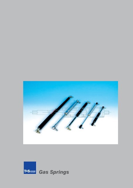
T & STECHNIKSYSTEMGas SpringsT&S <strong>Systemtechnik</strong> GmbH Am Hintergraben 26 D- 64319 Pfungstadt Telefon +49 6157-8087-0 Fax +49 6157-8087-188 sales@ts-systemtechnik.de
T & STECHNIKSYSTEMIndexPageIntroductionImportant Information 1Calculations and Mounting Guide 2Gas Spring Sizing Information 3Frequently Asked Questions 4Gas SpringsOverview 6Swift & Sure 7Stop & Stay 8Econoloc 9Stainless Steel 10AccessoriesVari-Lift 11Dampers 12End Fittings 13Mounting Brackets 18Blocklift 22Application Enquiry Form 24T&S <strong>Systemtechnik</strong> GmbH Am Hintergraben 26 D- 64319 Pfungstadt Telefon +49 6157-8087-0 Fax +49 6157-8087-188 sales@ts-systemtechnik.de
T & STECHNIKSYSTEMImportant informationT&S <strong>Systemtechnik</strong> - Your Partner for fully developed technical solutionsThe customer focus is one of the most important elements of our company. We see ourselves mainly as a providerof system solutions. Together with our design engineers and the latest manufacturing techniques we are able, tocreate custom solutions for individual applications.We would appreciate it, if we could start a good and successful business relationship and solve together all yourindividual and technical challenges.Important Gas Spring InformationWe have built up an enviable reputation for customer service, recognising that no two applications are the same.For this reason our Gas Springs are made to order to suit the individual requirements of each application, thismeans that you get the perfect gas spring for your application.Furthermore, some applications require special solutions concerning flexibility, safety and finish.Because of these reasons it is unfavourable to offer single product numbers, price lists or fixed product ranges.We create for every request an appropriate offer wich is perfectly fitted for your requirements.Please fill in our Application Enquiry Form on page 24. We will then be able to create an adequate offer.Compression lengthExtended lengthStroke Tube lengthTubeConnector tubePiston rodConnector piston rodT&S <strong>Systemtechnik</strong> GmbH Am Hintergraben 26 D- 64319 Pfungstadt Telefon +49 6157-8087-0 Fax +49 6157-8087-188 sales@ts-systemtechnik.de1
T & STECHNIKSYSTEMCalculations and Mounting GuideIf desired, we determine the optimal values for your application.Below is a basic calculation which gives an approximation of the minimum required gas spring force for a specifiedmounting position geometry.Please remember, we offer an Engineering application solutions service. Through the use of our expert systemselection software we can quickly determine the optimum mounting points, the resultant handling forces (bothopening and closing forces) and recommend the correct gas spring specification and part number.Estimating Gas Spring Force F1 (N)F1 = G x XGLS x AZ = Length of lid from pivot (hinge) point in mmXG = Centre of Gravity (mm). (N.b. take accountof Uneven distribution of weight, dependingon lid Shape, handles, locks andother components)G = Weight of lid in Newtons (kg x 10)LS = Radius of Gas Spring Force (mm)A = Number of gas springs per application, 2 isusually recommended.Worked Example for EstimatingGas Spring Force F1 (N)200N x 450mmF1 =245mm x 2F1 = 183,67NTo estimate the closing effort F2 (N)F2 =F2 =A x F1 x LSZ2 x 183,67 x 245900F2 = 100N2T&S <strong>Systemtechnik</strong> GmbH Am Hintergraben 26 D- 64319 Pfungstadt Telefon +49 6157-8087-0 Fax +49 6157-8087-188 sales@ts-systemtechnik.de
T & STECHNIKSYSTEMGas Spring Sizing InformationMatching different suppliers gas springs:If you have an existing gas spring, you will require the following dimensions to simplify the selection ofan equivalent gas spring:• The rod and tube diameters• The stroke length (from the shoulder of thread or end connector to the tube)• The extended length from the centre of the end connectors, or stud end shouldersif no end connectors are used• The type of end connectors used• The nominal force of the gas springThe first Dimension to take is the Rod/Tube Diameter, this signifies which size springyou need to look at i.e. size 6-15, 8-18, 10-23 and 14-28.Then you need to first carify the extended length of the gas spring. (Depending on theapplication this is important). Secondly, you need to clarify the closed length if possibleto check/match to the closest available stroke lengthThe approximate weight of the lid to be lifted in kg‘s. (See table below). This helps toconfirm that you are using an appropriate size gas spring.Gas SpringSizeApproximateLid Weight (kg)Force Rangein Newton‘s6/15 to 10 50 - 4008/18 10 - 40 100 - 65010/23 40 - 150 150 - 120014/28 150 - 350 200 - 2500Notes:Gas Springs are charged with nitrogen at very high pressures and under no circumstances should they be openedor subjected to excessive loads.Gas Springs must not be exposed to bending forces, tensile forces or side loads. Where possible we recommendthe use of ball joints as this will assist in reducing the impact of any misalignment. If you have to use eye connectorsremember to support the eye on both sides and allow some float.Where possible protect the piston rod from impact, damages, scratches, dirt or contamination such as paint oradhesives. Protective plain shrouds are available . Please contact us for further details.T&S <strong>Systemtechnik</strong> GmbH Am Hintergraben 26 D- 64319 Pfungstadt Telefon +49 6157-8087-0 Fax +49 6157-8087-188 sales@ts-systemtechnik.de3
T & STECHNIKSYSTEMFrequently Asked QuestionsShould a Gas Spring be mounted “Rod up” oder “Rod down”“Rod down” is the preferred orientation for mounting a Gas Spring.An optimum design would permit the support to be oriented rod down trough its entire actuation. There are severalreasons for this: In order to achieve the damping “cushion” at the end of the Gas Spring’s stroke, the piston assemblyinside of the Gas Spring must travel through oil at the end of the stroke. “Rod down” orientation ensures that theoil is in the proper location for full damping occur. “Rod down” orientation ensures that the rod and sealing componentsare lubricated with every stroke of the Gas spring. This reduces seal wear and helps to inhibit corrosion.What type of end connectors can be used when mounting a Gas Spring or Damper?When choosing an end connector, the designer must take into account both tensile and compressive loading toensure adequate strength and wear. We provide a wide range of end connectors including nylon, zinc, steel andstainless steel.The most common connector involves a ball and socket joint. While this joint is available in many forms, they allallow rotation about the mounting point, which helps to reduce/minimise side loading on the Gas Spring or Damper.This is important because side loading can reduce the life of the product. Side load may be caused by slightmisalignment or twisting in the application.The design engineer should also be concerned with the clearance around the mounting point. There should beenough room to easily mount and remove the unit from the application.How does the temperature affect the life and performance of a Gas Spring or Damper?As the temperature of the Gas Spring changes, the internal pressure changes according to the relationshipP1/T1 = P2/T2. Therefore, as the temperature increases, so does the internal pressure. As the internalpressure increases, so does the output force. For every 10°C (18°F) change in temperature, the output forcechanges 3,5 percent.Very high or very low temperatures can adversely affect the Gas Spring’s ability to retain its gas charge. At veryhigh temperatures, the permeability of rubber increases and the gas molecules may diffuse through the seal morequickly. Additionally, rubber compounds may begin to soften at elevated temperatures and lose their ability to sealproperly. At very low temperatures, rubber compunds may stiffen and also lose their ability to seal properly. Ourseal design and rubber compound helps to minimize problems at temperatures extremes. This allows to performreliably at temperatures ranging from -40°C (-40°F) to 80°C (176°F).What is the expected life of a Gas Spring?When estimating the life of a Gas Spring, one must first determine how much force the support can lose before theapplication becomes unacceptable. The time it takes to lose this amount of force is considered to be the life of thesupport.All Gas Springs lose output force over time. The rate at which force loss occurs varies greatly between applicationand manufacturer. Many factors affect the rate of force loss, such as: size of the support, orientation, amount ofcycles, ambient temperature, vibration and the geometry of the application and time (cycle time). Considering all ofthe variables, it is very difficult to estimate life accurately without actual testing on the application.It is recommended that the Gas Springs be periodically checked to ensure that they are functioning as intended.This inspection should be implemented as part of a planned maintenance activity, if possible.4T&S <strong>Systemtechnik</strong> GmbH Am Hintergraben 26 D- 64319 Pfungstadt Telefon +49 6157-8087-0 Fax +49 6157-8087-188 sales@ts-systemtechnik.de
T & STECHNIKSYSTEMFrequently Asked QuestionsHow can a designer ensure the longest life for a Gas spring in application?Orient the support “Rod down”. As explained above, this will continually lubricate the seal and rod and reducepermeation through the seal.Utilize the largest gas volume possible in the support. In general use the minimum stroke required with the largestbody possible. In a support with a large gas volume, small gas losses are imperceptible in the output force.The temperature of the Gas Spring should remain well within the temperature limits.If temperatures extremes will be encountered, it should be for a short duration and the support should not be cycledwhile at the extremes.Utilize the highest force Gas Spring possible that still provides acceptable handling loads for the application.This will allow for some force loss without the loss of function of the application. Avoid side load, vibration,contamination, and damage to the rod.Provide multiple mounting locations so that the support can be moved to accommodate for force loss as thesupport ages.For further information or quiestions please feel free to contact us. We will be glad to help you.T&S <strong>Systemtechnik</strong> GmbH Am Hintergraben 26 D- 64319 Pfungstadt Telefon +49 6157-8087-0 Fax +49 6157-8087-188 sales@ts-systemtechnik.de5
T & STECHNIKSYSTEMGas Spring SolutionsEconomic solutions for various standardsWith the realisation that no application equals another, we provide technically fully developed products wich fulfillyour individual requirements. Together, we can select the most appropriate Gas Spring for your application and weprovide Fixed Force or Vari-Lift prototypes quickly for testing on your application.The following pages provide a detailled overview about our favourable Gas Springs for various standards.These products provide quality engineered solutions that you can rely on, time and time again.SWIFT & SURESwift & Sure is one of the mostpopular gas spring and is availablein an extensive range ofsizes for a wide variety of applications.STAINLESS STEELOur stainless steel gas springsand end fittings are available inan extensive range of sizes. Thisrange gives increased corrosionresistance in harsh and cleanenvironments.ECONOLOCEconoloc gas springs eliminatethe need for separate safetyrods in critical lift-assist applications.They positively lock whenfully extended, protecting theoperator from potential injury inthe event of overload or misuse.STOP & STAYStop & Stay gas springs enablemulti-position holding of a counterbalanced weight over the entirestroke of the gas spring.VARI-LIFTVari-Lift is an adjustable forcegas spring that can be adjustedto meet individual preferences.It can also be adjusted whilst inposition, saving you both timeand effort.DAMPERSDampers are specifically designedto influence the characteristicsof movement. They providea controlled arrest of a weightor lid across a variety of industrialapplications. Typical motioncontrol uses for dampers include;velocity control, decelerationcontrol and momentum change.BLOCKLIFTBlocklift gas springs can bestopped at any position duringoperation. They are fitted with aspecial locking valve that will onlyallow the spring to be movedwhen a release pin is pressed.Apart from these series we also offer special designs, Dampers, Shield Tubes and 8/19 Gas Springs.Feel free to contact us!6T&S <strong>Systemtechnik</strong> GmbH Am Hintergraben 26 D- 64319 Pfungstadt Telefon +49 6157-8087-0 Fax +49 6157-8087-188 sales@ts-systemtechnik.de
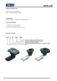
SWIFT & SUREFor most frequent applicationsT & STECHNIKSYSTEMProduct description / technical dataSWIFT & SURE is available in an extensive range of sizes and witha wide range of end connectors and brackets for a wide variety ofapplicationsA Gas Spring is an entirely self-contained, maintenance free, hydropneumaticram which is charged under pressure with an inert gas (Nitrogen).It has the characteristics of a compression spring which, coupled witha small change in force as it extends, provides a controlled rate ofmovement. At the end of the extension stroke, oil damping occurs dueto a hydraulically cushioned zone. These features help protect hingesand mounts by applying constant force with a damped end of travel.SWIFT & SURE GAS SPRINGS are ideally suited for use on vehicles of anysize, machine guards, lockers, access panels, hood supports, hatchcovers, lids and much more.Benefits:• Self Contained unit and maintenance free• Safe to use with easy finger-tip control• Custom design, sized to your application• Custom force or adjust yourself option• Over 2,500 different combinations• DIN ISO 9001 Registered CompanyDiameterPiston Rod/CylinderStroke length(In 5 mmincrements)Tube length(In 1 mmincrements)Force range(In 10 Nincrements)Thread type6 mm / 15 mm 40 - 200 75 - 235 50 - 400 M5 x 0.88 mm / 18 mm 40 - 300 85 - 345 100 - 650 M6 x 1.010 mm / 23 mm 40 - 400 85 - 445 150 - 1200 M8 x 1.2514 mm / 28 mm 40 - 500 95 - 555 200 - 2500 M10 x 1.5Different Gas Spring sizes available.Thread type (M)STROKE LENGTH (+/- 1 mm)TUBE LENGTH (+/- 1 mm)EXTENDED LENGTH (+/- 2mm)T&S <strong>Systemtechnik</strong> GmbH Am Hintergraben 26 D- 64319 Pfungstadt Telefon +49 6157-8087-0 Fax +49 6157-8087-188 sales@ts-systemtechnik.de7
STOP & STAYMulti-position holdingT & STECHNIKSYSTEMProduct description / technical dataSTOP & STAY gas springs enable multi-position holding of acounter balanced weight over the entire stroke of thegas spring.Stop & Stay Gas Springs are easy to fit with simple adjustment todetermine the correct level of support. Once fitted, finger tip controlallows movement to any position required. The lock-nut is adjusted tosuit the application‘s weight (about a half turn), thereby applyinga ‘stick-slip’ friction to the rod.STOP & STAY gas springs are ideal for a wide variety of applicationssuch as printer canopies, monitor arms, acoustic hoods, delicatessencounters, sunbeds and many more.Typically, the gas spring force is pre-set to carry the weight of theapplication (e.g. a canopy) in the normal manner. This allows the userto raise, lower and position the canopy in any position using theminimum of effort and in quick time.Benefits• Multi-position holding of counter-balanced weights• Simple adjustment to determine correct setting• Positional control• Safe to use and operate• Maintenance free• DIN ISO 9001 Registered CompanyDiameterPiston Rod/CylinderStroke length(In 5 mmincrements)Tube length(In 1 mmincrements)Force range(In 10 Nincrements)Thread type6 mm / 15 mm 40 - 200 75 - 235 50 - 400 M5 x 0.88 mm / 18 mm 40 - 300 75 - 335 100 - 650 M6 x 1.010 mm / 23 mm 40 - 400 80 - 440 150 - 1200 M8 x 1.25Different Gas Spring sizes available.Thread type (M)SETTING (10 - 15 mm)STROKE LENGTH (+/- 1 mm)TUBE LENGTH (+/- 1 mm)EXTENDED LENGTH (+/- 2mm)*Breite hängt von der Größe der Gasdruckfeder ab8T&S <strong>Systemtechnik</strong> GmbH Am Hintergraben 26 D- 64319 Pfungstadt Telefon +49 6157-8087-0 Fax +49 6157-8087-188 sales@ts-systemtechnik.de
ECONOLOCProtection through locking deviceT & STECHNIKSYSTEMProduct description / technical dataECONOLOC Gas Springs eliminate the need for separate safetyrods in critical lift-assist applications.They positively lock when fully extended, protecting the operator frompotential injury in the event of overload or misuse.Simple to use, the lockable Gas Spring operates automatically. Whenthe Gas Spring is fully extended a spring loaded locking shroudmoves into place, preventing the Gas Spring from compressing.The Econoloc is manually released by applying thumb pressure tothe designated area of the locking shroud, allowing the gas spring tocompress in a controlled manner.THE ECONOLOC range of gas springs combine superior quality withthe added safety feature required in many heavy duty applications,such as trucks, construction machinery, switch gear and agriculturalequipment. A single ECONOLOC gas spring can be used inconjunction with a standard SWIFT & SURE version.Leistungsmerkmale:• Eliminates the need for separate safety rodsin critical lift-assist operations• Operates automatically• Safe & easy to use• Self-contained and maintenance free unit• DIN ISO 9001 Registered CompanyDiameterPiston Rod/CylinderStroke length(In 5 mmincrements)Tube length(In 1 mmincrements)Force range(In 10 Nincrements)Thread type8 mm / 18 mm 40 - 300 85 - 345 100 - 650 M6 x 1.010 mm / 23 mm 40 - 400 85 - 445 150 - 1200 M8 x 1.2514 mm / 28 mm 40 - 500 95 - 555 200 - 2500 M10 x 1.5Different Gas Spring sizes available.Thread type (M)HubSTROKE LENGTH (+/- 1 mm)TUBE LENGTH (+/- 1 mm)EXTENDED LENGTH (+/- 2mm)T&S <strong>Systemtechnik</strong> GmbH Am Hintergraben 26 D- 64319 Pfungstadt Telefon +49 6157-8087-0 Fax +49 6157-8087-188 sales@ts-systemtechnik.de9
STAINLESS STEELHigh corrosion resistanceT & STECHNIKSYSTEMProduct description / technical dataSTAINLESS STEEL Gas Springs are based on SWIFT & SURE series.Manufactured in 1.4404 stainless steel, this range of Gas Spring givesincreased corrosion resistance in industrial, marine and costal environments.With a specially prepared rod surface finish for additionalhardness and protection against high levels of corrosion, STAINLESS STEELSwift & Sure gas springs are ideally suited for use in harsh environmentapplications such as marine engine covers, doors and applicationenvironments requiring high levels of cleanliness like the food,pharmaceutical and medical industries.STAINLESS STEEL Swift & Sure gas springs are available in an extensiverange of sizes.Benefits:• High corrosion resistance for external applications• 1.4404 stainless steel tube & rod• Hygienic and non-magnetic• Custom design sized to your application• Self-contained and maintenance free unit• DIN ISO 9001 Registered CompanyDiameterPiston Rod/CylinderStroke length(In 5 mmincrements)Tube length(In 1 mmincrements)Force range(In 10 Nincrements)Thread type6 mm / 15 mm 40 - 200 70 - 230 50 - 400 M5 x 0.88 mm / 18 mm 40 - 300 85 - 345 100 - 650 M6 x 1.010 mm / 23 mm 40 - 400 85 - 445 150 - 1200 M8 x 1.25Different Gas Spring sizes available.Thread type (M)STROKE LENGTH (+/- 1 mm)TUBE LENGTH (+/- 1 mm)EXTENDED LENGTH (+/- 2mm)10T&S <strong>Systemtechnik</strong> GmbH Am Hintergraben 26 D- 64319 Pfungstadt Telefon +49 6157-8087-0 Fax +49 6157-8087-188 sales@ts-systemtechnik.de
VARI-LIFTOptimal force adjustmentT & STECHNIKSYSTEMProduct description / technical dataVARI-LIFT is an adjustable force Gas Spring that can be set to meetindividual preferences. It can also be adjusted whilst in positionon the application, saving you both time and effort.When Gas Springs are used, it is often found that theoretical forceswill be incorrect because factors such as hinge friction and perceivedspeed of action will have a bearing on calculations.The Gas Springs are charged to their maximum force during manufacture.By using the standard tool provided, gas can be graduallyreleased via the VARI-LIFT valve at the end of the tube to provide theforce suited to your application. Once this has been established, weare able to measure this force and provide production fixed force GasSprings to your precise requirement.VARI-LIFT Gas Springs can also be used if panel weights vary. Thespring force ranges from 50 Newton (5 kg or 11Ibs) to 2500 Newton(250 kg or 550 Ibs) with standard strokes from 40 mm (1.57“) to 500mm (19.69“).Benefits:• No need to calculate force• Adjustable to any force within range• Force can be adjusted after installation• Ideal for prototyping and short production runs• Available as an option on most types of our Gas SpringsVari-Lift versions of the following Gas Spring ranges are available:SWIFT & SUREFor most frequent applicationsSTOP & STAYMulti-position holdingECONOLOCProtection through locking deviceSTAINLESS STEELHigh corrosion resistanceThread type (M)Vari-Lift valveSTROKE LENGTH (+/- 1 mm)TUBE LENGTH (+/- 1 mm)EXTENDED LENGTH (+/- 2mm)T&S <strong>Systemtechnik</strong> GmbH Am Hintergraben 26 D- 64319 Pfungstadt Telefon +49 6157-8087-0 Fax +49 6157-8087-188 sales@ts-systemtechnik.de11
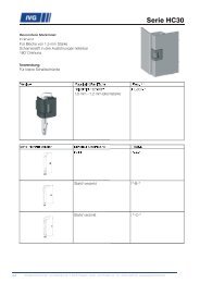
DampersT & STECHNIKSYSTEMProduct description / technical dataDAMPERS are designed to influence the characteristics of movement.Our DAMPERS are self contained oil filled rod and tube assemblies withoutgas. The hydraulic damping unit comprises of a tube, rod andpiston system with the movement of the piston through the oil creatingthe damping charateristics.Generally, DAMPERS are specifically designed to influence the characteristicsof movement by providing the controlled arrest of a weight or lidacross a variety of industrial applications. Typical motion control usesfor dampers include; velocity control, deceleration control and momentumchange.DAMPERS provide damping either in extension, compression or both directions.Benefits:• Custom design, sized to your application• Self contained unit and maintenance free• Compact design with high durability and reliability• Operating temperature range from -40OC to +100OC• BS EN ISO 9001 Registered CompanyDiameterPiston Rod/CylinderStroke length(In 5 mm increments)Tube length(In 1 mm increments)Force range(In 10 N increments)8-18 40-300 85-345 M6 x 1.012T&S <strong>Systemtechnik</strong> GmbH Am Hintergraben 26 D- 64319 Pfungstadt Telefon +49 6157-8087-0 Fax +49 6157-8087-188 sales@ts-systemtechnik.de
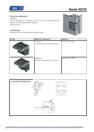
End FittingsFlexibility through varietyT & STECHNIKSYSTEMProduktbeschreibung / Technische AngabenEND FITTINGS match perfectly to our Gas Springs and allow aflexible and easy mounting.Our Gas Springs offer a wide range of end fittings to suit yourapplication, manufactured from a range of finishes and materialsincluding nylon, steel and zinc. End fittings can be either the same oneach end, or have different sizes and types to suit your requirements.If you have any questions about specifying your Gas Spring, we will bepleased to help you.Benefits:• Many different designs and sizes for flexibility of mounting• Range of materials and finishesl• Designed to suit your application• Maintenance free• DIN ISO 9001 Registered CompanyWe offer a wide range of forms and sizes - here a short excerpt:Steel Ball Joint Nylon Ball Joint Flat Eye Clevis Fork Nylon EyeFor a detailled measurement please order our specifications sheet.T&S <strong>Systemtechnik</strong> GmbH Am Hintergraben 26 D- 64319 Pfungstadt Telefon +49 6157-8087-0 Fax +49 6157-8087-188 sales@ts-systemtechnik.de13
End FittingsFlexibility through varietyT & STECHNIKSYSTEMProduct description / technical dataNylon Ball JointsJ(+/-)K(+/-)P1 P2 P5 P7 P8 PA9.0 mm0.5 mm10.3 mm0.25 mm14.0 mm0.5 mm9.0 mm0.2 mm12.0 mm0.5 mm12.5 mm0.25 mmNOPINNOPING M5 x 0.8 M5 x 0.8 M8 x 1.25 NOPINNOPINNOPINNOPIN14.0 mm0.5 mm9.0 mm0.2 mmM5 x 0.8C M5 x 0.8 M5 x 0.8 M6 x 1.0 M5 x 0.8 M6 x 1.0 M6 x 1.0L(+/-)17.5 mm0.5 mm17.5 mm0.5 mm17.5 mm0.5 mm17.5 mm0.5 mm17.5 mm0.5 mm17.5 mm0.5 mmNylon EyesE(+/-)M(+/-)L(+/-)E1 E2 E3 E4 E56.1 mm0.08 mm8.1 mm0.05 mm17.0 mm0.5 mm7.35 mm0.05 mm7.0 mm0.2 mm17.0 mm0.5 mm8.1 mm0.05 mm10.0 mm0.12 mm21.0 mm0.25 mm6.1 mm0.05 mm10.0 mm0.12 mm21.0 mm0.25 mm10.1 mm0.05 mm10.0 mm0.12 mm21.0 mm0.25 mmC M5 x 0.8 M5 x 0.8 M6 x 1.0 M6 x 1.0 M6 x 1.0Flat Steel EyesE(+/-)M(+/-)L(+/-)F1 F2 F3 F4 FD6.1 mm0.12 mm3.0 mm0.12 mm22.0 mm0.25 mm8.1 mm0.12 mm5.0 mm0.12 mm25.0 mm0.25 mm10.2 mm0.12 mm5.0 mm0.12 mm25.0 mm0.25 mm8.2 mm0.12 mm8.0 mm0.12 mm32.0 mm0.25 mm10.0 mm0.12 mm10.0 mm0.12 mm32.0 mm0.25 mmC M5 x 0.8 M6 x 1.0 M6 x 1.0 M8 x 1.25 M10 x 1.514T&S <strong>Systemtechnik</strong> GmbH Am Hintergraben 26 D- 64319 Pfungstadt Telefon +49 6157-8087-0 Fax +49 6157-8087-188 sales@ts-systemtechnik.de
End FittingsFlexibility through varietyT & STECHNIKSYSTEMProduct description / technical dataSteel Clevis ForksE(+/-)M(+/-)L(+/-)C1 C2 C3 C45.0 mm0.25 mm5.14 mm0.12 mm20.0 mm0.5 mm6.0 mm0.25 mm6.15 mm0.12 mm24.0 mm0.5 mm8.0 mm0.25 mm8.15 mm0.12 mm32.0 mm0.5 mm10.0 mm0.25 mm10.15 mm0.12 mm37.0 mm0.5 mmC M5 x 0.8 M6 x 1.0 M8 x 1.25 M10 x 1.5Steel Ball Jointsmm‘sJ(+/-)K(+/-)GL(+/-)CB1 B2 B3 B4 B5 B6 B8 B912.00.59.00.3M5 x0.818.00.25M6 x1.012.00.512.50.5M8 x1.2518.00.25M6 x1.012.00.512.50.55/16“UNC18.00.25M6 x1.013.00.216.50.5M8 x1.2530.00.25M8 x1.2513.00.216.50.55/16“UNC30.00.25M8 x1.2516.00.2520.00.5M10 x1.535.00.3M10 x1.5NOPINNOPINNOPIN18.00.25M6 x1.0NOPINNOPINNOPIN30.00.25M8 x1.25Zinc EyesZ2 Z3 Z4 Z5E(+/-)M(+/-)L(+/-)8.3 mm0.1 mm10.0 mm0.12 mm21.0 mm0.25 mm10.3 mm0.1 mm10.0 mm0.12 mm21.0 mm0.25 mm8.3 mm0.1 mm10.0 mm0.12 mm21.0 mm0.25 mm10.3 mm0.1 mm10.0 mm0.12 mm21.0 mm0.25 mmC M6 x 1.0 M6 x 1.0 M8 x 1.25 M8 x 1.25S1 S4 S6 S8M M8 x 1.25 M10 x 1.5 M5 x 0.8 M6 x 1.0L 12 mm 12 mm 10 mm 10 mmStandardø10 - 23 14 - 28 6 - 15 8 - 18T&S <strong>Systemtechnik</strong> GmbH Am Hintergraben 26 D- 64319 Pfungstadt Telefon +49 6157-8087-0 Fax +49 6157-8087-188 sales@ts-systemtechnik.de15
Stainless Steel End FittingsFlexibility through varietyT & STECHNIKSYSTEMProduct description / technical dataStainless Steel Ball JointsG1(B2 equivalent)G5(B4 equivalent)J(+/-)K(+/-)12.0 mm0.3 mm12.5 mm0.3 mm13.00 mm0.3 mm16.5 mm0.3 mmG M8 x 1.25 M8 x 1.25L(+/-)18.0 mm0.3 mm30.0 mm0.3 mmC M6 x 1.0 M8 x 1.25All Nylon Ball Joints - Stainless Steel PinsJ(+/-)K(+/-)PE PV PW9.0 mm0.25 mm10.3 mm0.25 mm12.0 mm0.25 mm12.5 mm0.5 mmNOPIN*NOPIN*G M5 x 0.8 M8 x 1.25 NOPIN*C M5 x 0.8 M6 x 1.0 M6 x 1.0L(+/-)17.5 mm0.5 mm18.0 mm0.25 mm18.0 mm0.25 mm16T&S <strong>Systemtechnik</strong> GmbH Am Hintergraben 26 D- 64319 Pfungstadt Telefon +49 6157-8087-0 Fax +49 6157-8087-188 sales@ts-systemtechnik.de
Stainless Steel End FittingsFlexibility through varietyT & STECHNIKSYSTEMProduct description / technical dataNylon EyesE1 E2 E3 E4 E5E(+/-)M(+/-)L(+/-)6.1 mm0.08 mm8.1 mm0.05 mm17.0 mm0.5 mm7.35 mm0.05 mm7.0 mm0.2 mm17.0 mm0.5 mm8.1 mm0.05 mm10.0 mm0.12 mm21.0 mm0.25 mm6.1 mm0.05 mm10.0 mm0.12 mm21.0 mm0.25 mm10.1 mm0.05 mm10.0 mm0.12 mm21.0 mm0.25 mmC M5 x 0.8 M5 x 0.8 M6 x 1.0 M6 x 1.0 M6 x 1.0Stainless Steel Flat EyesJ1J2E(+/-)M(+/-)L(+/-)8.0 mm0.036 mm/-0.005.12 mm0.12 mm25.0 mm0.25 mm8.0 mm0.036/-0.008.12 mm0.12 mm32.0 mm0.25 mmC M6 x 1.0 M8 x 1.25Stainless Steel Clevis ForksH1H2E(+/-)M(+/-)L(+/-)6.0 mm0.036/-0.006.25 mm+/-0.10 mm24.0 mm0.25 mm8.0 mm0.036/-0.008.27 mm0.12 mm32.0 mm0.25 mmC M6 x 1.0 M8 x 1.25T&S <strong>Systemtechnik</strong> GmbH Am Hintergraben 26 D- 64319 Pfungstadt Telefon +49 6157-8087-0 Fax +49 6157-8087-188 sales@ts-systemtechnik.de17
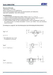
Mounting BracketsSolid connectionT & STECHNIKSYSTEMProduct description / technical dataThe new brackets are designed to suit the extensive range of ourend fittings, creating a wide range of easy-to-assemble fixingoptions.This flexibility makes our products more attractive than ever, combinedwith our unique VARI-LIFT technology, which allows design engineers tovary the gas spring pressure during prototyping.Available in a wide range of styles, including 90 degree, flat and raised,the new brackets are drilled to accept M4 and M6 fixings - making iteasier to fasten to timber and steel frameworks using screws or dowels.They are designed to accept DIN/ISO standard fixings.Manufactured in carbon steel with zinc and yellow passivate, the componentshave passed a minimum of 72 hours of salt spray testing.Benefits:• Wide range of mounting types• High corrosion resistance• Drilled to accept M4 and M6 fixings• Designed to accept DIN/ISO standart fixings• DIN ISO 9001 Registered CompanyWe offer a wide range of forms and sizes - here a short excerpt:Raised Bracket with Pin Raised Bracket with Ball Flat Bracket withThreaded PinFlat Bracket withBall PinFlat Bracket withPlain Hole90º Bracket with Threaded Pin 90º Bracket with Ball Pin 90º Bracket withPlain HoleFor a detailled measurement please order our specifications sheet.18T&S <strong>Systemtechnik</strong> GmbH Am Hintergraben 26 D- 64319 Pfungstadt Telefon +49 6157-8087-0 Fax +49 6157-8087-188 sales@ts-systemtechnik.de
Mounting BracketsSolid connectionT & STECHNIKSYSTEMProduct description / technical dataRaised Bracket with PinStyle Code A B C D E F G H I J K L M N O P Q R RecommendedEnd FittingRaisedPinKPR 55 2 44 33 3 30 4.3 41 6.5 8 - - - - - 2.5 M8 x1.25Dimensions in mm16 E3 F2 Z2 Z4erhöht mit GewindebolzenRaised Bracket with BallStyle Code A B C D E F G H I J K L M N O P Q R RecommendedEnd FittingRaised KBR 55 2 44 - 10 30 4.3 41 6.5 8 - - - - 12 - - - B8 P8 P9BallDimensions in mmerhöht mit KugelbolzenFlat Bracket with Threaded PinStyle Code A B C D E F G H I J K L M N O P Q R RecommendedEnd FittingFlat KPF 70 3 48 30 3 55 4.3 25 6.5 8 - - - - 25 2.5 M8 xDimensions in mm1.2516 E3 F2 Z2 Z4flach mit GewindebolzenT&S <strong>Systemtechnik</strong> GmbH Am Hintergraben 26 D- 64319 Pfungstadt Telefon +49 6157-8087-0 Fax +49 6157-8087-188 sales@ts-systemtechnik.de19
Mounting BracketsSolid connectionT & STECHNIKSYSTEMProduct description / technical data90º Bracket with Threaded PinStyle Code A B C D E F G H I J K L M N O P Q R RecommendedEnd FittingFlat KPR 70 3 - - 3 55 4.3 25 6.5 - 25 30 18 20 25 2.5 M8 x1.25Dimensions in mm16 E3 F2 Z2 Z490° Winkel mit GewindebolzenFlat Bracket with Ball PinStyle Code A B C D E F G H I J K L M N O P Q R RecommendedEnd FittingFlat KBF 70 3 48 30 10 55 4.3 25 6.5 8 - - - - 12 - - - B8 P8 P9Dimensions in mmflach mit Kugelbolzen90º Bracket with Ball PinStyle Code A B C D E F G H I J K L M N O P Q R RecommendedEnd Fitting90DegKBN 70 3 - - 10 55 4.3 25 6.5 - 25 30 18 20 12 - - - B8 P8 P9Dimensions in mm90° Winkel mit Kugelbolzen20T&S <strong>Systemtechnik</strong> GmbH Am Hintergraben 26 D- 64319 Pfungstadt Telefon +49 6157-8087-0 Fax +49 6157-8087-188 sales@ts-systemtechnik.de
Mounting BracketsSolid connectionT & STECHNIKSYSTEMProduct description / technical dataFlat Bracket with Plain HoleStyle Code A B C D E F G H I J K L M N O P Q R RecommendedEnd FittingFlat KHF 70 3 48 30 8.5 55 4.3 25 6.5 8 - - - - - - - - B2 BN P5Dimensions in mmflach mit Bohrung90º Bracket with Plain HoleStyle Code A B C D E F G H I J K L M N O P Q R RecommendedEnd Fitting90DegDimensions in mmKHN 70 3 - - 8.5 55 4.3 25 6.5 - 25 30 18 20 - - - - B2 BN P590° Winkel mit BohrungT&S <strong>Systemtechnik</strong> GmbH Am Hintergraben 26 D- 64319 Pfungstadt Telefon +49 6157-8087-0 Fax +49 6157-8087-188 sales@ts-systemtechnik.de21
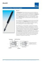
BlockliftT & STECHNIKSYSTEMProduct description / technical dataBLOCKLIFTBLOCKLIFT gas springs can be stopped at any position during operation.They are fitted with a special locking valve that will only allow the springto be moved when a release pin is pressed.Blocklifts are excellent way of moving an application to any position atthe discretion of the operator, the blocklifts will also allow a load to beapplied to the application while it is locked in any of the infinite lockedpositions.Our range of BLOCKLIFT gas springs work like conventional gas springswith the addition of an internal locking mechanism that can be stoppedimmediately in any position. This locking mechanism only allows thespring to move while the release pin, located on either the end of thepiston rod or tube end, is activated.Adjustable Blocklifts are commonly used for; back rest adjustment ofpassenger seats on buses, trains and office chairs, adjusting hospitalbeds, massage tables and wheelchairs and height adjustment ontables, desktops and school desks.PistonNozzleThe arrow shows theTransfer of relevant Medium(oil or gas) throughthe valveValve in closed position Valve in opened positionRelease LeverTube22T&S <strong>Systemtechnik</strong> GmbH Am Hintergraben 26 D- 64319 Pfungstadt Telefon +49 6157-8087-0 Fax +49 6157-8087-188 sales@ts-systemtechnik.de
BlockliftT & STECHNIKSYSTEMProduct description / technical dataBLOCKLIFT size availabilitySize Availability (mm)Type Description 8-22 8-28 10-22 10-24 10-28 10-40 14-40BL1 Rigid in extensionBL2 Rigid in compressionBL3 Spring blockingBL4 Rigid in extension & compressionBL5 M-BlockliftBL6 Rigid in extension - Not lockable in compressionBL7 Rigid in compression - Not lockable in extensionBL8 Gas Traction BlockliftBLT2 Rigid in compressionBLT3 Spring BlockingBlT4 Rigid in compressionBL1 – RIGID IN EXTENSIONThis gas spring locks the pistonin extension giving totalrigidity, but will permit a fewmillimetres of movement incompression. Once the loadis released, the piston rod automaticallyreturns to the initialposition. These springs canbe mounted in any position.BL2 – RIGID IN COMPRESSIONThis gas spring provides totalrigidness in compression, butwill permit a few millimetres ofmovement in extension. Oncethe load is released, the pistonrod automatically returns to theinitial position. These springscan be mounted in anyposition.BL3 – SPRING BLOCKINGThis gas spring is ideal for applications wheresome comfort (cushioning or elasticity) is neededeven when the Blocklift is locked. The BL3can also be modified to be rigid in extension,providing a shorter stroke than a standardBL1; or rigid in compression, providing a shorterstroke than a standard BL2.BL4 – RIGID IN EXTENSION &COMPRESSIONThe BL4 is totally rigid in bothextension and compression.It is available with or withoutan extension force, dependingon whether you needthe gas spring to control theapplication or if the applicationis controlled by an externalmechanism.BL5 – M-BLOCKLIFTThe BL5 is a compact andresponsive gas spring with afast extension speed and isideal for height adjustmentapplications, such as tablesand desks, etc. as it providesrelative rigidity in compressionand can be mountedeither rod up or down.BL6 – RIGID IN EXTENSION- NOT LOCKABLE IN COMPRESSIONThe BL6 gas spring is lockable and rigid inextension but is not lockable in compression. Thisgas spring is ideal if you need to control an applicationin extension (push out). The gas spring will freelycompress (push in) when an external load is appliedbut will only extend when the release pin is activated.BL7 – RIGID IN COMPRESSION– NOT LOCKABLE IN EXTENSIONThe BL7 works in the oppositewayto the BL6. This gasspring is lockable in compression(push in) by tivating therelease pin but works freely inextension when the appliedexternal load is removed.BL8 – GAS TRACTION BLOCKLIFTThe principle of the BL8 is theopposite of standard gassprings. While a standard gasspring is always extending, heBL8 is designed to close andcan be locked in any position.T-BLOCKLIFTThe release pin on standard Blocklift gas springsis located on the piston rod. T-Blocklift gas springshave the release pin located on the tube end.This design allows shorter extended lengthscompared to standard Blocklifts and is availablerigid in compression and spring blocking.T&S <strong>Systemtechnik</strong> GmbH Am Hintergraben 26 D- 64319 Pfungstadt Telefon +49 6157-8087-0 Fax +49 6157-8087-188 sales@ts-systemtechnik.de23
Gas Spring Application Enquiry Form
T & STECHNIKSYSTEMPlease ask for catalogues for other product lines:- Equipment Levelling Feet- Quarter Turn Fasteners- Refrigeration Components- Tension Latches- Gas Springs- Threaded Inserts- CamlocksT&S <strong>Systemtechnik</strong> GmbHAm Hintergraben 26D-64319 PfungstadtTelefon: +49 (0)6157-8087-0Fax: +49 (0)6157-8087-188E-Mail: sales@ts-systemtechnik.dewww.ts-systemtechnik.deCatalogue version 312/2010