DESMI priming pump B114N
DESMI priming pump B114N
DESMI priming pump B114N

Create successful ePaper yourself
Turn your PDF publications into a flip-book with our unique Google optimized e-Paper software.
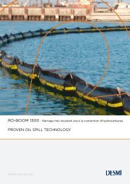
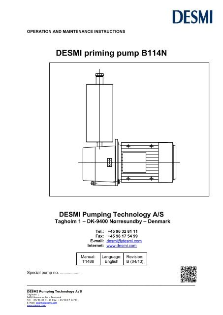
OPERATION AND MAINTENANCE INSTRUCTIONS<strong>DESMI</strong> <strong>priming</strong> <strong>pump</strong> <strong>B114N</strong><strong>DESMI</strong> Pumping Technology A/STagholm 1 – DK-9400 Nørresundby – DenmarkTel.: +45 96 32 81 11Fax: +45 98 17 54 99E-mail: desmi@desmi.comInternet: www.desmi.comManual:T1488Language:EnglishRevision:B (04/13)Special <strong>pump</strong> no. .................__________________________________________________________________________________<strong>DESMI</strong> Pumping Technology A/STagholm 19400 Nørresundby – DenmarkTel: +45 96 32 81 11 Fax: +45 98 17 54 99E-mail: desmi@desmi.comwww.desmi.com
Table of Contents:1. PRODUCT DESCRIPTION ............................................................................................................ 31.1 DELIVERY ........................................................................................................................................ 32. TECHNICAL DATA ..................................................................................................................... 32.1 EXPLANATION OF THE NAME PLATE .............................................................................................. 32.2 TECHNICAL DESCRIPTION .............................................................................................................. 33. INSTALLATION .......................................................................................................................... 43.1 WIRING .......................................................................................................................................... 44. TRANSPORT/STORAGE ............................................................................................................. 45. DISMANTLING .......................................................................................................................... 45.1 ACCESS TO IMPELLER ..................................................................................................................... 45.2 SHAFT SEAL .................................................................................................................................... 45.3 INSPECTION ................................................................................................................................... 56. ASSEMBLING ............................................................................................................................ 56.1 FITTING SHAFT AND SHAFT SEAL ................................................................................................... 56.2 FITTING IMPELLER .......................................................................................................................... 56.3 SHAFT ............................................................................................................................................. 57. FROST PROTECTION.................................................................................................................. 58. DISMANTLING .......................................................................................................................... 69. START-UP ................................................................................................................................. 69.1 STARTING ....................................................................................................................................... 610. INSPECTION AND MAINTENANCE ............................................................................................ 711. REPAIRS ................................................................................................................................. 711.1 ORDERING SPARE PARTS ............................................................................................................. 712. OPERATING DATA ................................................................................................................... 713. EU DECLARATION OF CONFORMITY ........................................................................................ 814. ASSEMBLY DRAWING <strong>B114N</strong> .................................................................................................. 914.1 SPARE PARTS LIST <strong>B114N</strong> ............................................................................................................. 915. DIMENSIONAL SKETCH ......................................................................................................... 10__________________________________________________________________________________<strong>DESMI</strong> Pumping Technology A/STagholm 19400 Nørresundby – DenmarkTel: +45 96 32 81 11 Fax: +45 98 17 54 99E-mail: desmi@desmi.comwww.desmi.com
1. PRODUCT DESCRIPTIONThese maintenance and operation instructions apply to the <strong>DESMI</strong> <strong>priming</strong> <strong>pump</strong>s <strong>B114N</strong>.The <strong>pump</strong>s have 1/2" connections on suction and pressure side. <strong>B114N</strong> is a vacuum <strong>pump</strong> ofthe water ring type, with mechanical shaft seal, bronze shaft, star wheel, and <strong>pump</strong> casing.Max. temperature for standard type is 80°C.The <strong>pump</strong>ed liquid serves as lubricant for the <strong>pump</strong>s and therefore, they do not have to belubricated further.Max. number of revolutions is 3600 RPM. The <strong>pump</strong> is driven by an electric motor, which maybe a standard AC motor, or a DC motor.1.1 DELIVERY- Check on receipt that the delivery is complete and undamaged.- Defects and damages, if any, to be reported to the carrier and the supplier immediatelyin order that a claim can be advanced.2. TECHNICAL DATA2.1 EXPLANATION OF THE NAME PLATEThe <strong>pump</strong>s are equipped with a name plate indicating <strong>pump</strong> type, production week, productionyear, item list number if the <strong>pump</strong> has been sold alone, or an order number, if the <strong>pump</strong> hasbeen sold when built together with another machine.Before putting a <strong>pump</strong> into operation, the suitability of the material combination of the <strong>pump</strong>must always be taken into consideration. In case of doubt, contact the supplier.If the <strong>pump</strong>s are intended for special purposes the following is to be indicated:Pump No. : _________________________________________________Pump type : _________________________________________________Application :_________________________________________________Comment : _________________________________________________2.2 TECHNICAL DESCRIPTIONThe noise level indicated is the airborne noise including the motor. The noise depends on themotor type supplied, as the noise from the <strong>pump</strong> can be calculated as the noise level of themotor + 2dB(A). This noise level applies to <strong>pump</strong>s with electric motors.The permissible loads on the flanges on suction and pressure side are stated in the tablebelow:Pump Fv(N) Fh (N) F(N) Mt (Nm)<strong>B114N</strong> 500 400 640 80______________________________________________________________________________<strong>DESMI</strong> Pumping Technology A/S 3Tagholm 19400 Nørresundby – DenmarkTel: +45 96 32 81 11 Fax: +45 98 17 54 99E-mail: desmi@desmi.comwww.desmi.com
Fv : The max. permissible sum of the vertical forces on the two connections.Fh : The max. permissible sum of the horizontal forces on the two connections. F : The vectorial sum of the two forces Fv and Fh. Mt : The max. permissible sum of torques on the two connections.In connection with the permissible loads on the connections stated in the above table thefollowing is to be observed:2 F calc F 2 M calc M t 2where index "calc" is the values calculated by the user.3. INSTALLATIONThe max. permissible loads on the connections stated in paragraph 2.2 must be observed.At installations <strong>pump</strong>ing hot or very cold liquids the operator must be awarethat it is dangerous to touch the <strong>pump</strong> surface and he is to take the necessarysafety measures.3.1 WIRINGWiring to be carried out by authorized skilled workmen according to the rulesand regulations in force.4. TRANSPORT/STORAGEThe weight, including <strong>DESMI</strong> motor, is indicated in the table below:TypeWeight in kg<strong>B114N</strong>/50 Hz 30<strong>B114N</strong>/60 Hz 31The <strong>pump</strong> is to be stored in a dry area.5. DISMANTLINGThe numbers in brackets refer to the position numbers on the assembly drawing.5.1 ACCESS TO IMPELLERRemove Allen screws (12) and dismantle the end cover (3). Remove the pointed screw (7).The impeller (1) can now be pulled off and inspected.5.2 SHAFT SEALRemove key (11) from the shaft (4). Remove the copper pipes (16) and (27) connected to the<strong>pump</strong> casing. Remove set screws (14) and pull the <strong>pump</strong> casing free of the shaft (4) and theelectric motor and the shaft seal is pulled off the shaft.. Press the seat out from behind the<strong>pump</strong> casing.______________________________________________________________________________<strong>DESMI</strong> Pumping Technology A/S 4Tagholm 19400 Nørresundby – DenmarkTel: +45 96 32 81 11 Fax: +45 98 17 54 99E-mail: desmi@desmi.comwww.desmi.com
5.3 INSPECTIONAfter dismantling as described in 5.1, inspect the impeller, end cover and <strong>pump</strong> casing.Replace the parts, if wear or corrosion is established in areas to such an extent that the <strong>priming</strong>ability of the <strong>pump</strong> is considerably deteriorated, or the <strong>pump</strong> makes more noise than usual.Check the seat in the shaft seal for flatness and cracks. Check rubber parts for elasticity.6. ASSEMBLING6.1 FITTING SHAFT AND SHAFT SEALFit the shaft (4) on the motor shaft. The motor shaft must entirely bottom the hole in the shaft(4). Fit and tighten the pointed screws (6) (first the middle screw). Check that the wobble ofthe shaft, measured as far as possible from the motor, does not exceed 0.07 mm (70 m).Fit the sealing washer (9) in the <strong>pump</strong> casing. Fit the <strong>pump</strong> casing on the motor with screwsand washers (14).Please note which type of rubber is used in the shaft seal bellows. As standard the materialis nitrile, but it might be EPDM which will be damaged by mineral grease. Use soft soap orsilicone grease for EPDM. Before fitting the seat, clean the recess in the cover. Dip the outerrubber ring of the seat in soapy water or grease it with silicone. Now press the seat intoplace with the fingers and check that all parts are correctly imbedded. If it is necessary touse fitting tools, then protect the sliding surface of the seat to prevent it from being scratchedor cut. Lubricate the inner diameter of the rubber bellows on the slide ring with soapy waterand push it over the shaft.Push the slide ring over the shaft with the hand. If the rubber bellows is tight, use a fittingtool and take care that the slide ring is not damaged. If the carbon ring is not fixed, it isimportant to check that it is fitted correctly, i.e. the chamfered/lapped side is to face the seat.The carbon ring can be held by a little grease. When using soapy water on the shaft, thebellows will settle and seat in about 15 minutes and until then tightness should not beexpected. After start, check by viewing the leak hole that there are no leaks.6.2 FITTING IMPELLERFit the key (11) in the shaft and lead the impeller over the shaft. Use an air gap gauge to placethe impeller 0.05 mm from the <strong>pump</strong> casing when tightening the pointed screw (7). Fit the endcover and O-ring (13) with Allen screws (12). Fit the copper pipes (16) and (27) connected tothe <strong>pump</strong> casing.6.3 SHAFTWhen the <strong>pump</strong> has been assembled, check that the shaft rotates freely and without noise.7. FROST PROTECTIONPumps which are not in operation during frost periods are to be drained to avoid frost damage.Alternatively, it is possible to use anti-freeze liquids in normal constructions.______________________________________________________________________________<strong>DESMI</strong> Pumping Technology A/S 5Tagholm 19400 Nørresundby – DenmarkTel: +45 96 32 81 11 Fax: +45 98 17 54 99E-mail: desmi@desmi.comwww.desmi.com
8. DISMANTLINGBefore dismantling the <strong>pump</strong> make sure that it has stopped. Empty the <strong>pump</strong>of liquid before it is dismantled from the piping system. If the <strong>pump</strong> has been<strong>pump</strong>ing dangerous liquids you are to be aware of this and take the necessarysafety measures.If the <strong>pump</strong> has been <strong>pump</strong>ing hot liquids, take great care that it is drainedbefore it isremoved from the piping system.9. START-UPThe <strong>pump</strong> will not function until the feed water tank has been filled with liquid.The liquid also serves as coolant for the shaft seal. In order to protect the shaftseal the <strong>pump</strong> must not run dry.9.1 STARTINGBefore starting the <strong>pump</strong> check that- the shaft rotates freely without jarring sounds.- the feed water tank is filled with liquid.Start the <strong>pump</strong> for a moment to check the direction of rotation. If the direction is correct (i.e. inthe direction of the arrow), the <strong>pump</strong> may be started. Should the <strong>pump</strong> not function asintended, please proceed according to the fault-finding list. Bear in mind, though, that the<strong>pump</strong> was carefully checked and tested at the factory and that the majority of faults stem fromthe piping system.FAULT CAUSE REMEDYThe <strong>priming</strong> <strong>pump</strong> has noor too low capacity1. Wrong direction of rotation2. Piping system choked3. The <strong>pump</strong> is choked4. Suction line leaks5. Suction lift too high6. No water in the feed watertank7. The <strong>pump</strong> is unable todischarge air into thedelivery piping.Change direction of rotationto the direction of the arrowClean or replaceClean the <strong>pump</strong>. Check thecopper pipe between feedwater tank and <strong>pump</strong>, and allfittings on the <strong>pump</strong>Find the leakage, repair thefault. Note: a pressure-tightpiping system is notnecessarily vacuum-tight.Check data sheet Q/H orcontact <strong>DESMI</strong>Fill the feed water tankwith waterThe piping system must bedesigned so that air caneasily escape. A vertical pipefilled with water reduces theairflow considerably.______________________________________________________________________________<strong>DESMI</strong> Pumping Technology A/S 6Tagholm 19400 Nørresundby – DenmarkTel: +45 96 32 81 11 Fax: +45 98 17 54 99E-mail: desmi@desmi.comwww.desmi.com
FAULT CAUSE REMEDYThe <strong>priming</strong> <strong>pump</strong> usestoo much power1. Foreign body in <strong>pump</strong>2. Electric motor is running on2 phasesDismantle the <strong>pump</strong>, removethe causeCheck fuses, cableconnection and cable10. INSPECTION AND MAINTENANCEInspect the shaft seal in <strong>B114N</strong> for leaks at regular intervals.- Before any inspection of a <strong>pump</strong> without guard check that the unit cannot be startedunintentionally.- The system is to be without pressure and drained of liquid.- The repairman must be familiar with the type of liquid which has been <strong>pump</strong>ed as wellas the safety measures he is to take when handling the liquid.11. REPAIRS11.1 ORDERING SPARE PARTSWhen ordering spare parts please always state <strong>pump</strong> type and <strong>pump</strong> No. (indicated on thename plate of the <strong>pump</strong>). See also spare parts drawing with item Nos and part names. Seeassembly drawing.12. OPERATING DATAThe powers indicated in the table below constitute the max. power consumption of the <strong>pump</strong>.The following working pressures are allowed:TYPEPRESSUREbarPowerkW<strong>B114N</strong> 2 2,6______________________________________________________________________________<strong>DESMI</strong> Pumping Technology A/S 7Tagholm 19400 Nørresundby – DenmarkTel: +45 96 32 81 11 Fax: +45 98 17 54 99E-mail: desmi@desmi.comwww.desmi.com
13. EU DECLARATION OF CONFORMITY<strong>DESMI</strong> Pumping Technology A/S, hereby declare that our <strong>pump</strong>s of the type <strong>B114N</strong> aremanufactured in conformity with the following essential safety and health requirements in theCOUNCIL DIRECTIVE 2006/42/EC on machines, Annex 1.The following harmonized standards have been used:EN/ISO 13857:2008 Safety of machinery. Safety distances to prevent dangerzones being reached by the upper limbsEN 809 + A1Pumps and <strong>pump</strong> units for liquids – Common safetyrequirementsEN/ISO12162+A1:2009 Liquid <strong>pump</strong>s – Safety requirements – Procedure forhydrostatic testingEN 60204-1:2006 Safety of machinery – Electrical equipment of machines (item4, General requirements)Pumps delivered by us connected with prime movers are CE-marked and comply with theabove requirements.Pumps delivered by us without prime movers (as partly completed machinery) must only beused when the prime mover and the connection between prime mover and <strong>pump</strong> comply withthe above requirements.Nørresundby, Jan 25, 2013Kurt Bech ChristensenTechnical Director<strong>DESMI</strong> Pumping Technology A/STagholm 19400 Nørresundby______________________________________________________________________________<strong>DESMI</strong> Pumping Technology A/S 8Tagholm 19400 Nørresundby – DenmarkTel: +45 96 32 81 11 Fax: +45 98 17 54 99E-mail: desmi@desmi.comwww.desmi.com
14. ASSEMBLY DRAWING <strong>B114N</strong>OPTION FOR TRYKKONTAKT:PUMPE R ME D MANOME TREPRE SSURE SWITCH OPTION:PUMPS WITH GAUGE S1091730OPTION FOR MAGNE TVE NTIL.POS. 15 OG 17OPTION FOR SOLE NOID VALVETO BE MOUNTE D IN PIPINGBE TWE E N POS. 15 AND 17313433OPTION FOR TRYKKONTAKT:PUMPE R UDE N MANOME TREPRE SSURE SWITCH OPTION:PUMPS WITHOUT GAUGE S313233DISCHARGE ON MAIN PUMPTRYKSIDE PAA HOVE D-PUMPEDISCHARGE ON MAIN PUMP8133151174692 12 14 150. 05AFSTAND SIKRESENSURE GAP WITHFLAT FEELER GAUGE359 0 L - 2 B 3 - B 5w . lo c k e d b e a rin gin d riv e e n dKUN PAA SPACE R-PUMPE RONLY ON SPACE R PUMPS152120191817162217232425262728SUGE SIDE PAAHOVE D-PUMPESUCTION ONMAIN PUMP14.1 SPARE PARTS LIST <strong>B114N</strong>1 Impeller 14 Set screw/washer 27 Copper pipe2 Pump casing 15 Angle nipple 28 Angle nipple3 End cover 16 Copper pipe 29 Fitting4 Shaft 17 Hexagon nipple 30 Magnetic valve *5 Shaft seal 18 Bushing 31 Pressure switch*6 Pointed screw 19 Filter 32 Muff7 Pointed screw 20 Hexagon nipple 33 Nipple8 Feed water tank 21 Nonreturn valve 34 Muff-tee9 Sealing washer 22 Pipe clamp 35 Motor10 Pipe plug 23 Muff-tee11 Key 24 Hexagon nipple12 Allen screw 25 Red. nozzle13 O-ring 26 Hexagon nipple*) OPTION______________________________________________________________________________<strong>DESMI</strong> Pumping Technology A/S 9Tagholm 19400 Nørresundby – DenmarkTel: +45 96 32 81 11 Fax: +45 98 17 54 99E-mail: desmi@desmi.comwww.desmi.com
48414015. DIMENSIONAL SKETCH50 Hz: 40560 Hz: 430TRYKSTUDS(DISCHARGE):1/2"BSP26550 Hz:90S260 Hz:90L212590<strong>DESMI</strong><strong>B114N</strong>1405650 Hz:10060 Hz:125SUGESIDE PAAHOVED-PUMPE(SUCTION ONMAIN PUMP):1/2"BSP______________________________________________________________________________<strong>DESMI</strong> Pumping Technology A/S 10Tagholm 19400 Nørresundby – DenmarkTel: +45 96 32 81 11 Fax: +45 98 17 54 99E-mail: desmi@desmi.comwww.desmi.com