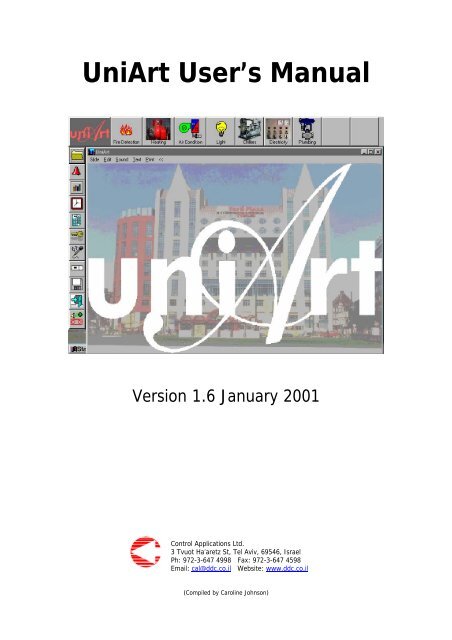
UniArt User's Manual - SUPERBRAIN smart controller
UniArt User's Manual - SUPERBRAIN smart controller
UniArt User's Manual - SUPERBRAIN smart controller

Create successful ePaper yourself
Turn your PDF publications into a flip-book with our unique Google optimized e-Paper software.
ContentsLIST OF FIGURES ..........................................................................................1SECTION 1: GETTING STARTED ...................................................................3CHAPTER 1 GENERAL .......................................................................................41.1 Software Installation Instructions ..............................................41.2 Configuring Systems Modules....................................................5SECTION 2: WORKING WITH UNIART ........................................................11CHAPTER 1 TASK BARS... .................................................................................12CHAPTER 2 VERTICAL TASKBAR........................................................................132.1 Group......................................................................................132.1.1 Creating and editing logical groups............................................132.1.2 Group Properties ......................................................................142.1.3 Edit ....... .................................................................................162.1.4 Edit Graphics ...........................................................................212.1.5 Edit Groups .............................................................................292.1.6 Run Mode................................................................................302.2 Alarms.....................................................................................332.2.1 Current Alarm Report ...............................................................332.2.2 Current Events Report ..............................................................352.2.3 Edit Alarms ..............................................................................352.2.4 Fast Build ................................................................................382.2.5 Alarm Report History ................................................................402.2.6 Historical Event Report .............................................................402.2.7 Phone and Mail Messages .........................................................402.2.8 Print Alarm List ........................................................................402.3 Trend Reports..........................................................................412.3.1 Creating and editing trends ......................................................412.3.2 Graphical display of trends .......................................................422.3.3 Text display of trends...............................................................452.3.4 Deleting data ...........................................................................462.4 Time Program/Time dependant actions ..................................... 472.4.01 Send Print Report.....................................................................472.4.02 Show Errors.............................................................................472.4.03 Send All...................................................................................472.4.04 Time Program List....................................................................472.4.05 Duplicity Check ........................................................................502.4.06 Send .......................................................................................512.4.07 Calendar..................................................................................522.4.08 Export to HTML........................................................................532.4.09 CPU Clock................................................................................532.4.10 Sort.........................................................................................532.4.11 See Time History......................................................................552.4.12 Sort the list..............................................................................55
2.4.13 Print........................................................................................552.4.14 Fast Edit ..................................................................................552.4.15 Exit .........................................................................................562.5 Calendar..................................................................................572.6 Password Setting .....................................................................572.7 Voice Messages........................................................................582.8 Special Programming Features ..................................................582.8.1 Check Active ............................................................................582.8.2 Send to CPU ............................................................................602.8.3 Build Tree................................................................................612.8.4 CPU Clock................................................................................612.8.5 Run BAK ..................................................................................612.8.6 Mapped Y Register ...................................................................612.8.7 Run Compile ............................................................................612.8.8 Exit .........................................................................................612.9 Settings...................................................................................622.10 Exit .........................................................................................632.11 Last icon..................................................................................63SECTION 3: HORIZONTAL TASK BAR ..........................................................64APPENDIX A – NETWORK (includes PC’s, COM’s, Ports and Controllers) ..........67
List of FiguresCD-ROM icon in “My Computer”............................................................1.01PRJSETUPin C:\<strong>UniArt</strong>\Bin....................................................................1.02<strong>UniArt</strong> Setup.......................................................................................1.03UniStarter location ..............................................................................1.04Appserver menu icon...........................................................................1.05Netserver menu icon ...........................................................................1.06<strong>UniArt</strong> Communication Appserver .........................................................1.07<strong>UniArt</strong> Communication Netserver ..........................................................1.08NetControllers.....................................................................................1.09NetController Menu .............................................................................1.10CPU Properties....................................................................................1.11Netserver IP address ...........................................................................1.12Main Menu icon...................................................................................2.01Vertical Taskbar ..................................................................................2.02Groups Menu ......................................................................................2.03Edit Menu Box ....................................................................................2.04Group Properties.................................................................................2.05Operational Planning Document ...........................................................2.06Group Menu .......................................................................................2.07I/O Configurations...............................................................................2.08Edit Group Menu- Extended .................................................................2.09Type/Eng/f(x).....................................................................................2.10CPU/File/Points/Port/Level/Display limits ...............................................2.11Conversion Formulae...........................................................................2.12Linear Software ..................................................................................2.13Fill Multi Lines.....................................................................................2.14Edit Group Menu toolbar......................................................................2.15File sub-menu.....................................................................................2.16Copy sub-menu...................................................................................2.17Replaces sub-menu .............................................................................2.18Edit Graphics ......................................................................................2.19Group properties sub-menu .................................................................2.20Unit Properties....................................................................................2.21Zoom Editor........................................................................................2.22Edit Unit.............................................................................................2.23Unit Properties for 1,1,Ai......................................................................2.24Color Effects .......................................................................................2.25Add sub-menu ....................................................................................2.26Vessel Editor.......................................................................................2.27Gauge Editor- general .........................................................................2.28iGauge Editor- colors/values .................................................................2.28iiSlide Editor- general............................................................................2.29iSlide Editor- colors ..............................................................................2.29iiAdd Label...........................................................................................2.30Animation Selector ..............................................................................2.31Group Menu Toolbar............................................................................2.32Edit Groups sub-menu .........................................................................2.33Point Menu .........................................................................................2.34Set Unit..............................................................................................2.35Unit Properties 2 .................................................................................2.36Analog Value Slider .............................................................................2.37Digital Value Buttons ...........................................................................2.38Run Mode Toolbar...............................................................................2.391
Alarm Manager Menu ..........................................................................2.40Current Alarms Report.........................................................................2.41Key Sorts ...........................................................................................2.42Edit Alarms.........................................................................................2.43Alarm Properties Editor........................................................................2.44Alarm Properties Editor – Advanced ......................................................2.45Fast Build ...........................................................................................2.46Quick Edit – add .................................................................................2.47Quick Edit – delete ..............................................................................2.48Historical Alarms .................................................................................2.49Select Trend and sub-menu .................................................................2.50Trends Editor .....................................................................................2.51Foyer Graphical Data...........................................................................2.52Trend Toolbar.....................................................................................2.53Trend Toolbar sub-menu .....................................................................2.54Timing ...............................................................................................2.55Select Time ........................................................................................2.56Foyer Text Data ..................................................................................2.57Cut Trend Data ...................................................................................2.58Time Program Menu............................................................................2.59Time Program List...............................................................................2.60Time Program Editor ...........................................................................2.61Time Program Check A ........................................................................2.62Time Program Check B ........................................................................2.63Send Time Program.............................................................................2.64Calendar ............................................................................................2.65Send Clock .........................................................................................2.66Time Program Sorted List ....................................................................2.67Time History.......................................................................................2.68Password Setting ................................................................................2.69Access Level Setup..............................................................................2.70CPU Utilities Menu...............................................................................2.71Check Active ......................................................................................2.72Change CPU number ...........................................................................2.73Compile and Send programs ................................................................2.74Setting ...............................................................................................2.75Horizontal taskbar ...............................................................................3.01AutoZoom Properties...........................................................................3.022
SECTION 1GETTING STARTED
Chapter 1- GENERAL<strong>UniArt</strong> is a PC-based, user-friendly SCADA software package intended formonitoring and controlling DDC/PLC <strong>controller</strong>s.<strong>UniArt</strong> establishes a natural Man Machine Interface (MMI) between thecontrol staff and the site’s control system.<strong>UniArt</strong> is especially designed to monitor and control heating, ventilation andair-conditioning (HVAC) systems as well as electrical, energy, fire detection,lighting and extinguishing systems.The communication server that connects the <strong>UniArt</strong> to the <strong>controller</strong> is thecentre of the system. This server sets the communication protocol betweenthe computer/PC and the <strong>controller</strong>.The standard system includes the following items:• Communication server• Menu• Alarm• Miscellaneous<strong>UniArt</strong> uses it’s own database. Each page of the database can contain up to40 groups and each group can be connected to 80 points.1.1 Software Installation InstructionsNOTE: Close down all applications already running in Windows as this may conflict withthe set-up procedure.Insert the CD to the CD drive. The program should run automatically.If not, follow these steps:a. Double-click on “My Computer” icon on the Desktop (see Figure 1.01)b. Double-click on CD-ROM iconc. Find the <strong>UniArt</strong>.exe icon and double-clickd. Follow the program’s installation instructionsDouble-click on CD-ROM iconFigure 1.01 – CD-ROM icon in “MyComputer”4
1.2 Configuring System ModulesThis section describes how to define, modify and configure the <strong>UniArt</strong>modules that are to be run by the computer.a. Double-click on “My Computer” icon on the Desktopb. Double-click on the icon for the disk drive where <strong>UniArt</strong> is installedc. Double-click on “<strong>UniArt</strong> directory” icond. Double-click on “BIN” folder icone. Double-click on “PRJSETUP” icon (Figure 1.02)Figure 1.02 -PRJSETUP inC:\<strong>UniArt</strong>\BinThe screen that appears in Figure 1.03 offers the user the basic functionsneeded to operate the <strong>UniArt</strong> system.Figure 1.03- <strong>UniArt</strong> Set-Up5
The Active frame at the top of the screen shows the programs that havebeen selected and are currently running.The files under the title File Name are the default items. They include:appserver.exe 1mainmenu.exealarmrun.exetrendrun.exeNOTE: If you are connected via ethernet you must changeappserver.exe 1 to netserve.exe in Create New Item.The column entitled Wait shows the delay time between running programsso as to prevent all programs being run together and creating congestion.The default time is 5 seconds.The List frame in the middle of the screen shows options that may be addedto the system, such as additional communications ports (use scrollbar whenneeded). Once items are selected they will appear in the Active frame.In order to select/activate a new item:a. highlight the relevant file from the List frame by clicking on itb. press the Add button to the right of the List menu.Items may be removed from the Active frame only. In order to do this,highlight the relevant file and press the Remove button to the right of theActive frame.Advanced users may add items that do not appear as default by using theCreate New Item frame in the lower section of the screen. They may alsoset parameter, delay time and priority.EXAMPLE OF DEFAULT ITEMS:appserver.exe 1…Once the <strong>UniArt</strong> software is installed it will appear in the program section ofthe main Windows menu. Highlighting this folder and placing the cursor overthe arrow on the right-hand side will show the UniStarter program sub-menu,(see Figure 1.04). <strong>UniArt</strong> icons will also appear along with the other icons inthe bottom right-hand corner of the screen next to the clock.6
Figure 1.04 –UniStarter locationa) For RS232/485 connection, place the cursor over the Appserver menuicon (Figure 1.05) and click on the right mouse button.b) For TCP/IP connection, place the cursor over the Netserver menu icon(Figure 1.06) and click on the right mouse button.Figure 1.05 – Appserver menu iconFigure 1.06 – Netserver menu iconThe following options will appear:ABOUT: details about currently installed versionSHOW MANAGER PAGE: for use by CAL personnel onlySHOW DEBUG PAGE: allows selection of active <strong>controller</strong>sLEVEL DEFINITION: allows security access level to be definedEXIT: to close the programSelect the Show Debug Page. Only authorised users will be able to accessthis page by entering their password.7
The menus that appear in Figures 1.07 and 1.08 will allow you to select theactive <strong>controller</strong>s in the system.How to use:1. Connect and define the CPU number of the <strong>controller</strong>.2. Remove the tick from the Demo box.3. Place a tick in the box(es) next to the relevant CPU(s).4. Wait for the CPU to turn green and so confirm that the <strong>controller</strong> isactive.Here, different colours indicate the different statuses of the <strong>controller</strong>s.Green: the <strong>controller</strong> is activeRed: the <strong>controller</strong> is inactive (after 10 tries)Pink: the system is trying to connect (will try 10 times)Yellow: monitoring the <strong>controller</strong> statusBlue: data is being transmittedLight green: the <strong>controller</strong> was selected, but no connection has beenattemptedAPPSERVERFigure 1.07 – <strong>UniArt</strong>communication Appserver8
Make sure that the system is not in demo mode, by removing the tick from theDemo box at the top right-hand side of the screen.The Special All and Reset On buttons at the bottom of the screen are forCAL personnel only and should not be adjusted.NETSERVERFigure 1.08 – <strong>UniArt</strong>communicationNetserverClick on File and then NetController at the top of the <strong>UniArt</strong> CommunicationNetserver screen to bring up the screen in Figure 1.09.Figure 1.09 –NetControllers9
Chapter 1 – TASK BARS• The horizontal bar features a set of icons that represent groups ofcritical functions.• The vertical bar is smaller than the horizontal and is used for editingfunctions, creating alarms, creating groups, setting times and more.See map of the task bars at the bottom of the page.Once the programs are loaded their respective icons appear on the bottomright-hand side of the screen in the task tray next to the computer’s clock.Click with right mouse button on the main menu icon (Figure 2.01).Figure 2.01 – Main Menu iconThe following menu will appear:ABOUT: details about currently installed <strong>UniArt</strong> softwareNORMAL UNI BAR: will show the task bars only when the cursorapproaches the top left of the screenSHOW UNI BARS: allows continuous display of task barsHIDE UNI BARS: hides the taskbarEXIT: to close the program12
Chapter 2 – VERTICAL TASK BARGroupsAlarm ManagerTrend MenuTime Program ListCalendarPassword SettingVoice MessagesCPU UtilitiesSettingsExitCAL Personnel OnlyFigure 2.02 – Left Task Bar2.1 - Folder2.1.1 CREATING AND EDITING LOGICAL GROUPSLogical groups are made up of input points, output points and parameterswhich are defined by their addresses on the <strong>controller</strong>. They are displayedon the screen as groups of points that have a functional relationship.Select the GROUPS icon to bring up the following screen entitled GroupsMenu, (see figure 2.03). This list will appear blank when used for a newsystem.13
Figure 2.03 – Groups MenuTo edit any of the lines in the Groups Menu, place the cursor over the lineand click on the right mouse button. The following box should appear,(Figure 2.04).Figure 2.04 – Edit menu box2.1.2 GROUP PROPERTIESSelect Group Properties in the Edit Menu box, (figure 2.04) to make thebox in Figure 2.05 appear.NOTE: This box will appear blank, as in figure 2.05, if the line is not in use.Figure 2.05 – Group properties14
Name: Give a name to the group, eg. A/C No.1.Group Number: Line number in Groups Menu box.Acc. (access) Level: to be assigned by the supervisor to limit access todisplaying group data.Reset will return all levels to their default as defined in Chapter 9 – Settings.Picture Name: Press the change button to select an image either fromControl Applications Ltd.’s library, user’s library or another source. This willserve as background picture for the displayed group.Jump to page: enables the user to ‘jump’ straight to a defined page bydouble-clicking on that line in the Group Menu. This allows for easy accessto pages when the user is working with many pages.View as table: Can view data as a table rather than a picture.Font Color: to change the color of the group name.Advanced: for Control Applications Ltd. personnel only.15
2.1.3 EDITThe user creates groups in his/her own logical manner so that the points onsite can be viewed from his/her computer.Each group represents a collection of points, (for example these can be pointsof a specific device or a zoom).Choose a blank line in the Group Menu (Figure 2.03) and select EDIT fromthe Edit Menu box (figure 2.04).For this example, Line 1 the AHU 1-1 Foyer, has been chosen.Figure 2.07 – Edit GroupMenui. Fill in the name of the group in the Group Name box.ii. Fill in the Name of each point, one per line.iii. Click on the desired line in the Type column and a menu box will appear(see figure 2.08) for easy selection of I/O configuration.A. In = analog inA. Out = analog outD. In = digital inD. Out = digital outPar. = parameterD. Par. = digital parameterFigure 2.08– I/O configurationsiv. Click on the desired I/O point to select.v. Fill in the CPU column with the number of the <strong>controller</strong>.NOTE: groups may include points from more than one <strong>controller</strong>.vi. The File column refers to the program associated with the point. Thisis only relevant when the point is defined as a parameter (Par.).16
vii. Point refers to the number of the I/O point.NOTE: OUT points are numbered n (1-32) and IN points are numberedn+50 (51-83).viii. Eng. refers to the engineering unit.Select the suitable unit where relevant by clicking on the desired lineand choosing one of the options that appear in the menu box.NOTE: Digital points will not need this.The Advanced button at the bottom of the screen enables the user to accessadditional editing options (Figure 2.09).Figure 2.09 – Edit group menu-extendedThe Access Level box in the top right hand corner of the screen allows theuser to choose an access level for the group. Once an access level has beenselected the user will be required to enter a password in order to access thisediting option, (see Chapter 2.6 – Password Settings for more details).Access levels may also be established for each point in the column headedLevel.Reset Acc. Level:There are two columns entitled Protect:• Ticking the left boxes (P) will lock the specific points so that the datamay not be changed.• Ticking the right boxes (H) will hide the specific points on any graphicdisplay of the system.Click on the titles of the columns (eg Type or CPU) to make the boxes infigures 2.10 and 2.11 appear. These boxes allow the user to fill in the samevalue for many lines as oppose to one at a time.17
Figure 2.10– Type/Eng./F(x) value box• Click on Type, Eng. andF(x) to make the box infigure 2.10 appear.• Type in the lines you wouldlike to fill.• Click OK• For Type, a menu box with I/O point options will appear.• Define the same I/O point for all chosen lines.• Click on CPU, File, Points, Port, Level and Display limits so the boxin Figure 2.11 appears.• Select the lines you wouldliketo fill and place number in theValue box, (for Display Limitsselect min. and max. value).• Press OK.Figure 2.11- CPU/File/Points/Port/Level/Display limits value boxFor Port address see Appendix A.Fill All: to include all lines that you have selected. If this option is notchosen all lines with the value of zero will remain with a value of zero.Ignore Empty Names: lines that have not been named will not be altered.Clicking on any line under the F(x) column will make the box in Figure 2.12appear.Figure 2.12 – Conversion formulaeThis box enables the user to define the A/B values and to convert the unitsmeasured by the <strong>controller</strong> to those to be displayed on the PC (<strong>UniArt</strong>).18
The AB Solver button converts measured units to displayed units (eg., °C to°F or V to ppm).Figure 2.13 – Linear SolverEg.) Converting °C to °F• Enter 0 and 50 in the Measuredboxes,(the <strong>controller</strong> measures temperaturesbetween 0-50°C).• Enter the equivalent convertedmeasurements in the Shown boxes,(32°F and 122°F).• The AB Solver immediately showsvalues A=1.8 and B=32.The Auto Fill button brings up a screen (Figure 2.14) that allows you to fill inall of the columns for multiple lines.Figure 2.14 – Fill Multi LinesThe Colours button gives you the option to colour the displayed parameters.Pressing this button again returns you to the regular screen.Colour options:High Value: any value greater or equal to the chosen number will displaythe chosen colour.Disp. High: text to be displayed when the value is higher than the highvalue.19
Disp. Inter.: text to be displayed when the value is between the high andlow values.Low Value: any value lower than the chosen number will display the chosencolour.Disp. Low: text to be displayed when the value is lower than the low value.Disp. Format: uses a box similar to that in figures 2.10 and 2.11 allowingyou to choose the format that you want values to be displayed in.Use #’s and/or 0’s to set the display format.#: keeps the place of a number to be displayed0: places 0 where there is no numberEg.) ####.### = 234.560000.000 = 0234.560#.# = if the value here is zero nothing will be displayed0.0 = 0.0Time can be displayed HH:MMEdit Group Menu Toolbar:Figure 2.15 – Group Menu ToolbarPress FILE to bring up the following sub-menu.Figure 2.16 – File sub-menuEXCEL PCU RULES: Use for Control Applications Ltd. personnel only.ABOUT: Information about the <strong>UniArt</strong> version that you are using.SAVE: standard save feature.Press COPY to bring up the following sub-menu.Figure 2.17 – Copy sub-menuCOPY ANOTHER GROUP: to copy a complete group to current group.COPY UNITS FROM GROUP: copies units (at least 2) from another groupto the current group.Press REPLACES to bring up the following sub-menu.Figure 2.18 – Replaces sub-menu20
REP. CPU: allow you to change the CPU definition.REP. STR: allows you to replace a word(s) with another word(s).CHANGE SERVER: allows you to change the communication server.PRINT and RUN to be used as in other programs.2.1.4 EDIT GRAPHICSSelect Edit Graphics option from Edit Menu box (Figure 2.04). You will beasked to enter a password. If a picture was chosen in the Group Propertiesbox (Figure 2.05) the screen will appear with that picture and a list of the I/Opoints in the top left corner. Now you have to drag these points to theirrelative place on the picture. This has been done in Figure 2.19.If no picture was chosen the screen will appear blank with a list of I/O pointsand the picture can be chosen from here.Figure 2.19 - Edit GraphicsFigure 2.20 – Group Properties sub-menuGROUP PROPERTIES: opens box in Figure 2.05.21
SEARCH UNIT: enables you to find units easily. You will have the followingoptions for each point once clicking here.• Reset: Clicking on this button will make the point on the diagram turnred and return to the top left corner.• Undo Size: Clicking on this button will return the point to it’s originalsize.• Search: Clicking on this button will make the point turn red.ADD UNIT: makes the box in Figure 2.21 appear. Fill in the required unitproperties.Figure 2.21 – Unit propertiesThe Advanced button, depressed here, allows the following options:Access level: to choose an access level for the point.Port number: see Appendix A.Display Limits: to choose the format in which the point is to be displayed(see page 20 for examples).F(x) type: conversion formulae and definition of A/B values.Operational Display format (how to display the units):Normal (sliding gauge), Valve, Gauge or Discrete (option to setthree buttons representing 3 values).Protected: lock the point so that the data cannot be altered.Hidden: hide the point in any graphic display.Excel Rules: for use within Israel only.ADD ZOOM: makes the box in Figure 2.22 appear.22
Figure 2.22 - Zoom EditorThe Zoom feature is a means of linking related pages allowing you to jumpbetween them for easy access.Press Select Group to make the Groups Menu (figure 2.03) appear.Double-click on the group that you want to jump to from this page andchoose how you would like the zoom to be displayed.If you wish to view the zoom as a picture, choose a related picture from yourfile by pressing on the Change picture button.ADD LABELS TO ALL UNITS: makes the name of the points appear.RESET UNIT SIZE: resets the sizes of all units to the default.RESET ALL UNITS: resets the sizes of all units and returns them to theiroriginal position.RESET LEVELS: resets the access levels for the units to zero.SNAP TO GRID: you will have to enter a number for the vertical andhorizontal axes. The number that you enter is the number that the screen isdivided by, eg) if you enter 10 for the horizontal resolution, the screen is thendivided into 10 columns. All points are then placed in the top left handcorner of closest cell.The points are displayed on the diagram in the format CPU, Point, Type,eg., 1, 1, Ain.Click with the right mouse button on any of the points on the diagram tochange the properties of that particular point. The menu in Figure 2.23 willappear.Figure 2.23 – Edit UnitEDIT UNIT: allows you to edit the properties of individual units.23
Figure 2.24 – Unit properties for 1, 1, Ai.(for Advanced settings see explanation of Figure 2.21).COLOR EFFECTS: click to make the box in Figure 2.25 appear.Figure 2.25 – Color effects for 1, 1, Ai.• Enter normal operating values in the two boxes on the right.• Under Display enter the text that you would like to appear when thevalue is less than desired, at normal operation and more than desired.• One click in the boxes under Color will make a regular colour paletteappear. Choose colours for the relevant operating levels.• Use Flood Fill gives you the option to fill an area with a solid blackoutline with a particular colour. Select if you would like the area toflash by placing a tick in the Blink box. To activate press SelectArea. This will return you to the editing screen. Click on the area tobe filled. This area will flash to show that it has been selected. Clickon the right mouse button to return to the box in Figure 2.25 andpress OK.NOTE: - Reset colors will make all values and colours return to default.Eg., (1, 1, Ai)Normal operating levels are between 20°C and 30°C.When the value is greater than 30°C it will display red, when the value is lessthan 20°C the point will be blue and when it’s operating within the normalrange the point will be yellow.24
RESIZE: allows you to change the size of the point by dragging the arrows inthe corners of the box.COPY SIZE and PASTE SIZE: allows you to copy the size of a specific pointand then paste it in another place on the diagram.RESET SIZE: changes the size back to default.ADD: place cursor on arrow to the right. The following sub-menu willappear.Figure 2.26 – Add sub-menuADD VESSEL: click so the box in Figure 2.27 appears.This option allows you to add a vessel such as a tank or boiler to yourdiagram.Choose the colour of the area that is already filled (Fill color) and the areathat is not filled (Not filled color).Select the direction you would like the vessel to be filled (Filling direction).Values will be filled in automatically for filling L to R, R to L, top to bottom orbottom to top.Figure 2.27 –Vessel EditorMove the scroll bar to check the filling direction.If you wish that the vessel be filled at an angle fill in the values manually.Total Points indicates the number of red points that are located on thediagram to the left. These points may be dragged to change the shape ofthe vessel.25
Reset returns all values to their default.ADD GAUGE: This option allows you to add a gauge to the diagram.• click Add Gauge so the box in Figure 2.28i appears.• choose a suitable gauge.• choose knobs and hands.• Click Colors/Values option so the box in Figure 2.28ii appears.• Choose value color (current value), scale color (numbers on thescale), knob plate color (knobs) and background picture (fromfile).Figure 2.28i – GaugeEditor-generalFigure 2.28ii – GaugeEditor-Colors/Values.ADD ANIMATION: click to make Figure 2.31 appear.26
Figure 2.31 – AnimationSelector.Select the appropriate picture to be added to the point by clicking on it andthen on OK.The picture will appear in the top right corner of the screen and can bedragged using the mouse to it’s desired position.NOTE: some of the objects have parts that move either clockwise or anticlockwise.Place the cursor on the picture and click once with the right mouse button.This will enable you to Edit, Find Unit, Resize, copy size, paste size anddelete animation.ADD SLIDER: allows you to add a slider to your diagram.Styles (Figure 2.29i):• Choose slider direction eg., up/down or left/right – Slider direction.• Choose the Frame style.• Choose scale to be above/below or to left/right of the bar – visiblescale.• Choose Inverse Direction to change the direction of the slider.27
Figure 2.29i – SlideEditor – generalColors (Figure 2.29ii):• Choose value color (current value), scale color (numbers on the scale),knob color (knobs), back color (background colour), frame brightcolor and frame shadow color (two colours of the frame).Figure 2.29ii – SlideEditor - ColorsADD LABEL: enables you to add a label to any point.Allows you to add a label to any point.Figure 2.30 – Add label28
• High Text will appear when the value is higher than the High Value.• Low text will appear when the value is between the High Value andHide Value.• Values lower than the Hide Value will be hidden.• Select desired colours.ADD REAL TIME GRAPH: enables you to add a line graph to track theprogress of certain points, (usually analog).After adding graph press run to activate.DELETE UNIT: to remove the unit.CANCEL: standard cancel function.Toolbar:Figure 2.32 – Edit Group Menu ToolbarPress FILE for the following options:SAVE: normal save functionRESTORE: will restore all data changed since last save.EXIT: to leave the edit page.Press PRINT and RUN to be used as in other programs.Press EDIT for the Group Properties sub-menu, as in Figure 2.20.2.1.5 EDIT GROUPSFigure 2.33 – Edit groups sub-menuSelect Edit Groups option from Edit Menu box (Figure 2.4) to bring up thebox in Figure 2.33.This menu allows you to delete, copy and paste groups.29
2.1.6 RUN MODEDouble click on any line in the Groups Menu in Figure 2.03 to run thatparticular group. Alternately, you can get to this screen via the Runcommand on the Edit Group Menu toolbar in Figure 2.15.Click with the right mouse button on any point to make the following menuappear.Figure 2.34– Point MenuEDIT TIME PROGRAM: Selecting this option will make the Time ProgramEditor in Figure 2.34 appear. See Chapter 2.5.04 for details on setting timeprograms.CALIBRATE UNIT: Select this option to make the box in Figure 2.35 appear.This option allows you to make fineadjustments to each point for optimalfunctioning.Figure 2.35 – Set UnitCurrent Value: the displayed value.Enter CPU/Point and Port numbers (For Port address see Appendix A).Offset: the difference between the real value and the displayed value.Reset: to reset the last calibration.Reset CPU: to reset all the points. For Control Applications Ltd. personnelonly!!Exit: to leave this screen.SHOW UNIT DETAILS: select this option to make the box in Figure 2.36appear.A description of each text box can be found in Chapter 2.1.3.30
Figure 2.36 – Unit Properties 2Double-click on any analog point or parameter to make theslider in Figure 2.37 appear.This enables you to manually change the value of the point.Figure 2.37 – Analog Value SliderDouble click on any digital point to make the following window appear.Figure 2.38 - Digital Value buttonsThis window allows you to turn a particular point on or off.NOTE: The point on the graphic display turns yellow when manually adjusted.The toolbar in run mode appears as follows:31
Figure 2.39 – Run Mode ToolbarSlide: Press this button and then resize the window to place scroll bars atthe right and bottom. The window can also be resized by dragging it’scorners, but data may be omitted if the screen is reduced too much.Edit: returns you to Edit Graphics screen in Figure 2.19.Sound: Play: to play any prerecorded messages.Record: opens a standard Windows recorder and can be used torecord messages eg) explanation of the system.Clicking on the back arrow returns you to the last screen you visited.32
2.2 - AlarmsThe second icon on the vertical task bar represents the Alarm Manager. Thisoption will enable you to create and monitor alarms. Click on the icon tobring up the box in Figure 2.40.Figure2.40 –AlarmManagerMenu2.2.1 CURRENT ALARM REPORTPress the Current Alarm Report button in Figure 2.40 to make the box inFigure 2.41 appear.This screen allows you to see all current alarms, including those that havebeen acknowledged but not yet fixed.Figure 2.41 – Current Alarms Report33
Name: name of the alarm.Priority: determines the level of priority for reporting alarms. This numberranges between 1-99 (where 99 has the highest priority level).Received Time: displays the date and time that an alarm was received.Ack. Time: displays the date and time that the alarm was acknowledged.Ack. By: the name of the person who acknowledged the alarm will appearhere if an access level and password were required to acknowledge thealarm.The following options allow you to display the alarm messages in differentways:Text/Show Msg: makes text message appear. Eg, text may be instructionsas to what to do when that specific alarm is ringing.Voice/Play Msg: plays sound/voice message.Grp: runs the group in which the current alarm is located.Current Alarm Report Toolbar:The toolbar is located above the Alarm Report table.1. The first button on the left shows a door allowing you to exit the screen.2. The second button to the left allows you to delete the alarm. This optionis for debugging and testing purposes only. You will be required to enter apassword for Access Level 100 (Control Applications Ltd. personnel only).3. The third button is used tosort alarms or search for aparticular alarm. Press thisbutton or the word Sort on thetoolbar to bring up the screen inFigure 2.42.Alternately, clicking on theheadings of each column in theCurrent Alarms Report will sortthe data in either ascending ordescending order.Figure 2.42 – Key Sorts34
Query name: enter part of the alarm name to search.Name: full name of the alarm.Priority: sort the data by priority level.Received time: sort data by the time the alarm was received.Acknowledged time: sort the data by the time the alarm wasacknowledged.Fixed time: sort the data by the time that the alarm was fixed.Name of acknowledging party: find the alarm by the name of the personwho acknowledged it.4. To Print press the fourth button or enter Print via File on the toolbar.5. For use by Control Applications Ltd. personnel only.6. Full Desc.: allows the full name description to be displayed by removingthe Priority and Received Time columns.2.2.2 CURRENT EVENTS REPORTPressing on this button will make a screen similar to that in Figure 2.41.They differ in that here current events are reported not current alarms.When an alarm goes off it will be reported immediately by flashing on yourscreen. When an event occurs it will be listed in this table but will not popup on the screen.2.2.3 EDIT ALARMSClick on this button to make the following box appear. Note that theAdvanced button on the bottom of the screen has been pressed to displayadditional options.Figure 2.43 –Edit Alarms35
Name: name of alarm.Alarm Number: number of alarm.CPU Number: number of CPU.Port Number: number of communication server/location of <strong>controller</strong> on thenetwork, (for Port address see Appendix A.)Jump to page: which page to jump to.Double click on any of the alarms to make the following box appear. Hereyou will be able to edit the alarm properties.Figure 2.44 – AlarmProperties EditorAlarm Description: name of the alarm.Address: includes both alarm and CPU number.Pop Up: whether you want the alarm to pop-up on the screen when itoccurs, or whether you want it to be registered as an event in the CurrentEvents Report for review at a later time.An example of an alarm (pop-up) may be a fire or another critical situation, whereas anevent may be a blown light bulb or some event that does not require immediateattention.Auto Print: select this box in order to print in the case of an alarm.Notes: - Help Msg: to enter the text message that is to appear in the eventof an alarm.- Press select/edit.- Enter the title of the text message in the Text Message box- one per line.The number of the line will feature in the box in the Alarm Properties Editor(Figure 2.44).- Press Edit on the right of the line in order to bring up the Alarm Text Editorbox in which the text message may be typed.- Help Record: to record the voice message that is to appear in theevent of an alarm (you will need a microphone).- Press select/edit.36
- Enter the title of the voice message in the Sound Messages box - one perline.The number of the line will feature in the box in the Alarm Properties Editor(Figure 2.56).- Press Record to make the recording screen with all the standard buttonsappear.- Press Play to play your prerecorded message.NOTE: Selecting Auto will ensure that the messages (either voice or text)will appear in the event of an alarm.Selecting Cycle will ensure that the message is repeated over andover.Zoom to Group: click select to make the Groups Menu in Figure 2.03appear. From here, double click on the group that is to be associated withthe alarm.Active: tick the box to set the alarm to active. If the box is not ticked thealarm will not occur.Press OK to save all changes and close the window.Press Cancel to close the window without saving changes made to the data.Press the Advanced button on the Alarm Properties Editor in Figure 2.44 tomake the following box appear.Figure 2.45 – AlarmProperties Editor -Advanced37
Access Level: you can set the access level for silencing and acknowledgingalarms- Silence Level: when the alarm goes off the user with this access level or ahigher one is able to turn the sound off while the box remains on screen.- Ack. Level: when the alarm goes off the user with this level or a higherone is able to acknowledge it. The alarm will be recorded history, but will nolonger be on screen.Port No.: number of communication server, (For Port address see AppendixA).Auto Grp: will make the picture appear in the case of an alarm.NOTE: mark this box only when you have a group in the Zoom to Grouparea.Priority: determines the level of priority for reporting alarms. This numberranges between 1-99 (where 99 has the highest priority level).Printer: allows the selection of a local or network printer.Max. lines: the number of lines to print.The Tree Select button is no longer in use.The two buttons at the bottom of the Alarm Properties Editor (Figure 2.44),named UniCall and Email, are optional and not installed automatically with<strong>UniArt</strong>.2.2.4 FAST BUILDBe extremely careful when using this function as there is no undooption. If unsure, use Edit Alarms screen in previous chapter.Press the Fast Build icon in the Alarm Manager Menu (Figure 2.40) to makethe following screen appear.This option allows you to create alarms simultaneously and quickly.Name of the alarm.Port number.CPU (<strong>controller</strong>) number.Alarm number.Security number: for the acknowledgment of alarms.Zoom to the group that is associated with this alarm.Active: whether the alarm is active or inactive. If the alarm is set to inactiveit will not occur.Pop-up: to register the alarm as a pop-up alarm or as an event (see Section2.2.3 for explanation).38
Figure 2.46 – Fast BuildClicking on any of the headings (except Active and Pop-Up) will give you anoption to fill in the same value for more than one line. You will have to fill inthe start line and finish line.Place your cursor over the line number for a particular alarm and press on themouse button to bring up the editing functions in Figures 2.47 and 2.48.NOTE: Placing your cursor over the name of the alarm will bring up editingoptions for the name of the alarm alone, not the entire alarm.Figure 2.47 – Quick Edit - AddStandard copy and paste function.Empty Page: will add empty page above the alarm that is being indicated.To End of Page: will make the current alarm move down one line in the list.To End of List: will make the current alarm move down one line.Figure 2.48 – Quick Edit – Delete39
Delete: standard delete function, deletes data but leaves empty line.Kill: deletes the data and the line.Kill Page: deletes current page.Cut: normal cut function.2.2.5 ALARM REPORT HISTORYClick on the Alarm Report History icon in the Alarm Manager Menu (Figure2.58) to make the following screen appear.Figure 2.49– HistoricalAlarmsThis screen contains the details of all the alarms that occurred in the system.It is similar to the Current Alarm Report screen in Figure 2.41, the onlydifference being that this screen also contains the times that the alarms werefixed.2.2.6 HISTORICAL EVENT REPORTThis screen is similar to the screen in Figure 2.49. The only difference is thatthis screen records events, not alarms.2.2.7 PHONE AND MAIL MESSAGESHere telephone and email messages may be defined and edited. This featureis optional, it is not standard to <strong>UniArt</strong>.2.2.8 PRINT ALARM LISTThis function will print all of the alarms created in Edit Alarms screen (Figure2.43).40
2.3 - Trend ReportsThe third icon on the vertical taskbar in Figure 2.02 enables the creation oftrend reports.Press this icon to bring up the following screen.Figure 2.50 – SelectTrend and sub-menuPlace the cursor over the first line in the table to bring up the menu box asabove.2.3.1 CREATING AND EDITING TRENDSSelect EDIT to bring up thescreen in Figure 2.51.Note that the Advancedbutton is depressed.Figure 2.51 – Trends Editor41
The easiest way to enter data is from a group that has already been defined.To do so press Choose Group and the Groups Menu from Figure 2.03 willappear. To select, double click on the desired group. The group will appearautomatically in Group Name. Press save.NOTE: Reset the computer in order to activate the trend collector.The group in the above example is group 1 on page 1.Trend Name: name of the trend. Entering a name will not bring up thestatistics for that group, it is for the users purposes only.Group Name: name of the group of points.Start and End Date: the day for the trend to begin and end.Non/Active: to activate the trend.Sync: the trend cycle will be synchronised with round numbers (hours orminutes)Active square: activates that start and stop hour.Start hour: time to start gathering data.Stop hour: stop gathering data.Scan Cycle: how often to collect data according to HH:MM:SS.Edit Trend Units: to change any data from a chosen group, or to enter datawithout choosing a group (Choose Group).Save: to save any changes made.Reset Trend data: CAUTION when using this button, as all past trend datawill be erased.2.3.2 GRAPHICAL DISPLAY OF TRENDSDISPLAY: (from sub-menu in Figure 2.50) will show trend as a graph, as canbe seen in Figure 2.52. Alternately, double clicking on the desired trend willmake this graph appear. All the values here are zero so the recorded dataappears as one straight line.NOTE: data will be displayed as graph only after 5 cycles of data collection.Data can be read as text before 5 cycles are complete, see Section 2.3.3.42
Figure 2.52 – Foyer graphical dataNOTICE that when the cursor scans over the graph it turns to a +. Theposition of the cursor on the graph is recorded in the top right hand corner ofthe screen.Trend Toolbar:Figure 2.53 – Trend Toolbar• Press GRAPH to bring up the following sub-menu.Figure 2.54 – Trend Toolbar sub-menuBack Color: Pressing this button will make a colour palette appear. Selectthe background colour of the graph.Grid: gives you the option to set the graph with horizontal grid, vertical gridor both.Zoom: to zoom in and focus on data within a smaller range and zoom out toreturn you to the entire graph. Alternately you can use the Zoom In buttondirectly underneath the toolbar.- When scrolling over the graph with your mouse the cursor changes to a plus(+). With this +, drag and highlight the area that you wish to magnify withthe zoom.43
Select: to choose from which points from the group (AHU 1-1 Foyer) todisplay. Each point is defined by a different colour.Line Width: to choose the width of the line graph (1=thin, 6=thick).NOTE: It may be necessary to exit and re-enter the screen after changingdata.• Press EDIT to allow you the following options:Copy: to copy the data and paste it where it can be viewed in text form(Word, Excel or Notepad). The table will be similar to that in Figure 2.57.Copy Picture: to copy the graph and paste in any program that supportspictures (Word, Paint Shop Pro or PhotoShop). The graph will be similar tothat in Figure 2.58.• Choose to PRINT either This Graph or Text Data.• Press SCALE to allow you the following options:Proportional: will set line graphs in proportion to each other on one of theirscales. The name that appears will determine the scale. In order to changethe scale, press NEXT on the toolbar.Full Scale: Will set the display data in the scale as defined in Define Rangeto Data.Define Range to Data: to set the range of the scale. Pressing AutoAll willselect all of the points and set the scale automatically according to the data.Select Times: the screen in Figure 2.55 will appear, allowing you to limit thedisplayed data according to dates and times.Figure 2.55 - TimingHere, you will have to define the start and stop times and dates for the datacollection.44
Press OK and the box in Figure 2.56 will appear.Figure 2.56 – Select TimeEnter the time cycle for the data collection in the format HH:MM.In the above example, although unrealistic, an average is taken every 10minutes between 15:20 and 16:00 on the 2/11/00. As the data wascollected every one minute, the average is taken from 10 values every 10minutes.• Press STATISTIC to allow you the following options:See Minimum and Maximum: provides a table with minimums, maximumsand averages of all points between the times defined in Select Times.Create Average Graph: opens the screen in Figure 2.55.Fill in appropriate times and dates.In the line underneath the toolbar you will see arrows as below:Jump to first pageJump to last pageGo back 1 pageGo forward 1 pageDISPLAY AS GRAPH (2): for old format graph collectors, not supported inmost computers.2.3.3 – TEXT DISPLAY OF TRENDSDISPLAY AS TEXT: press this button to bring up the table in Figure 2.57.45
Figure 2.57 –Foyer Text DataThe data in this table shows that every one minute, on the minute, between14:56 and 15:07 the data was read. Here, all the values are zero as there isno real data in the trend collector.2.3.4 – DELETING DATACUT DATA: selecting this option will bring up the following box. This optionallows you erase irrelevant data from the hard disk. All data collected beforethe selected date will be erased.Figure 2.58 – Cut Trend Data46
2.4 - Time Program/Time dependant actionsThe fourth icon on the vertical taskbar in Figure 2.02 enables the creation oftime dependant actions.Press this icon to bring up the following menu.Figure 2.59 – Time ProgramMenuWith this menu you can edit and send time programs to the <strong>controller</strong>s in thesystem.2.4.01 SEND PRINT REPORTSelecting this button will ensure that a report is printed after a program issent to the <strong>controller</strong>.Press once to set this option and press again to close it.2.4.02 SHOW ERRORSSelecting this button will ensure that a list of all errors that occurred will bedisplayed on your screen after the sending of any program.Press once to set this option and press again to close it.2.4.03 SEND ALLPress this button to send all the time programs to the <strong>controller</strong>s. This willoverride the time that any individual program is set to be sent.2.4.04 TIME PROGRAM LISTPress this button to bring up the screen in Figure 2.60.47
Figure 2.60 –Time Program ListThis screen displays the list of time programs. The right-hand Statuscolumn indicates whether or not the program is Active at the current time.Double click on any of the lines to bring up the screen in Figure 2.61.Note that the Advanced button at the bottom of the screen has beenselected.Figure 2.61 – Time Program Editor48
Name: the name of the time program.For every day, you can set different hours for the program to start and stop.Click inside each cell to insert the times.Scenario: this number represents a group of time programs that follow thesame schedule. All programs with the same number follow the sametimetable.Changes made to anytime program will affectall programs in thesame scenario.Where the scenarionumber is “0” theprograms do not belongto any group.Change: Pressing this button will make a box appear with the scenarionumbers and their associated program lists. This box enables you to changethe scenario number.See List: Pressing this button will show you a list of the time programs andtheir scenario number.Advanced options open up Port, CPU, File and Point columns.Over: this gives you the option to manually override the current timetablesetting. Send program to activate.The Active button, shown depressed in Figure 2.61, indicates whether theprogram is to be sent. When it is set to Not Active the program will not besent.Copy First Day: once Start and Stop times have been entered in the firstday of the week, you can copy these same times for the entire week.To change the first day of the week see Chapter 2.4.07 – Calendar.Weekdays/Specials: currently the calendar is set to Weekdays (thebutton is depressed). Alternately, you can set the calendar to SpecialDays, which allow for special time programs for holidays and other specialevents.- The Active buttons at the bottom of each column in the Special Daysscreen are similar to the Active button in the top right hand corner of thetimetable. The difference is that these activate or deactivate the settings foreach special day and not for the whole program.- The row directly underneath the Special Days, numbered 1-8, is to insertdates as oppose to just times. Use the format DD/MM/YY.49
Time programs are sentdaily at 00:00 (midnight)unless defined differently.Cancel: to leave the screen without saving any changes that were made.Send and Exit: to send the program and exit the Time Program Editor.Exit and save: save the changes to the disk and exit the Time ProgramEditor without sending.The toolbar at the top of the screen:File: Save, Cancel, Exit and Save and Send and Exit.Send Program:-Today: to send the current program now.Over: to send the override program.Open: to send start time as 00:00 and close as 24:00 so that it iscontinuously open.Close: to send start time as 00:00 and close as 00:00 so that it iscontinuously off.Special 1-8: to send one of the Special Days numbered 1-8.2.4.05 DUPLICITY CHECKPress this button to make the screen in Figure 2.62 appear.Figure 2.62 – TimeProgram Check AThis program ensures that no duplicate or conflicting parameters are sent tothe <strong>controller</strong>. Once all time programs have been searched and no problemsfound a comment box saying “Done, No Errors” will appear. If errors werefound the box in Figure 2.63 will appear.50
Here the erroroccurredbecause thePoint number isthe same forboth start andstop.Figure 2.63 – TimeProgram Check BThis box is coloured red and outlines where the first error is located. Oncethis error is fixed it is recommended to redo the Duplicity Check to check forfurther errors.2.4.06 SENDPress this button to make the box in Figure 2.64 appear.Figure 2.64 – Send TimeProgramThis box gives you the option to manually send an individual program now forany particular day. This is primarily used for test purposes.Choose whether to send a regular day of the week or a special day.You can also choose whether to send a:Holiday: the last day of the week (the default is Saturday although this canbe changed in Section 2.4.07 - Calendar),Half day: the day before the last day of the week (the default is Friday),Close, open or override (see above Section 2.4.04 for definition).51
Press on the Program box to make a list of programs appear. Choose therelevant program to be sent.Other options that can be chosen are the Scenario number, CPU numberand Port number.Send: send the program as it is defined to the defined address.Cancel: exit the screen without saving any changes made.2.4.07 CALENDARPress this button to make the box in Figure 2.65 appear.Figure 2.65- CalendarNote that you can change the setting of the first day of the week. Thedefault is Sunday, but here, as in the English calendar it is set to Monday.The day types are set according to colours.Grey = regular day.Pink = Holiday (last day of the week).Green = Half Day (day before the last day of the week).Yellow = Special Day.Black = Close (to send start and stop time as 00:00 so that the program isalways off).One mouse click on any day brings up a dropdown menu enabling you toselect the type of day. Once a day type is chosen it will become it’sappropriate colour, as above.52
You will then be required to give a name to the day. In order to delete thisname click again on the particular day, set it to Normal (or other) and in theplace of the name description click once on the spacebar.2.4.08 EXPORT TO HTMLClicking on this button will convert the time programs to HTML format. Youwill find the file in your database.2.4.09 CPU CLOCKPress this button to make the box in Figure 2.66 appear.Figure 2.66 – Send ClockThis screen enables you to send the new time to either one or all of the<strong>controller</strong>s in this particular Appserver.Read allows you to see the time in the chosen <strong>controller</strong>.In order for the program to be sent to the right <strong>controller</strong> you must insert aPort number. For Port address see Appendix A. When sending to one<strong>controller</strong> only, the CPU number should also be included.Current Time: the checkbox next to Clock allows you to set the clockaccording to that of the computer (tick) or some other time (no tick). Thearrows are used to change the time manually.Time Last Read: this box displays the time that was sent to the <strong>controller</strong>.Press Read to see the time in the chosen <strong>controller</strong>.If the <strong>controller</strong> did not receive the sent time a special message will appear.The Tree Select button is no longer in use.2.4.10 SORTPress this button to make the box in Figure 2.67 appear.53
Figure 2.67 –Time ProgramSorted ListThe Time Program List sorts all the programs and displays line by line eachstart and stop points.This screen is used mainly for debugging purposes and checking forduplicates.The last four columns (apart from Edit) classify the programs according totheir addresses including file numbers (Pf) and parameter numbers (Pn).This list displays the following time program details:Line NumberProgram NumberNameStart/StopPortCPUPf (parameter file)Pn (point number)Click on Edit in the right hand column to open the Time Program Editor inFigure 2.61. This screen enables further editing options.54
2.4.11 SEE TIME HISTORYPress this button to make the screen in Figure 2.68 appear.Figure 2.68 –Time HistoryThis screen displays all the time programs as they were last sent.Clicking on the Check Times button at the bottom left of the screen will starta check of the status of parameters in the <strong>controller</strong> at the time of the check.The results will appear per line on the right hand side column.The number of time programs will determine the amount of time this checkwill take.Error messages indicate that either there is a problem with communicatingwith the <strong>controller</strong> or the parameters or addresses have not been properlydefined.2.4.12 SORT THE LISTClick on this button to sort the time programs in descending order on thedisk.This button will not make a time program list appear automatically.Changes can be seen in the screen displayed in Figure 2.60 in Section 2.4.04.NOTE that this button does not perform the same function as Sort in Section2.4.10. This button sorts the list in order of the time program nameswhereas the button in Section 2.4.10 sorts the list according to points.2.4.13 PRINTPress this button to print a list of the time programs.2.4.14 FAST EDITThis button is for the use of Control Applications Ltd. personnel only!55
2.4.15 EXITTo close the Time Program Menu window as displayed in Figure 2.59.56
2.5 - CalendarThe fifth icon on the vertical taskbar in Figure 2.02 makes the same calendaras shown in Figure 2.65 appear.This icon acts as a shortcut to the calendar with all the same functions asexplained in Section 2.4.07.2.6 - Password and Access Level SettingThe sixth icon along the vertical taskbar in Figure 2.02 is key-shaped andenables the setting of all passwords and access levels in <strong>UniArt</strong>.The allocation of access levels to individual screens is usually performed inthe Properties Editor of that particular screen.Eg.) access levels for alarms can be set in the Advanced Alarm PropertiesEditor in Figure 2.45.Clicking on this icon will require that the user enter a password for User level99. This is the highest access level and is recommended for supervisors.Once a password has been entered the screen in Figure 2.69 will appear.Figure 2.69 –PasswordSetting• This screen enables the supervisor to allocate passwords and accesslevels to the workers.• Every user should have their own password.• User level can be any number between 1-99.57
• This table also allows the supervisor to allocate access times to eachuser by filling in the Validate from and Validate To boxes.Validating from and to 00:00 will ensure 24 hour access.In order to set access levels for the vertical taskbar (Figure 2.02) click withthe right mouse button on the desired icon. The box in Figure 2.70 willappear.Figure 2.70 – Access Level set-upIn this box enter a number 1-99 in order to limit access to the relevantscreen. Here, the access level is 50. Any user with a security level of 50 orhigher can access this screen.2.7 - Voice MessagesThe sixth icon on the vertical taskbar is for Control Applications Ltd. personnelonly.2.8 - Special Programming FeaturesThe seventh icon in the vertical task bar in Figure 2.02brings up the window in Figure 2.71.Figure 2.71 – CPU Utilities Menu2.8.1 CHECK ACTIVEPress this button to make the screen in Figure 2.72 appear.58
Figure 2.72 – CheckActivePort: insert port number.Bus: insert bus number.Port (text box): this box will be filled in automatically when the port andbus numbers are inserted.Fast Check: Clicking on this button and leaving it depressed will enable youto speedily check whether a particular <strong>controller</strong> is working.In order to do so, place a tick in the box next to the <strong>controller</strong> that you wouldlike to check and fill in the relevant bus and port number.If the <strong>controller</strong> is working, the following parameters will appear and the linewill turn green:Ver (version)Prog (program)S.N (serial number)Ep. Date (eprom date)Sta (status)If the <strong>controller</strong> is not working, the line will turn red and you will get amessage in the Status (sta.) column.The Tree Select button is no longer in use.Change CPU number: Clicking on this button will bring up the screen inFigure 2.73.• Fill in bus and port numbers.• Fill in the Source CPU number and the Target CPU number.Select All CPU’s: all lines will be selected for checking.Select None: no lines will be selected for checking, they will need to beticked manually.59
Press Change to save changes and leave the menu or press Cancel to exitthe menu without saving the changes.Figure 2.73 – Change CPU number2.8.2 SEND TO CPUClick on this button to make the screen in Figure 2.74 appear. The screenwill open with the last program that was sent.Figure 2.74 – Compile and Send ProgramsThis screen enables you to choose and send programs to a specific <strong>controller</strong>.• Insert the Port and CPU number of the destination.• Choose the program to be sent from the large left window.60
• Press the Show List button to display the structure of the chosenCPU. Double-clicking on any of the file names will fill in the details inthe Show List window.The Tree Select button is no longer in use.The text box next to Address will be filled in automatically.Time Past: the time lapsed since the program was sent.Time Left: the estimated remaining time for sending the program.The higher of the 2 text boxes displays the name of the program.The lower of the 2 text boxes enables you to enter a few letters while asearch is performed for programs that include those letters.Send: to send the program to the <strong>controller</strong>.End: to exit the menu.Send #99 to Pico: for use within Israel only.Print: to print the structure of the CPU.2.8.3 BUILD TREEThis button is being discontinued and is longer in use.2.8.4 CPU CLOCKPressing on this button will bring up the Send Clock screen in Figure 2.66.See Section 2.4.09 for the functions of this screen.2.8.5 RUN BAKUsed for writing programs.2.8.6 MAPPED Y REGISTERUsed for checking programs.2.8.7 RUN COMPILEUsed for writing programs.2.8.8 EXITTo exit the CPU Utilities Menu.61
2.9 SettingsThe ninth icon on the vertical taskbar in Figure 2.02 enables you to choosethe desired database for the system.Press this icon to bring up the screen in Figure 2.75.Figure 2.75 - SettingComputer Address: IP addressComputer Description: name of the computerBrowse: for a computerDatabase path and Browse for database.Default WidthDefault Heightfor graphic displaysVertical and horizontal arrows are for manually changing the height andwidth of graphic displays. This is not recommended, as the pictures have tofit exactly to the screen.Lock All: prevents all graphically displayed values from being changed. Youwill notice that the cursor icon changes into a padlock when you go over theI/O points in the graphic screens.62
Lock Inputs: prevents all graphically displayed input points from beingchanged.Forget last password: usually the computer will remember for a couple ofminutes that a password has been entered and it will not require that it be reentered.This option ensures that the computer will always require apassword. The main use for this option is for the supervisor to check thatpasswords have been put in the right place.Multi Database: for use of Control Applications Ltd. personnel only.Exit: to exit the screen.Notice that here Acc. Levels is depressed and has opened the bottomsection of the screen.• Edit: set access level for all Edit options.• Time Program: set level for access to time programs.• Quit: set access level for quitting <strong>UniArt</strong> via the vertical toolbar andthe taskbar next to the clock.Operating: sets default for new data and for Reset Access Levels option forthe following:• Run• Ain• Aout• Par• Din• Dout2.10 - ExitThe tenth icon on the vertical taskbar in Figure 2.02 is the exit button.2.11 - Last iconThis button is reserved for future use.63
SECTION 3HORIZONTAL TASKBAR
The icons on the horizontal taskbar, as seen in Figure 3.1, represent shortcutsto groups of points.Figure 3.1 – Horizontal TaskbarIn order to create a Zoom link to a group, click on any icon with the rightmouse button while holding down . The screen in Figure 3.2 shouldappear.Figure 3.2 – AutoZoom PropertiesTitle: Name to appear with the picture.Tool Tip: Text to appear when resting the cursor over the icon.Picture: Name of the picture (if it has one).Change Picture: Click here to open Select Image screen. From there youcan choose an image to appear as the icon. Here the box is grey as nopicture has been selected.Page: The page to jump to when the icon is selected.Group: The group of points to jump to when the icon is selected.Auto Run: The group that is to be opened automatically when you run<strong>UniArt</strong>.EXAMPLE: The above properties were chosen from the far right icon on thehorizontal taskbar that I named FOYER. This button has been set to zoom toGroup 1 in Page 1. If you look in Figure 2.03 you will see that the first group65
on the first page is AHU1-1 FOYER. Pressing on this button will make youjump to the same picture as in Figure 2.19 .66
Appendix A - Network (includes PC's, COMs, Ports and Controllers)Computer #1NetworkComputer #2LineCOM 1 COM 2Port 11 Port 12COM 1 COM 2Port 21 Port 221-3164-931-3164-931-3164-93 1-3164-9332-6332-6332-6332-63Computer #3COM 1 COM 2Port 31 Port 321-3164-931-3164-9332-6332-6367