soundwaves March 05 - Vintage Radio and Phonograph Society
soundwaves March 05 - Vintage Radio and Phonograph Society
soundwaves March 05 - Vintage Radio and Phonograph Society

Create successful ePaper yourself
Turn your PDF publications into a flip-book with our unique Google optimized e-Paper software.
SOUNDWAVES<strong>Vintage</strong> <strong>Radio</strong> <strong>and</strong> <strong>Phonograph</strong> <strong>Society</strong>, Inc. July 2007From the President..........Jim SargentHard to believe that it is already July. So much to do, so littletime to do it. Guess what they say about a slow housingmarket is true. As I write this, Beverly <strong>and</strong> I have still not beenable to sell our home in Mesquite, thus, we have not startedbuilding our new house in Granbury…but almost all of our‘important’ things (the realtor calls it clutter…how dare him…)are in storage in Granbury, awaiting our arrival. Have beenslowly moving the majorportions of my collection intostorage, so if no sale soon,depression might begin to setin.Oh well, on to more pleasantthoughts. We have beenhaving excellent meetings <strong>and</strong>presentations this year <strong>and</strong>continue to pick up newmembers along the way. Ourorganization is healthy. The2007 convention is around thecorner <strong>and</strong> your directors havebeen meeting <strong>and</strong> making plans for another terrific event. Youwill see reminders of the convention elsewhere in this issue ofthe Soundwaves. I encourage you to make your hotel reservationsnow <strong>and</strong> avoid the rush.One other thought before I close. Every year about this time Itry to encourage you to attend an antique radio event notnecessarily associated with the VRPS. You should do this forseveral reasons, but here are two of my favorite reasons. Thenetworking that is done with other collectors is a wonderfulway to exp<strong>and</strong> your knowledge, parts supply, <strong>and</strong> leads ondesired radio items. Equally as valuable is the opportunity tosee how others conduct their radio meets/conventions. Youmight pick up on something that you think will be beneficial toour own events. The VRPS does not have a lock on all thegood ideas. You can be our eyes <strong>and</strong> ears. Until next time,good hunting!2007 VRPS CONVENTIONNOVEMBER 16,17,18IT’S TIME TO START MAKING PLANS FORTHE 2007 VRPS CONVENTION! THE THEMETHIS YEAR IS TEXAS RADIO. GET THOSECONTEST ENTRIES READY AND MAKEYOUR HOTEL RESERVATIONS EARLY! THEINFORMATION IS ON THE BACK PAGE! THEHOTEL HAS SET UP A LINK FOR THOSEWHO WISH TO MAKE THEIR RESERVA-TIONS ONLINE.2007 OLD EQUIPMENTCONTEST CATEGORIES1. Wireless Apparatus2.Crystal Receivers3.Battery Receivers-Regen. <strong>and</strong> non Regen4.Receivers AC 1929 or Earlier5.Homebrew Battery Receivers-1920-19306.Art Deco <strong>Radio</strong>s7.<strong>Radio</strong> Receiver Accessories8.Table Receivers-AC9.AC/DC Receivers10.Loudspeakers-Horn <strong>and</strong> Cone11.Console Receivers12.<strong>Phonograph</strong>s-All Types13.Test Equipment-Pre 195014.Microphones15.Vacuum Tubes16.Novelty <strong>Radio</strong>s-Tube or Transistor17.Amateur <strong>and</strong> Military Transmitters <strong>and</strong> Receivers-Pre195018.Transistor <strong>Radio</strong>s-Pre 196519.Open Category- Not Fitting Other Categories20.Replicas of Old <strong>Radio</strong>s or Related Equipment21.TEXAS RADIO-ANYTHING HAVING TO DOWITH TEXAS RADIO OR RADIOS
Page 2SoundWavesBy R<strong>and</strong>y JamesApril 2007 MeetingThe meeting for April was attended by about 18members. President Jim Sargent started the meetingby delivering his messages. He reminded everyonethat in May the Swap Meet would take the place of themonthly meeting <strong>and</strong> he talked a bit about his upcomingauction.Program Chairman Mike Grimes was not able toattend, so Vice President Cleo Cherryholmes conductedthe meeting, which was about Thomas Edison.He started out by showing a video about Edisonwhich had been shown on the TV show ModernMarvels. The video was cut short because of timelimitations but he said he would show the rest at alater date. The video mentioned Edison’s astounding1093 invention patents <strong>and</strong> talked about his hearingloss which was probably due to a childhood illness. Hewas a roaming telegrapher, <strong>and</strong> in 1868 he got his firstpatent - the voting machine ( it was rejected by Congressbecause they were afraid it would eliminate thefilibuster). He invented the stock- ticker <strong>and</strong> had thefirst R&D facility in Menlo Park, New Jersey, where heinvented the electric pen in 1875 which later lead tothe development of the mimeograph machine. Withinthree months he became world -famous. During thenext ten years he was obsessed with developing theelectric ( inc<strong>and</strong>escent) light bulb. He tested morethan 300 materials to use as a filament <strong>and</strong> finallysettled on carbonized cotton.Soundwaves. He related a story about Edison that toldabout his hatred of radio because he was afraid it wouldcut into his sales of phonographs. George Potter wasnext with a collection of Edison light bulbs <strong>and</strong> books.He talked about the early manufacture of Edison bulbs<strong>and</strong> the design of the bulb bases. George promised afuture story <strong>and</strong> photos of Edison light bulbs for theSoundwaves. Cleo Cherryholmes brought someEdison motors for the Dictaphone <strong>and</strong> some photos ofEdison’s phonograph dolls (which is a story in itself).Last, but not least, Eric Kirst showed us his EdisonSt<strong>and</strong>ard Dictating Machine <strong>and</strong> gave us some historyabout Edison’s invention of the process to revolutionizethe mass manufacture of phonograph cylinders <strong>and</strong>showed his Gold Moulded Record cylinder dated 1901.Thanks to our very knowledgeable members , we nowknow a little more about “The Wizard of Menlo Park”.Cleo CherryholmesThomas EdisonThe rest of the meeting was for the members toshow the Edison-related items they had brought. JimSargent started off by showing his collection of replicalight bulbs, a replica of an Edison Bi-Polar motor dated1920 (possibly a salesman’s sample), a mimeographmachine dated 1894, a set of “Inventors Series” lightbulbs, a bust of Edison, a large coin from the 1920’swith Edison’s image, <strong>and</strong> some very early books <strong>and</strong>magazines. Next up was Gary Reeves, who talkedabout his trip to Fort Myers ,Florida (Edison’s summerhome) <strong>and</strong> he demonstrated his very nice EdisonSt<strong>and</strong>ard phonograph with a cylinder called “In theClock Store”. After that, Jon Butz Fiscina showedsome Edison Diamond Disk records <strong>and</strong> a photographof an Edison console radio he had purchased ata yard sale. It was too bulky for him to bring to themeeting, but he promised to furnish us with a story<strong>and</strong> photos of the radio for a later issue of theGeorge PotterGary Reeves
July 2007 Page 32007 MONTHLY MEETING PROGRAMSMEETINGS BEGIN AT 2 PM AFTER THE MONTHLYSWAPMEETS AT THE SENTER EAST BUILDING INIRVING (UNLESS STATED OTHERWISE)JULY 21Annual <strong>Radio</strong> <strong>and</strong> <strong>Phonograph</strong> Repair Session. Starts at 9AM at the Senter Building, Irving. Bring your difficultproblems for our “experts” to help solve.There will not be an afternoon program.Also, again this year we will offer free public appraisalsof vintage radios <strong>and</strong> phonographs. Please help get theword out. 9am to 3pm.AUGUST 18Summer “tailgate” swap meet.... starts at 7am at theSenter East Building, Irving. Veteran members knowthat many people start arriving at dawn <strong>and</strong> thateverything is about over by 11:00 or so.SEPTEMBER 15This month we will continue our program about ThomasEdison Part II as a follow-up to the introduction in April.We will finish Modern Marvels: The Man <strong>and</strong> His Inventions:Edison, followed by a “show <strong>and</strong> tell” with emphasison his Electric Motors. Please bring your “artifacts” ofcollected items to share.OCTOBER 20For October, we will have a “show <strong>and</strong> tell” of “unknownor little known <strong>Radio</strong> Manufacturers.” Please bringradios that cannot be identified (by most common references)<strong>and</strong>/or their company cannot be identified. Shareyour experience.NOVEMBER 16,17,18ANNUAL VRPS CONVENTIONVRPS Annual Convention, Hampton Inn <strong>and</strong> Suites, Mesquite,TX.As usual we will need some volunteers for the auctionstaging. Thanks in advance for volunteering.DECEMBER 1ANNUAL CHRISTMAS PARTYJaycee Center for the Arts, Irving, TX; beginning at 6:30 PM.Programs are subject to change, contingent on schedulingconflicts.As always, your suggestions for programs/content arewelcome. If the programs do not fit your needs <strong>and</strong> youwant something different, let me know. I will need volunteersin organizing other programs, so consider presentinga program yourself. Call me anytime or send me an email.Mike GrimeseMail: k5mlg@verizon.net972-384-1133 (home)972-898-7251 (cell)Eric KirstJim SargentJon Butz Fiscina
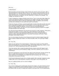
Page 4 July 2007Notes from the June 16, 2007 MeetingPresident Jim Sargent conducted our meeting, which was attended by about 20 people. He reminded us to get our reservationsin for the Convention. He informed us that we could sign up for a just-released new book “The Golden Age of RCA, 1919to 1929 - RADIOLA”. Several members signed up for this book, <strong>and</strong> we look forward to getting our copy!Program director Mike Grimes introduced our program on restoration. He used a Philco 60 to illustrate the process of evaluatingthe restoration challenges it might present. Following are observations about the set.The set was a little rough in appearance, needing some veneer <strong>and</strong> fretwork repairs on the front. The sides, top <strong>and</strong>bottom were in fair-to-good shape.The knobs were all missing. They can be found for this model.The chassis showed no signs of rust <strong>and</strong> would clean up quite well.The under-chassis was fairly clean, with some early repairs obvious (a digital camera can record the exact configurationof things before you start removing parts).The original electrolytic condensers were still in place <strong>and</strong> could be left installed for appearance’s sake or could beused to contain new, modern capacitors.The dial was OK, but the escutcheon was missing. A dial could be bought for this model, but is somewhat aninvestment considering the value of the radio. The escutcheon would be more difficult to find as a loose item (butpossible, with patience). A junk cabinet might be a more likely source.The wiring was OK, unlike some radios (e.g. later AK’s) that have crispy rubber on the wire that crumbles at thetouch.Mike brought up the possibility of combining another set of this same model, one having a good chassis or dial <strong>and</strong> the other agood cabinet. Of course it’s up to the individual how much time <strong>and</strong> money he wants to put into a radio restoration. If nostalgiais involved, or the joy of a challenge, it can be well worth it to the owner. After all, it may always remain in the restorer’scollection as a “keeper”. Mike said that as far as restoration goes, first of all, clean it up. This is easier with the tubesremoved (you may want to test them, anyway). A good blowing out with compressed air is good, if available (or a can of dustofffor computer keyboards). Then use cloth, brushes, toothpicks, Q-tips, sucker sticks, old toothbrushes or whatever to cleaneverything. Water is best, but don’t get it into the I.F. cans, coils or transformers. Mike says that one thing that works well isautomatic transmission fluid! (In the author’s experience, a radio that’s greasy must have been in a kitchen near the stove.Naphtha works well to remove grease – automatic transmission fluid probably does the same thing, but it might even leave avery thin protective film on the steel parts). He told us about a website that has a large number of radios that are catalogued<strong>and</strong> pictured as thumbnails. You can click on the thumbnails <strong>and</strong> see a larger picture. The site is – http://www.radioatticarchives.com.Mike then introduced member Mike McCarty, a returning presenter. (Mike talked to us about vacuum tubes in January).This time, he presented a program about the basic functional blocks of a typical radio <strong>and</strong> the process of restoration once youunderst<strong>and</strong> what those blocks do. His discussion focused on the most commonly encountered radios, the 5 or 6 tubesuperhet AC/DC radios. He emphasized safety – first of all don’t just plug it in! This is for the safety of the radio, as well as
Soundwaves Page 5yourself.Diagrams were used to illustrate the functional blocks, or stages, of a radio:1. A pre-selector (sometimes two in 6-tube sets) to select the frequency of the desired broadcast station - this consistsof the first, <strong>and</strong> possibly second, tuned circuits, including built-in antenna loop or ferrite-rod antenna. The localoscillator may be combined into this first stage, yielding the I.F. frequency signal that couples to the next stagethrough the 1 st I.F. transformer. The oscillator function relies on a separate coil assembly to create its tuned circuit.The pre-selector <strong>and</strong> oscillator frequencies are tuned by the ganged tuning capacitor (two or three gangs).2. An intermediate frequency (I.F.) stage that works at a fixed frequency - this stage amplifies the signal <strong>and</strong> narrowsthe frequency b<strong>and</strong> that will pass through to the following detector (This is what gives the superhet its good selectivity)- The frequency is generally about 455 kilohertz, but other frequencies are used, also, especially in older radios.This I.F. stage drives the 2 nd I.F. transformer, which couples the amplified intermediate frequency signal to the detector/filterstage.3. A detector/filter stage - this stage usually makes use of a multi-function tube (e.g. 12SQ7) that has diodes for convertingthe radio-frequency (R.F.) signal to an audio signal (the detection function) <strong>and</strong> also a triode section that serves toamplify the audio signal. A capacitor is used to filter out the R.F. component from the detected signal. The triodesection amplifies the detected signal to a higher level.4. A power amplifier stage- the audio signal from the triode is coupled to this amplifier tube (e.g. 50L6) via a capacitor(it’s very important to replace this capacitor!). This amplifier couples to the audio transducer – speaker or phones, viaan output transformer that converts the impedance to match the driven device <strong>and</strong> get the best power transfer from thetube to the device.5. A power supply stage - the radio is powered with basically two kinds of B+ voltage, a higher voltage for the poweroutput stage <strong>and</strong> a lower voltage for the amplifier/detector stages. “Filter” capacitors are used to smooth the otherwise-pulsatingD.C. for each supply. Any residual pulsation is called “ripple”. The higher voltage doesn’t need to beas ripple-free because the signal level is very high. The lower voltage needs to have very low ripple or it will result inhum at the power frequency. Typically, a resistor <strong>and</strong> second filter capacitor provide very smooth (low-ripple) power forthe lower voltage supply. The resistor drops both the voltage <strong>and</strong> the ripple. The capacitance values determine howlow the ripple levels are. If the electrolytic capacitors have dried out over time, their actual capacitance will be down<strong>and</strong> the radio will have that all-too-familiar hum.Mike described <strong>and</strong> demonstrated some techniques for troubleshooting a typical AC/DC set. Some people like to use avariac to “sneak up” the voltage while checking voltages in the radio. Mike prefers to use a test lamp setup that has beenused by many people in the past (the author’s father used this method for many years). Mike’s arrangement consists of abox with an outlet, a switch <strong>and</strong> a light bulb socket, powered with a cord having a polarized plug (one with a wide blade).From the “hot” side the lamp is connected in series with one of the outlet sockets <strong>and</strong> the switch is connected so as to shortout the lamp, when desired. This arrangement lets you limit the input current to the radio to safe levels using different sizes oflamp – 40 <strong>and</strong> 100 watt lamps generally suffice. An analysis showed that, with the 40 wall lamp, 16 watts is the maximumpower that can be delivered to the radio. You get useful clues from the brightness with which the lamps burn or glow. A radiowith problems, especially shorts or overloads, will make the lamp burn brightly <strong>and</strong> remain bright. A healthy radio will causethe lamp to start out fairly bright when the tubes are cold <strong>and</strong> then dim down to a dull glow after the radio warms up. Mikedemonstrated this <strong>and</strong> showed us that a healthy radio would actually play with the 40 watt lamp in series with it (The 100 wattlamp barely glows). Throwing the shorting switch makes it a little louder because the radio then gets full voltage.Mike demonstrated some voltmeter measurement techniques that are useful. First of all, DC voltage measurements of thetwo supply voltage mentioned earlier will reveal a lot about the radio. There are quite a few parts that can be eliminated aspossible trouble spots if these voltages are normal. They will be approximately 130 volts for the high <strong>and</strong> 90 volts for the low,depending on line voltage of course. If they aren’t, then a check of the filter capacitors is in order, or the rectifier tube. If thelow voltage is low, very often the culprit is the series resistor that feeds it from the higher voltage supply. Another useful tip isto measure the ripple voltages on the two supply voltages. This must be done with a meter that blocks any DC voltage fromaffecting the reading. One of Mike’s meters did but the other didn’t. (Note: Many old Simpson multi-meters have a jacklabeled “OUTPUT” that connects the test voltage through a capacitor that blocks the DC – when the capacitor is good, that is.You can use a good film-type capacitor of about 0.5 microfarad to do your own blocking). On his demonstration radio, Mikenoted ripple-voltage readings of 4 Vac on the higher voltage supply <strong>and</strong> 0.23 Vac on the lower. If these voltages are high, the
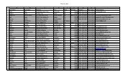
Page 6SoundWavesfilter capacitors need replacing, as they usually do.Mike stressed the issue of safety in working on hot-chassis radios. The often-discussed question was brought up about whythose radio power switches are wired to switch one side of the power cord directly to the chassis, instead of breaking thecircuit at the side feeding the filament string <strong>and</strong> rectifier. Theories from the audience included the idea that hum from theswitch might couple into the volume control, but the consensus is that it saved labor <strong>and</strong> material costs in a very competitivemanufacturing business. Mike said that he re-wires the radio power switch to place it in the “hot side” <strong>and</strong> uses line cordsthat have the polarizing feature (one wide blade). He also put forth the ideas of keeping one h<strong>and</strong> behind your back whenturning on or measuring, wearing rubber-soled shoes, using a rubber mat under the radio <strong>and</strong> keeping your meter right besidethe radio so you don’t lose sight of what your h<strong>and</strong>s are getting into. Another measure he takes involves the use of a simpleneon-lamp tester that is sometimes available at auto parts <strong>and</strong> hardware stores. This is a test lamp with two separate tippedleads that can be plugged into an outlet or touched to an object to see if there is power. If one test lead is connected to the“hot” side of the line cord or outlet (narrow slot), you can touch the other lead <strong>and</strong> the lamp will glow dimly from your bodycapacitance. This means you can tell if something is electrically “hot” or not. Mike uses this check to make sure thechassis is “cold” with the radio plugged in. He emphasized safety as though he has had a pretty good jolt at some time.Author’s note: I use a similar technique to Mike’s, using the same type of neon tester, which I have had for about 50 years.This works with the old style plugs that have two narrow blades. With the radio unplugged, I turn the radio ON (with thevolume control). From then on, I leave it on, until I have a special reason to turn it off, such as for checking the switch actionor volume control. Then I plug the radio in, briefly, with one lead of the neon tester already on the chassis <strong>and</strong> the other heldbetween two fingers. If the lamp glows, I reverse the plug, plug it back in briefly, <strong>and</strong> see that the lamp does not glow. If itdoesn’t, I reverse it, briefly, to confirm that it will glow (It’s always dangerous to rely on a “null” test). Then I put a piece oftape on the plug identifying the “safe” orientation. During the repair <strong>and</strong> troubleshooting, I always plug it in the “safe” way. Iwear rubber-soled shoes <strong>and</strong> make sure I have only one h<strong>and</strong> on anything when I turn the radio OFF. I’m sure an isolationtransformer reduces the risk of shock from the AC power line, but it won’t keep you from getting big jolts when you getacross parts of the radio, especially the early ones with more than 300 volts running around inside. For the most part,“respect” these voltages before they dem<strong>and</strong> respect!See you at the Repair Session July 21 st (in rubber-soled shoes).Bill McKeownDALLAS:WattersonDalbarAldingsonTalk-a-<strong>Radio</strong>DavisTexas Instruments (Regency)HOUSTON:Texan<strong>Radio</strong>s Manufactured in TexasWattersonSAN ANTONIO:SfericsAlamo<strong>Radio</strong>etteCLEBURNE:RangeaireATHENS, DALLAS, HOUSTON:Curtis MathesDalbar
July 2007 Page 7CAPACITOR MARKINGS AND UNITSCapacitor markings are not what they used to be. In vintage radio restoration most often our schematics refercapacitor (condensers) units in terms of microfarad or micro microfarad followed by the voltage. Modernmanufacturers use a different code, thanks to the microelectronics industry. If you run across three-digit numberon a capacitor that ends something like 203 or 203K(EIA code), it means 20,000 pF (picoFarads) or0.02uF(microFarads). The first-digit, <strong>and</strong> second-digit are the first significant figures. The third-digit is a multiplier.This numeric unit value is in picoFarads. This is the rule. Tolerance is often given after the numericvalue by letter code: F=+/-1%, G, H, J, K, M, Z, P. +/- 2, 3, 5, 10, 20, -20/+80, -0/+100, respectively. For instance,102K means 1,000 pF or .001 uF... or 104K means 100,000 pF or 0.1 uF. The “K” indicates a tolerance of +/- 10%.Often you need to know the units in microFarads. Since there are 1 X 10¹² pF/F <strong>and</strong> 1 X 10⁶ uF/F; then thereare 1 X 10⁶ pF/uF. Thus by example: 1 X 1<strong>05</strong> pF is equal to 1 X 10⁻¹ uF or 0.1 uF. By 1<strong>05</strong> pF/ 106 pF/uF = 10-1uF. Sometime nanofarads are specified(IEC code). Also, sometimes, nanofarads are useful with modern digitalcapacitor meters which have scales in nanometers. Since there are 1 X 10⁹ nF/F <strong>and</strong> 1 X 10⁶ uF/F, then thereare 1 X 10³ nF/uF. Examples of these values: read 100nF or 100n is equal to 0.1uF. Or 10nF or 10n indicates0.01uF. Simple huh.Try these:micro = 10-6; nano = 10-9; pico (also micromicro) = 10-12EIA is the most common from our suppliers.(EIA Code)ELECTRONIC INDUSTRY COMMISSIONcode: 333K 101J 104Kread: 33000pF 100pF 100,000pFread: .033uF .0001uF .1uFOf course, there is never just one st<strong>and</strong>ard. And occasionally the manufacturers mix severalst<strong>and</strong>ards together! The IEC interprets to nanofarads <strong>and</strong> is easy enough to figure out fromthese examples.(IEC Code)INTERNATIONAL ELECTROTECHNICAL COMMISSIONcode: 4n7 n22 100nread: 4.7 nF .22nF 100nFread: .0047uF .00022uF .1uFMike Grimes
VRPS CONVENTION 2007NOVEMBER 16,17,18 2007It’s time to make hotel reservations for the 2007 VRPS Convention. CallHampton Inn now to make reservations. State you are a member of VRPSor <strong>Vintage</strong> <strong>Radio</strong> <strong>and</strong> <strong>Phonograph</strong> <strong>Society</strong> toget the $79.00 room rate or if you want a suite,they are $102.00.THE HAMPTON INN & SUITESFOR RESERVATIONS CALL:1700 972-329-3100 RODEO DRIVERequest the VRPS Special Convention RateMESQUITE, TEXAS 75149Reservations Call:1-800-Hampton or (Local) 972-329-3100If you would like to make your reservation online:http://www.hilton.com/en/hp/groups/personalized/dalhshx_vrp/index.jhtmlTHE THEME FOR THISYEAR’S CONVENTION IS:TEXAS RADIOVRPS, INCPO BOX 165345IRVING, TEXAS 75016SOUNDWAVES IS PUBLISHED QUARTERLYBY THE VINTAGE RADIO AND PHONO-GRAPH SOCIETY, INC.OFFICERSJIM SARGENT, PRESIDENTCLEO CHERRYHOLMES, VICE PRESIDENTBOARD OF DIRECTORSSTAN BAKER, C.F. CRANDELL,RONALD DANIEL, BLAKE DIETZE,MIKE GRIMES, RANDY JAMES,ED JANSSEN, BILL MCKEOWN,GEORGE POTTER, GARY REEVESEDITORSSOUNDWAVES -- JEANNINE JAMESVRPS@SBCGLOBAL.NETWEBMASTER -- JOE SCHNEIDERWWW.VRPS.ORGTHE REPRODUCER -- GEORGE POTTERDEFOREST22@VERIZON.NET