An electron transparent proton detector for neutron decay studies
An electron transparent proton detector for neutron decay studies
An electron transparent proton detector for neutron decay studies

Create successful ePaper yourself
Turn your PDF publications into a flip-book with our unique Google optimized e-Paper software.
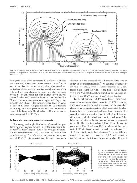
084904-7 Hoedl et al. J. Appl. Phys. 99, 084904 2006FIG. 10. A cutaway view of the equipotential surfaces near the focus elements as calculated by RELAX3D. Each equipotential surface represents 5% of thepotential of the <strong>proton</strong> foil typically −20 keV. The inner beam pipe, located immediately to the left of the <strong>proton</strong> <strong>detector</strong>, and the 200 V grid used <strong>for</strong> largerdetection foils, are .through the inside of the chamber to the surface of the biasedfoil, a vertically translatable silicon <strong>detector</strong> 25 mm 2 activearea to monitor the <strong>proton</strong> beam quality, a horizontal andvertical translation stage to scan the spatial response of thefoils, and electrode elements to focus secondary <strong>electron</strong>screated by the conversion foil into another silicon <strong>detector</strong>50 mm 2 active area located at the end of the chamber. The25 mm 2 <strong>detector</strong> was mounted on a copper cold finger connectedto a LN 2 dewar in the vacuum system. Brass collars atthe ends of the inner beam pipe minimized beam defocusingby ensuring that electric potential gradients were far from thecenter of the beam path. The chamber could achieve an ultimatepressure of 510 −7 Torr.C. Secondary <strong>electron</strong> focusing elementsThe energy and angle distribution of secondaries producedby <strong>proton</strong> passage through LiF or CsI is unknown. For<strong>electron</strong> 23 and ion 24 impact on Al, a cos weighted distributionhas been observed. X-ray impact on LiF gives a peaksecondary energy of 3 eV and a maximum secondary energyof 16 eV. 25 It is expected that the energy and angledistribution of the secondaries is independent of the type orenergy of the incident radiation. 26 We designed the electrodestructure to optimally focus secondaries produced in a 3 mmradius circle twice the radius of the final beam aperturewith a cos weighted angular distribution with energies between0.1 and 50 eV into the 50 mm 2 silicon <strong>detector</strong>.For a small diameter −20 kV biased foil, our design consistedof an extraction plate biased to −19 kV, which ensuredoptimal collection and prefocusing of the secondary<strong>electron</strong>s, an acceleration region, which accelerated the <strong>electron</strong>sto their full energy, and an Einzel lens, consisting of aground cylinder, a biased cylinder −15 kV, and then anotherground cylinder, which provided the final focus. A labeledcutaway view of the equipotential surfaces is presentedin Fig. 10. The trajectory path of 0.1 and 50 eV <strong>electron</strong>s ispresented in Fig. 11. A Monte Carlo simulation of the transportof 10 4 <strong>electron</strong>s calculated a collection efficiency of100% <strong>for</strong> both 0.1 and 50 eV <strong>electron</strong>s. For larger foils, weadded a 2 mm pitch grid biased at +200 V with respect tothe foil between the foil and the extraction plate. This gridFIG. 11. The trajectory of 100 secondary<strong>electron</strong>s emitted from the <strong>proton</strong>foil at 0.1 and 50 eV. Note that theactive area of the silicon <strong>detector</strong> wasbetween ±0.4 cm from the beam centerand along the beam axis at 28 cm.These simulations indicate the electrodestructure had a collection efficiencyof 100%.Downloaded 07 Jul 2006 to 152.14.73.48. Redistribution subject to AIP license or copyright, see http://jap.aip.org/jap/copyright.jsp