Valve Terminal System, Series HF04 - Coeva
Valve Terminal System, Series HF04 - Coeva
Valve Terminal System, Series HF04 - Coeva

You also want an ePaper? Increase the reach of your titles
YUMPU automatically turns print PDFs into web optimized ePapers that Google loves.
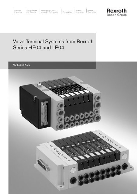
<strong>Valve</strong> <strong>Terminal</strong> <strong>System</strong>s from Rexroth<strong>Series</strong> <strong>HF04</strong> and LP04Technical Data
<strong>Valve</strong> <strong>Terminal</strong> <strong>System</strong>, <strong>Series</strong> <strong>HF04</strong>ProductsVersion 11: Sub-D connectionVersion 33: AS-i, B-Design,<strong>HF04</strong> with ASI 8DI/8DO-AUXPowerSee page 2 See page 4 See page 6Version 34: AS-i, B-Design,<strong>HF04</strong> with ASI 4DI/4DO-AUXPowerVersion 35: AS-i, B-Design,<strong>HF04</strong> with ASI 4DO-AUX PowerVersion 54: Profibus DP, B-DesignSee page 8 See page 10 See page 12Version 64: Profibus DP with8DI Modul, B-Design1
<strong>Valve</strong> <strong>Terminal</strong> <strong>System</strong>, <strong>Series</strong> <strong>HF04</strong>Version 11: Sub-D connectionTechnical DataTypeModularWorking pressure range, internal pilot control 3,0–8 bar (44–116 psi)Working pressure range, external pilot control Vacuum to 10 bar (145 psi)Min. admissible control pressure3,0 bar (44 psi)Ambient temperature range –5 °C to +50 °CDegree of protection according toEN 60 529/IEC 529IP 65 when assembledMedium5 µm filtered oil-free compressed air or40 µm filtered and oiled compressed airMedium temperature range 0 °C to +50 °CMaterialPlastic, polyamide(double-subplates and plug box)Aluminium (endplates)Nominal flow Qn400 Nl/minPneumatic connection 2 and 4Push-in connection, 6 mm dia.Stages of expansion1 to 6 double-subplates(1 to 24 valve solenoids)Rated voltage solenoid Un 24 V DC (–10 % / +10 %)Power consumption/solenoid0,35 W incl. LED and protective circuitOperating mode according to VDE 0580 Continuous operation (S1)Application AreaSuitable for most applications.Easy and fast mounting.Screw connection via through-holes (6,5x8,5 mm) or DIN rail DIN EN 50 022, 35x15.Fixture for DIN rail: see Accessories.Delivery range– Completely mounted and tested.– <strong>Valve</strong>s with LED and protected wiring.– Expansion stages: 1 to 6 double-subplates (1 to 12 valves, 1 to 24 valve solenoids).– Pilot air supply: internal or external.2
<strong>Valve</strong> <strong>Terminal</strong> <strong>System</strong>, <strong>Series</strong> <strong>HF04</strong>Version 11: Sub-D connection1 = Plug-in connection, pipe ∅ 8 mm2 and 4 = Plug-in connection, pipe ∅ 6 mm3 and 5 = Plug-in connection, pipe ∅ 10 mmR = restricted pilot air exhaust, plug-in connection, pipe ∅ 6 mmX = external pilot control, plug-in connection, pipe ∅ 6 mm, connection X closed with local pilot control1, 3 and 5 = screw connection M7 (supply plate)n 1 2 3 4 5 6A [mm] 60,6 84,2 107,8 131,4 155 178,6B [mm] 46,1 69,7 93,3 116,9 140,5 164,1n = Number of double-subplate position3
<strong>Valve</strong> <strong>Terminal</strong> <strong>System</strong>, <strong>Series</strong> <strong>HF04</strong>Version 33: AS-i, B-Design, <strong>HF04</strong> with ASI 8DI/8DO-AUX PowerTechnical DataDegree of protection according toEN 60 529/IEC 529Ambient temperature rangeIP 65 when assembled0° C to +50° C (32 °F to +122 °F)AS-i busI/O code 7ID code / ID2 codeF / ERated voltageaccording to AS-i specifcations 26,5 - 31,6 VPower consumption100 mAwith total output for sensorsmax. 200 mA (short-circuit proof)Rated current per valve solenoid30 mALoad supply 24 V DC externalRated voltage 24 V DC (-10% / +10%)Protective min. voltage (PELV) according to IEC 60364-4-41Residual ripple 0,5 %Rated current per valve solenoid30 mAElectromagnetic compatibilityInterference radiation EN 50295Interference irradiation EN 50295You can find the allocation schemes for individual products in the manuals or contact yournearest Bosch Rexroth sales office.Application AreaThis AS-i bus module comply with the AS-i specification V2.11 Rev. 1 (Jan. 31, 2001).AS-Interface module (as spare part or for retrofitting of a <strong>HF04</strong> valve unit, Sub-D)Module Manual Code No.Module for max. 8 coils and 8 inputs (8DI/8DO-AUX) R 499 050 017 R 412 003 486Incl. 2 tie rod and seal kitAccessories electronics (to be ordered separately)Accessories Cable length [m] Code No.Connection cable, straight, with selfsecuring coupling nut, M 8x1, 3-pins 2 894 620 360 2Connection cable, straight, with selfsecuring coupling nut, M 8x1, 3-pins 5 894 620 361 2Connection cable, straight, with selfsecuring coupling nut, M 8x1, 3-pins 10 894 620 362 2Protection cap M 8x1 (delivery unit: 25 pcs) – R 412 003 493AS-i cable socket (1 piece) incl. Label – 1 824 484 064Addressing cable – on requestEndplate for Bus module (incl. seal kit and mounting screws) – R 412 003 4904
<strong>Valve</strong> <strong>Terminal</strong> <strong>System</strong>, <strong>Series</strong> <strong>HF04</strong>Version 33: AS-i, B-Design, <strong>HF04</strong> with ASI 8DI/8DO-AUX Power<strong>Valve</strong> terminal system <strong>HF04</strong> with AS-i, ASI 8DI/8DO-AUXn 1 2 3 4A [mm] 138,6 162,2 185,8 209,4B [mm] 124,1 147,7 171,3 194,9n = Number of double-subplate position5
<strong>Valve</strong> <strong>Terminal</strong> <strong>System</strong>, <strong>Series</strong> <strong>HF04</strong>Version 34: AS-i, B-Design, <strong>HF04</strong> with ASI 4DI/4DO-AUX PowerTechnical DataDegree of protection according toEN 60 529/IEC 529Ambient temperature rangeIP 65 when assembled0° C to +50° C (32 °F to +122 °F)AS-i busI/O code 7ID code / ID2 codeF / ERated voltageaccording to AS-i specifcations 26,5 - 31,6 VPower consumption50 mAwith total output for sensorsmax. 200 mA (short-circuit proof)Rated current per valve solenoid30 mALoad supply 24 V DC externalRated voltage 24 V DC (–10% / +10%)Protective min. voltage (PELV) according to IEC 60364-4-41Residual ripple 0,5 %Rated current per valve solenoid30 mAElectromagnetic compatibilityInterference radiation EN 50295Interference irradiation EN 50295You can find the allocation schemes for individual products in the manuals or contact yournearest Bosch Rexroth sales office.Application AreaThis AS-i bus module comply with the AS-i specification V2.11 Rev. 1 (Jan. 31, 2001).AS-Interface module (as spare part or for retrofitting of a <strong>HF04</strong> valve unit, Sub-D)Module Manual Code No.Module for max. 4 coils and 4 inputs (4DI/4DO-AUX) R 499 050 017 R 412 003 487Incl. 2 tie rod and seal kitAccessories electronics (to be ordered separately)Accessories Cable length [m] Code No.Connection cable, straight, with selfsecuring coupling nut, M 8x1, 3-pins 2 894 620 360 2Connection cable, straight, with selfsecuring coupling nut, M 8x1, 3-pins 5 894 620 361 2Connection cable, straight, with selfsecuring coupling nut, M 8x1, 3-pins 10 894 620 362 2Protection cap M 8x1 (delivery unit: 25 pcs) – R 412 003 493AS-i cable socket (1 piece) incl. Label – 1 824 484 064Addressing cable – on requestEndplate for Bus module (incl. seal kit and mounting screws) – R 412 003 4906
<strong>Valve</strong> <strong>Terminal</strong> <strong>System</strong>, <strong>Series</strong> <strong>HF04</strong>Version 34: AS-i, B-Design, <strong>HF04</strong> with ASI 4DI/4DO-AUX Power<strong>Valve</strong> terminal system <strong>HF04</strong> with AS-i, ASI 4DI/4DO-AUXn 1 2A [mm] 138,6 162,2B [mm] 124,1 147,7n = Number of double-subplate position7
<strong>Valve</strong> <strong>Terminal</strong> <strong>System</strong>, <strong>Series</strong> <strong>HF04</strong>Version 35: AS-i, B-Design, <strong>HF04</strong> with ASI 4DO-AUX PowerTechnical DataDegree of protection according toEN 60 529/IEC 529Ambient temperature rangeIP 65 when assembled0° C to +50° C (32 °F to +122 °F)AS-i busI/O code 8ID code / ID2 codeF / ERated voltageaccording to AS-i specifcations 26,5 - 31,6 VPower consumption50 mALoad supply 24 V DC externalRated voltage 24 V DC (–10% / +10%)Protective min. voltage (PELV) according to IEC 60364-4-41Residual ripple 0,5 %Rated current per valve solenoid30 mAElectromagnetic compatibilityInterference radiation EN 50295Interference irradiation EN 50295You can find the allocation schemes for individual products in the manuals or contact yournearest Bosch Rexroth sales office.Application AreaThis AS-i bus module comply with the AS-i specification V2.11 Rev. 1 (Jan. 31, 2001).AS-Interface module (as spare part or for retrofitting of a <strong>HF04</strong> valve unit, Sub-D)Module Manual Code No.Module for max. 4 coils (AS-i 4DO-AUX) R 499 050 017 R 412 003 488Incl. mounting screw and seal kitAccessories electronics (to be ordered separately)AccessoriesCode No.AS-i cable socket (1 piece) incl. Label 1 824 484 064Addressing cableon request8
<strong>Valve</strong> <strong>Terminal</strong> <strong>System</strong>, <strong>Series</strong> <strong>HF04</strong>Version 35: AS-i, B-Design, <strong>HF04</strong> with ASI 4DO-AUX Power<strong>Valve</strong> terminal system <strong>HF04</strong> with AS-i, AS-i 4DO-AUXn 1 2A [mm] 81,6 105,2B [mm] 46,1 69,7n = Number of double-subplate position9
<strong>Valve</strong> <strong>Terminal</strong> <strong>System</strong>, <strong>Series</strong> <strong>HF04</strong>Version 54: Profibus DP, B-DesignTechnical DataDegree of protection according toEN 60 529/IEC 529Ambient temperature rangeIP 65 when assembled0 °C to +50 °C (32 °F to +122 °F)Electrical Data (BUSdirect)Operating voltage valves 24V DC +10% / –10%Operating voltage electronics 24V DC +20% / –15%Current consumption electronics200 mACurrent supply for valves0,9 AExternal fuseFuse valvesFuse electronics with input voltage supplyRun-up timeafter connection of supply voltage2 A, quick-acting3,15 A, quick-acting< 5 sElectromagnetic compatibilityInterference radiation EN 61000-6-4 (August 2002)Interference irradiation DIN EN 61131-2 (April 2001)Programmable controllersPart 2: Equipment requirements and tests EN 61131-2You can find the allocation schemes for individual products in the manuals or contact yournearest Bosch Rexroth sales office.Accessories electronics (to be ordered separately)AccessoriesCode No.Data plug Profibus: data input plug, M 12x1, 5-pins, straight, B-coded, ∅ 6-8 mm, (X71, BUS IN) 894 105 404 4Data plug Profibus: data output plug, M 12x1, 5-pins, straight, B-coded (X72, BUS OUT) 894 105 405 4Data plug Profibus: data input plug, M 12x1, 5-pins, angled, B-coded (X71, BUS IN) 1 824 484 027Data plug Profibus: data output plug, M 12x1, 5-pins, angled, B-coded (X72, BUS OUT) 1 824 484 026Plug-in connector for supply voltage, M12x1 socket coupling, 4-pin for cable ∅ 4-8 mm,894 105 432 4A-coded, 180° (X10, POWER)Plug-in connector for supply voltage, M12x1 socket coupling, 4-pin for cable ∅ 4-8 mm,894 105 442 4A-coded, 90° (X10, POWER)M 12x1 Protective cap 1 823 312 001Endplate for Bus module (incl. seal kit and mounting screws) R 412 003 490BUSdirect modules (as spare part or for retrofitting of a <strong>HF04</strong> valve unit, Sub-D)Protocol Manual Code no.PROFIBUS DP R 499 050 016 R 412 003 484Incl. 2 tie rod and seal kit10
<strong>Valve</strong> <strong>Terminal</strong> <strong>System</strong>, <strong>Series</strong> <strong>HF04</strong>Version 54: Profibus DP, B-DesignX71, (BUS IN), M12x1X72, (BUS OUT), M12x1X10, (POWER), M12x1n 1 2 3 4 5 6A [mm] 138,6 162,2 185,8 209,4 233 256,6B [mm] 124,1 147,7 171,3 194,9 218,5 242,1n = Number of double-subplate position11
<strong>Valve</strong> <strong>Terminal</strong> <strong>System</strong>, <strong>Series</strong> <strong>HF04</strong>Version 64: Profibus DP with 8DI Module, B-DesignTechnical Data (pneumatics)Degree of protection according toEN 60 529/IEC 529Ambient temperature rangeIP 65 when assembled0 °C to +50 °C (32 °F to +122 °F)InputInputs according to EN 61131-2 8 digital inputs, type 3(Two-wire proximity switch with idle current ofmax. 2,5 mA connectable)Input delay 0 - 13 msInput delay 1 - 03 msType of input connectorRound connector M8x1Electromagnetic compatibilityInterference radiation EN 61000-6-4Interference irradiation DIN EN 61131-2, EN 61000-6-2To be used max. 3 input modules.You can find the allocation schemes for individual products in the manuals or contact yournearest Bosch Rexroth sales office.Accessories electronics (to be ordered separately)Accessories Cable length [m] Code No.Connection cable, straight, with selfsecuring coupling nut, M 8x1, 3-pins 2 894 620 360 2Connection cable, straight, with selfsecuring coupling nut, M 8x1, 3-pins 5 894 620 361 2Connection cable, straight, with selfsecuring coupling nut, M 8x1, 3-pins 10 894 620 362 2Protection cap M 8x1 (delivery unit: 25 pcs) – R 412 003 4938DI modules (as spare part or for retrofitting of a <strong>HF04</strong> valve unit with Profibus-DP)Incl. 2 tie rod and seal kitManualCode no.R 499 050 016 R 412 003 48912
<strong>Valve</strong> <strong>Terminal</strong> <strong>System</strong>, <strong>Series</strong> <strong>HF04</strong>Version 64: Profibus DP with 8DI Module, B-Designn 1 2 3 4 5 6A + (60 x m) [mm] 138,6 162,2 185,8 209,4 233 256,6B + (60 x m) [mm] 124,1 147,7 171,3 194,9 218,5 242,1n = number of double-subplates positionm = number of input modules, max. 3 input modules13
<strong>Valve</strong> <strong>Terminal</strong> <strong>System</strong>, <strong>Series</strong> LP04ProductsVersion 11: Sub-D connectionon the sideVersion 12: Sub-D connectionon the topSee page 15 See page 17 See page 19Version 64: BusDirect withProfibus DPVersion 68: BusDirect withDeviceNetVersion 80: DDL, without inputsSee page 21 See page 23 See page 25Version 81: DDL, with 10 inputsAccessories<strong>Valve</strong>sAccessories and other parts(to be ordered separately)See page 27 See page 2914
<strong>Valve</strong> <strong>Terminal</strong> <strong>System</strong>, <strong>Series</strong> LP04Version 11: Sub-D connection on the sideTechnical DataTypeModularWorking pressure range, internal pilot control 3,0–8 bar (44–116 psi)Working pressure range, external pilot control Vacuum to 10 bar (145 psi)Min. admissible control pressure3,0 bar (44 psi)Ambient temperature range –5 °C to +50 °CDegree of protection according toEN 60 529/IEC 529IP 65 when assembledMedium5 µm filtered oil-free compressed air or40 µm filtered and oiled compressed airMedium temperature range0 °C to +50 °C (32 °F to +122 °F)MaterialPlastic, polyamideNominal flow Qn300 Nl/minPneumatic connection port 2 and 4 Push-in connection, 6 mm or 4 mm, 1/4" or 1/8"tube dia.Number of valves per VTS 4 to 16 in steps of 2Number of valve solenoids 4 to 24Rated voltage solenoid Un 24 V DC (–10 % / +10 %)Power consumption/solenoid0,35 W incl. LED and protective circuitOperating mode according to VDE 0580 Continuous operation (S1)Application AreaSuitable for space limited applications.Easy and fast mounting.Low weight, short response times.Screw connection via through-holes (4,5x5,5 mm)Delivery range– Completely mounted and tested.– VTS with 4 to 16 valves.– Expansion stages: 1 double sub-base.– <strong>Valve</strong>s with LED and protected wiring.– Pilot air supply: Internal or external.– Integrated silencers.AccessoriesAccessory Cable length [m] Code No.25 pins Sub-D connector with cable 3 049 385 980 725 pins Sub-D connector with cable 10 049 384 570 5Sub-D connector with cable, dynamic laying 10 894 620 390 215
<strong>Valve</strong> <strong>Terminal</strong> <strong>System</strong>, <strong>Series</strong> LP04Version 11: Sub-D connection on the sideA = 75,8 + number of sub-bases x 11,8B = 61 + number of sub-bases x 11,8C = Connection port 1: 8 mm, 10 mm or 3/8"D = Connection port 2 and 4: 4 mm, 6 mm, 1/8" or 1/4"E = Port 3 and 5: plugged (integrated silencer)F = Option: External pilot air supply or internal pilot air supplyG = 62,1 + number of sub-bases x 11,8 (internal pilot air supply)H = 69,1 + number of sub-bases x 11,8 (external pilot air supply)J = Connection port X (external pilot air supply): 4 mmK = Integrated silencer*) Dimension for 5/3-way valve only16
<strong>Valve</strong> <strong>Terminal</strong> <strong>System</strong>, <strong>Series</strong> LP04Version 12: Sub-D connection on the topTechnical DataTypeModularWorking pressure range, internal pilot control 3,0–8 bar (44–116 psi)Working pressure range, external pilot control Vacuum to 10 bar (145 psi)Min. admissible control pressure3,0 bar (44 psi)Ambient temperature range –5 °C to +50 °CDegree of protection according toEN 60 529/IEC 529IP 65 when assembledMedium5 µm filtered oil-free compressed air or40 µm filtered and oiled compressed airMedium temperature range0 °C to +50 °C (32 °F to +122 °F)MaterialPlastic, polyamideNominal flow Qn300 Nl/minPneumatic connection port 2 and 4 Push-in connection, 6 mm or 4 mm, 1/4" or 1/8"tube dia.Number of valves per VTS 4 to 16 in steps of 2Number of valve solenoids 4 to 24Rated voltage solenoid Un 24 V DC (–10 % / +10 %)Power consumption/solenoid0,35 W incl. LED and protective circuitOperating mode according to VDE 0580 Continuous operation (S1)Application AreaSuitable for space limited applications.Easy and fast mounting.Low weight, short response times.Screw connection via through-holes (4,5x5,5 mm).Delivery range– Completely mounted and tested.– VTS with 4 to 16 valves.– Expansion stages: 1 double sub-base.– <strong>Valve</strong>s with LED and protected wiring.– Pilot air supply: Internal or external.– Integrated silencers.17
<strong>Valve</strong> <strong>Terminal</strong> <strong>System</strong>, <strong>Series</strong> LP04Version 12: Sub-D connection on the topA = 71 + number of sub-bases x 11,8B = 61 + number of sub-bases x 11,8D = Connection port 2 and 4: 4 mm, 6 mm, 1/8" or 1/4"E = Port 3 and 5: plugged (integrated silencer)F = Option: External pilot air supply or internal pilot air supplyG = 62,1 + number of sub-bases x 11,8 (internal pilot air supply)H = 69,1 + number of sub-bases x 11,8 (external pilot air supply)J = Connection port X (external pilot air supply): 4 mmK = Integrated silencer*) Dimension for 5/3-way valve only18
<strong>Valve</strong> <strong>Terminal</strong> <strong>System</strong>, <strong>Series</strong> LP04Version 64: BusDirect with Profibus DPTechnical DataTypeWorking pressure range, internal pilot controlWorking pressure range, external pilot controlMin. admissible control pressureAmbient temperature rangeDegree of protection according toEN 60 529/IEC 529MediumMedium temperature rangeMaterialModular3,0–8 bar (44–116 psi)Vacuum to 10 bar (145 psi)3,0 bar (44 psi)0 °C to +50 °C (32 °F to +122 °F)IP 65 when assembled5 µm filtered oil-free compressed air or40 µm filtered and oiled compressed air0 °C to +50 °C (32 °F to +122 °F)Plastic, polyamideNominal flow Qn300 Nl/minPneumatic connection port 2 and 4 Push-in connection, 6 mm or 4 mm, 1/4" or 1/8"tube dia.Number of valves per VTS 4 to 16 in steps of 2Number of valve solenoids 4 to 32Rated voltage solenoid Un 24 V DC (–10 % / +10 %)Power consumption/solenoid0,35 W incl. LED and protective circuitOperating mode according to VDE 0580 Continuous operation (S1)Electrical Data (BusDirect)Operating voltage valves 24 V DC +10% / –10%Operating voltage electronics 24 V DC +20% / –20%Current consumption electronics0.2 ACurrent supply for valves0.9 AExternal fuseFuse valvesFuse electronics with input voltage supplyRun-up timeafter connection of supply voltage2 A, quick-acting1 A, quick-acting< 5 sProgrammable controllersPart 2: Equipment requirements and tests EN 61010-1You can find the allocation schemes for individual products in the manuals or contact yournearest Bosch Rexroth sales office.Application AreaSuitable for space limited applications.Easy and fast mounting.Low weight, short response times.Screw connection via through-holes (4,5x5,5 mm).Delivery range– Completely mounted and tested.– VTS with 4 to 16 valves.– Expansion stages: 1 double sub-base.– <strong>Valve</strong>s with LED and protected wiring.– Pilot air supply: Internal or external.– Integrated silencers.Accessories electronics (to be ordered separately)AccessoriesCode No.Data plug Profibus: data input plug, M 12x1, 5-pins, straight, B-coded, ∅ 6-8 mm, (X71, BUS IN) 894 105 404 4Data plug Profibus: data output plug, M 12x1, 5-pins, straight, B-coded (X72, BUS OUT) 894 105 405 4Data plug Profibus: data input plug, M 12x1, 5-pins, angled, B-coded (X71, BUS IN) 1 824 484 027Data plug Profibus: data output plug, M 12x1, 5-pins, angled, B-coded (X72, BUS OUT) 1 824 484 026Plug-in connector for supply voltage, M12x1 socket coupling, 4-pin for cable ∅ 4-8 mm,894 105 432 4A-coded, 180° (X10, POWER)Plug-in connector for supply voltage, M12x1 socket coupling, 4-pin for cable ∅ 4-8 mm,894 105 442 4A-coded, 90° (X10, POWER)M 12x1 Protective cap 1 823 312 001BusDirect modulesProtocolManualPROFIBUS DP R 402 000 61619
<strong>Valve</strong> <strong>Terminal</strong> <strong>System</strong>, <strong>Series</strong> LP04Version 64: BusDirect with Profibus DPVersion 64: BusDirect with Profibus DPA = 83,5 + number of sub-bases x 11,8B = 61 + number of sub-bases x 11,8C = Connection port 1: 8 mm, 10 mm or 3/8"D = Connection port 2 and 4: 4 mm, 6 mm, 1/8" or 1/4"E = Port 3 and 5: plugged (integrated silencer)F = Option: External pilot air supply or internal pilot air supplyG = 62,1 + number of sub-bases x 11,8 (internal pilot air supply)H = 69,1 + number of sub-bases x 11,8 (external pilot air supply)J = Connection port X (external pilot air supply): 4 mmK = Integrated silencer*) Dimension for 5/3-way valve only20
<strong>Valve</strong> <strong>Terminal</strong> <strong>System</strong>, <strong>Series</strong> LP04Version 68: BusDirect with DeviceNetTechnical DataTypeWorking pressure range, internal pilot controlWorking pressure range, external pilot controlMin. admissible control pressureAmbient temperature rangeDegree of protection according toEN 60 529/IEC 529MediumMedium temperature rangeMaterialModular3,0–8 bar (44–116 psi)Vacuum to 10 bar (145 psi)3,0 bar (44 psi)0 °C to +50 °C (32 °F to +122 °F)IP 65 when assembled5 µm filtered oil-free compressed air or40 µm filtered and oiled compressed air0 °C to +50 °C (32 °F to +122 °F)Plastic, polyamideNominal flow Qn300 Nl/minPneumatic connection port 2 and 4 Push-in connection, 6 mm or 4 mm, 1/4" or 1/8"tube dia.Number of valves per VTS 4 to 16 in steps of 2Number of valve solenoids 4 to 32Rated voltage solenoid Un 24 V DC (–10 % / +10 %)Power consumption/solenoid0,35 W incl. LED and protective circuitOperating mode according to VDE 0580 Continuous operation (S1)Electrical Data (BusDirect)Operating voltage valves 24 V DC +10% / –10%Operating voltage electronics 24 V DC +20% / –20%Current consumption electronics0.2 ACurrent supply for valves0.9 AExternal fuseFuse valvesFuse electronics with input voltage supplyRun-up timeafter connection of supply voltageApplication AreaSuitable for space limited applications.Easy and fast mounting.Low weight, short response times.Screw connection via through-holes (4,5x5,5 mm)2 A, quick-acting1 A, quick-acting< 5 sDelivery range– Completely mounted and tested.– VTS with 4 to 16 valves.– Expansion stages: 1 double sub-base.– <strong>Valve</strong>s with LED and protected wiring.– Pilot air supply: Internal or external.– Integrated silencers.Accessories electronics (to be ordered separately)AccessoriesCode No.Data plug DeviceNet: data input plug, M 12x1, 5-pins, straight, B-coded, ∅ 6-8 mm, (X71, BUS IN) 440 723 002 0Plug-in connector for supply voltage, M12x1 socket coupling, 4-pin for cable ∅ 4-8 mm,894 105 432 4A-coded, 180° (X10, POWER)Plug-in connector for supply voltage, M12x1 socket coupling, 4-pin for cable ∅ 4-8 mm,894 105 442 4A-coded, 90° (X10, POWER)M 12x1 Protective cap 1 823 312 001BusDirect modulesProtocolManualDeviceNet R 402 000 61721
<strong>Valve</strong> <strong>Terminal</strong> <strong>System</strong>, <strong>Series</strong> LP04Version 68: BusDirect with DeviceNetVersion 68: BusDirect with DeviceNetA = 75,8 + number of sub-bases x 11,8B = 61 + number of sub-bases x 11,8C = Connection port 1: 8 mm, 10 mm or 3/8"D = Connection port 2 and 4: 4 mm, 6 mm, 1/8" or 1/4"E = Port 3 and 5: plugged (integrated silencer)F = Option: External pilot air supply or internal pilot air supplyG = 62,1 + number of sub-bases x 11,8 (internal pilot air supply)H = 69,1 + number of sub-bases x 11,8 (external pilot air supply)J = Connection port X (external pilot air supply): 4 mmK = Integrated silencer*) Dimension for 5/3-way valve only22
<strong>Valve</strong> <strong>Terminal</strong> <strong>System</strong>, <strong>Series</strong> LP04Version 80: DDL, without inputsTechnical DataWorking pressure range, internal pilot controlWorking pressure range, external pilot controlMin. admissible control pressureAmbient temperature rangeDegree of protection according toEN 60 529/IEC 529MediumMedium temperature rangeMaterial3,0–8 bar (44–116 psi)Vacuum to 10 bar (145 psi)3,0 bar (44 psi)0 °C to +50 °C (32 °F to +122 °F)IP 65 when assembled5 µm filtered oil-free compressed air or40 µm filtered and oiled compressed air0 °C to +50 °C (32 °F to +122 °F)Plastic, polyamideNominal flow Qn300 Nl/minPneumatic connection port 2 and 4 Push-in connection, 6 mm or 4 mm, 1/4" or 1/8"tube dia.Number of valves per VTS 4, 8, 12 or 16Number of valve solenoids 4 to 32Rated voltage solenoid Un 24 V DC (–10 % / +10 %)Power consumption/solenoid0,35 W incl. LED and protective circuitOperating mode according to VDE 0580 Continuous operation (S1)Electrical Data (BusDirect)Operating voltage valvesOperating voltage electronicsCurrent consumption electronicsCurrent supply for valvesRun-up timeafter connection of supply voltage24 V DC via DDL24 V DC via DDL0.05 A0.9 A< 5 sApplication AreaSuitable for space limited applications.Easy and fast mounting.Low weight, short response times.Screw connection via through-holes (4,5x5,5 mm).Delivery range– Completely mounted and tested.– VTS with 4, 8, 12 or 16 valves.– <strong>Valve</strong>s with LED and protected wiring.– Pilot air supply: Internal or external.– Integrated silencers.Accessories electronics (to be ordered separately)AccessoriesCode No.Plug-in connector for supply voltage, M12x1 socket coupling, 4-pin for cable ∅ 4-8 mm,894 105 432 4A-coded, 180° (X10, POWER)Plug-in connector for supply voltage, M12x1 socket coupling, 4-pin for cable ∅ 4-8 mm,894 105 442 4A-coded, 90° (X10, POWER)M 12x1 Protective cap 1 823 312 001DDL connector, with cable 0.3 m 894 605 466 2DDL connector, with cable 0.5 m 894 605 467 2DDL connector, with cable 1 m 894 605 468 2DDL connector, with cable 2 m 894 605 469 2DDL connector, with cable 5 m 894 605 470 2DDL connector, with cable 10 m 894 605 471 2DDL ManualProtocolManualDDL R 402 000 48323
<strong>Valve</strong> <strong>Terminal</strong> <strong>System</strong>, <strong>Series</strong> LP04Version 81: DDL, with 10 inputsA = 175,5 + number of sub-bases x 11,8B = 61 + number of sub-bases x 11,8C = Connection port 1: 8 mm, 10 mm or 3/8"D = Connection port 2 and 4: 4 mm, 6 mm, 1/8" or 1/4"E = Port 3 and 5: plugged (integrated silencer)F = Option: External pilot air supply or internal pilot air supplyG = 166,6 + number of sub-bases x 11,8 (internal pilot air supply)H = 173,6 + number of sub-bases x 11,8 (external pilot air supply)J = Connection port X (external pilot air supply) : 4 mmK = Integrated silencer*) Dimension for 5/3-way valve only26
<strong>Valve</strong> <strong>Terminal</strong> <strong>System</strong>s, <strong>Series</strong> <strong>HF04</strong> and LP042 x 3/2, 5/2 and 5/3 directional-control valve for <strong>Series</strong> <strong>HF04</strong> and LP04<strong>Valve</strong>sTypeSpool valve, elastic sealing, non over-lappingWorking pressure range, local pilot control 3,0–8 bar (44–116 psi)Working pressure range, external pilot control Vacuum to 10 bar (145 psi)min. admissible control pressure3,0 bar (44 psi)Nominal flow rate Qnat 6 bar (87 psi), ∆p = 1 bar (15 psi)400 Nl/minAmbient temperature range –5 °C to +50 °CMedium5 µm filtered oil-free compressed air or40 µm filtered and oiled compressed airMedium temperature range 0 °C to +50 °CMaterials (body)Plastic, polyamide (PA and PPS)Operating voltagessee tablePower consumption per coilsee table(incl. LED and protective circuit)Protection in mounted position IP 65 to IEC 529 (DIN VDE 0470)Operating mode according to VDE 0580 continuous operation (S1)Application AreaThe valve is non over-lapping. Easy and fast mounting.Control pressure diagram only for 2 x 3/2 directional-control valve, external pilot controlCode No.RatedvoltagePowerconsumptionper coilCode<strong>Valve</strong>Code no.Turn withdetentCode no.TurnI 0 820 062 101 0 820 062 10224 V DC 0,35 W J 0 820 062 201 0 820 062 202G 0 820 062 301 0 820 062 302A 0 820 062 051 0 820 062 05224 V DC 0,35 W B 0 820 062 001 0 820 062 002C 0 820 062 501 0 820 062 50224 V DC 0,35 W D 0 820 062 601 0 820 062 6025/3 center position exhaust can be done using 2 x 3/2 NC - NC (NC = normally closed)5/3 center position supply with air can be done using 2 x 3/2 NO - NO (NO = normally open)27
<strong>Valve</strong> <strong>Terminal</strong> <strong>System</strong>s, <strong>Series</strong> <strong>HF04</strong> and LP042 x 3/2, 5/2 and 5/3 directional-control valve for <strong>Series</strong> <strong>HF04</strong> and LP042 x 3/2 and 5/2 directional-control valve 5/3 directional-control valve28
<strong>Valve</strong> <strong>Terminal</strong> <strong>System</strong>s, <strong>Series</strong> <strong>HF04</strong> and LP04Accessories and other partsAccessories and other parts (to be ordered separately)<strong>HF04</strong> LP04 Accessory Code no. CommentsX X Dummy plate, including 1x seal kit, 2x mounting screws 1 825 700 104X X Supply plate, including 1x seal kit, 2x mounting screws 1 821 039 039X X Sub-D connector, with cable 3 m 049 385 980 7X X Sub-D connector, with cable 10 m 049 384 570 5 Version 11X X Sub-D connector, with cable 10 m, dynamic laying 894 620 390 2XExtension kit, double sub-base without circuit board.For extension from 4 to 6 valve positions.R 402 000 485XExtension kit, double sub-base with circuit board.266 020 109 0For extension of versions 11 and 12, single solenoid valvesXExtension kit, double sub-base with circuit board.266 020 009 0For extension of versions 11 and 12, double solenoid valvesXExtension kit, double sub-base with circuit board.266 020 309 0For extension of versions 64 and 68X Extension screws, 3 pcs R 402 000 484X 4 mm push-in fitting, including locking device 049 387 281 8X 6 mm push-in fitting, including locking device 049 387 290 7Extension screwsand fittingsmust be ordered separatelyX 1/8" push-in fitting, including locking device 049 387 300 4X 1/4" push-in fitting, including locking device R 402 000 489X Module with port X for external pilot air supply R 402 000 490 See dimensional drawingsX Module for internal pilot air supply R 402 000 491Pos. FX Separator: Separation between two double subplates, channel 1 R 412 003 402(delivery unit: 10 pcs).X Separator: Separation between two double subplates, channel 3 and 5 R 412 000 998(delivery unit: 10 pcs).X Separator: Separation between two valve positions, channel 1, 3 and 5 R 412 003 404X (delivery unit: 5 pcs for channel 1, 10 pcs for channel 3 and 5).X Subplate extension (1x subplate, 2x tie rod extensions, 1x seal kit). 1 827 010 708X Mounting kit for rail DIN EN 50 022, 35x15. 1 827 010 709X Blanking plug for connection 2 and 4, dia. 6 mm (delivery unit: 50 pcs). 1 823 391 248X Blanking plug for connection 1, 8 mm dia. (delivery unit: 25 pcs). 1 823 105 007XBlanking plugs for connection 3 and 5, 10 mm dia.1 823 391 441(delivery unit: 10 pcs).XSilencer for restricted pilot air exhaust, connection R, dia. 6 mm R 412 000 591(delivery unit: 5 pcs).XSilencer for air exhaust, connection 3 and 5, dia. 10 mmR 412 000 593(delivery unit: 5 pcs).X Silencer for supply plate, connection 3 and 5, dia. M7, sintered bronze. 814 000 070 0X Gasket for double subplate On request29
Bosch Rexroth AGPneumaticsUlmer Straße 4DE-30880 LaatzenTel.: +49 (0)511-21 36-0Fax: +49 (0)511-21 36-269sales-pneumatics@boschrexroth.dewww.boschrexroth.com/pneumaticsYour contact:© Bosch Rexroth Teknik AB,Stockholm, SwedenComponents described are subjectto alteration without prior noticeR402000469 EN / 2003-12II