
You also want an ePaper? Increase the reach of your titles
YUMPU automatically turns print PDFs into web optimized ePapers that Google loves.
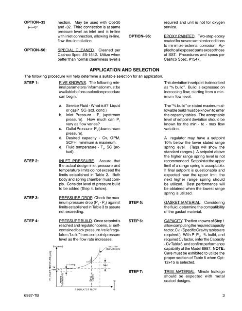
OPTION–33(cont.):OPTION–56:nec tion. May be used with Opt-30and -32. Third connection is at samepres sure level as inlet and is in-linewith inlet connection, allowing in-line,fl ow-thru in stal la tion.SPECIAL CLEANED. Cleaned perCashco Spec. #S-1542. Utilize whenbetter than normal clean li ness level isOPTION–95:required and unit is not for oxygenservice.EPOXY PAINTED. Two-step epoxycoated for severe ambient conditionsto minimize external corrosion. Appliedto all exposed parts except thoseof SST. Pro ce dures and specs perCashco Spec. #1547.STEP 1:APPLICATION AND SE LEC TIONThe following procedure will help determine a suitable selection for an application.FIVE KNOWNS. The following minimal parameters / information must beavailable before a se lec tion pro ce durecan begin:This deviation in setpoint is de scribedas “% build”. Build is expressed onincreasing fl ow, starting from a minimum fl ow level.STEP 2:STEP 3:a. Service Flu id - What is it? Liquidor gas? SG (std. cond.)b. Inlet Pres sure - P 1(up streampres sure). How much can P 1vary as fl ow var ies?c. Outlet Pres sure - P 2(down streampressure).d. Desired ca pac i ty - Cv, GPM,SCFH; min i mum & max i mum.e. Fluid tem per a ture - T 1, SG (actual).INLET PRESSURE. Assure thatthe actual design inlet pressure andtem per a ture limits do not exceed thelim its established in Table 2. Bothbody and spring chamber must comply.Consider level of pressure buildto be added (Step 4. below).PRESSURE DROP. Check the maximum pressure drop (P 1- P 2) againstlimits established in Table 3 to as surenot exceeding.STEP 5:The “% build” or stated maximum allowablebuild must be known to enterthe capacity tables. The ac cept ablelevel of setpoint de vi a tion should beknown for the min - to - max fl owvariation.A regulator may have a setpoint10% below the lower stated rangespring level. (Tags will show thestandard ranges.) A setpoint abovethe higher range spring level is notrec om mend ed. Setpoint at the upperlimit of a range spring is acceptable.If fi nal setpoint is ques tion able andex pect ed near the upper limit, thenext higher range spring shouldbe uti lized. Best performance willbe ob tained when the lowest rangespring is utilized.GASKET MATERIAL: Consideringthe fl uid, determine the compatibilityof the gasket material.STEP 4:PRESSURE BUILD. Once setpoint isreached and regulator opens, all selfcontainedback pressure / relief regulators“build” from a setpoint pres surelevel as the fl ow rate increases.STEP 6:CAPACITY. The five knowns of Step 1allow computing the re quired ca pac i tyfactor, Cv. (Specific Gravity tables arerequired.) With P 1,P 2, % build, andrequired Cv factor, enter the Capacity- Cv Table 5, and con firm performancecapability of the Model 6987. NOTE:Care must be exhibited to utilize theproper section of Table 5 when Opt-12+15 is se lect ed.STEP 7:TRIM MATERIAL. Minute leakageshould be expected with metalseat ed designs.6987-TB 3