

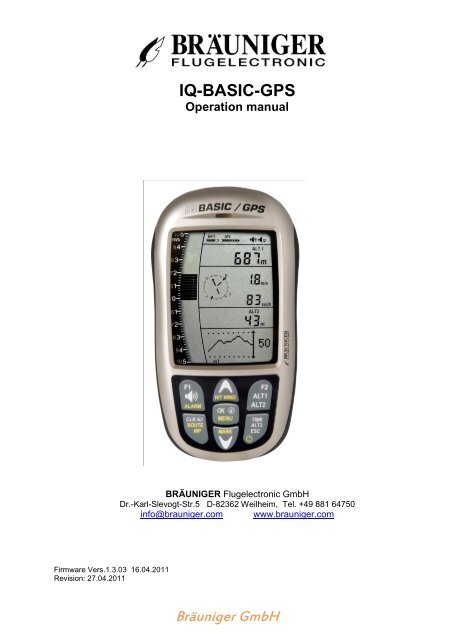
IQ-BASIC-GPS Operation manual - Bräuniger GmbH
IQ-BASIC-GPS Operation manual - Bräuniger GmbH
IQ-BASIC-GPS Operation manual - Bräuniger GmbH

Create successful ePaper yourself
Turn your PDF publications into a flip-book with our unique Google optimized e-Paper software.
Firmware Vers.1.3.03 16.04.2011<br />
Revision: 27.04.2011<br />
<strong>IQ</strong>-<strong>BASIC</strong>-<strong>GPS</strong><br />
<strong>Operation</strong> <strong>manual</strong><br />
BRÄUNIGER Flugelectronic <strong>GmbH</strong><br />
Dr.-Karl-Slevogt-Str.5 D-82362 Weilheim, Tel. +49 881 64750<br />
info@brauniger.com www.brauniger.com<br />
<strong>Bräuniger</strong> <strong>GmbH</strong>
Index<br />
<strong>Operation</strong> Manual <strong>IQ</strong>-<strong>BASIC</strong>-<strong>GPS</strong> 1<br />
1 <strong>Operation</strong> ............................................................................................................................... 3<br />
1.1 ...... Instrument overview ....................................................................................................................... 3<br />
1.2 ...... <strong>IQ</strong>-<strong>BASIC</strong>-<strong>GPS</strong> Switch - on and - off .............................................................................................. 4<br />
1.2.1 Instrument switch-on ................................................................................................................ 4<br />
1.2.2 Instrument switch-off / stop flight recording .............................................................................. 4<br />
1.3 ...... Keypad ............................................................................................................................................. 5<br />
1.4 ...... <strong>Operation</strong> philosophy ..................................................................................................................... 5<br />
1.4.1 Function related keys F1 and F2 .............................................................................................. 5<br />
1.5 ...... Display screen ................................................................................................................................. 6<br />
1.5.1.1 Graphics / data fields display ............................................................................................... 6<br />
1.6 ...... The setting menus .......................................................................................................................... 7<br />
1.6.1 Menu Overview ......................................................................................................................... 8<br />
2 Functions ............................................................................................................................... 9<br />
2.1 ...... Altimeter and atmospheric pressure ............................................................................................ 9<br />
2.1.1 Altimeter Alt1, absolute altitude ................................................................................................ 9<br />
2.1.1.1 Manual setting of altimeter Alt1 ............................................................................................ 9<br />
2.1.2 Altimeter display Alt2 .............................................................................................................. 10<br />
2.1.2.1 Manual setting of altimeter Alt2 (A2 relative mode) ........................................................... 10<br />
2.1.2.2 Altimeter display Alt2 - definition ........................................................................................ 10<br />
2.1.3 Altimeter display Alt3 (differential altimeter) ........................................................................... 10<br />
2.2 ...... Variometer functions .................................................................................................................... 11<br />
2.2.1 Analogue-Vario ....................................................................................................................... 11<br />
2.2.2 Digital-Vario (average value-Vario) ...................................................................................... 11<br />
2.2.2.1 Average value-Vario (integrating Vario) ............................................................................. 11<br />
2.2.3 Variometer Acoustics and volume level (Sound) ................................................................... 11<br />
2.2.3.1 Audio level .......................................................................................................................... 11<br />
2.2.4 Menu Settings Variometer ...................................................................................................... 12<br />
2.2.4.1 Digital-Vario Integrator ....................................................................................................... 12<br />
2.2.4.2 Threshold value last thermal .............................................................................................. 12<br />
2.2.4.3 Basic filter (Turbulence filter) ............................................................................................. 12<br />
2.2.5 Variometer - Acoustic settings ................................................................................................ 12<br />
2.2.6 Variometer – climb acoustic ................................................................................................... 13<br />
2.2.6.1 Climb acoustic threshold .................................................................................................... 13<br />
2.2.6.2 Basic frequency .................................................................................................................. 13<br />
2.2.6.3 Variometer climb acoustic � Frequency change .............................................................. 13<br />
2.2.6.4 Variometer Climb acoustic � Pitch change / increase of tone interval per m/s ............... 13<br />
2.2.7 Pre-Thermal Acoustic Threshold ............................................................................................ 14<br />
2.2.8 Variometer – sink acoustic ..................................................................................................... 14<br />
2.2.8.1 SinktoneF = Basic Tone pitch Variometer Sink ................................................................. 14<br />
Sinktone threshold ............................................................................................................................... 14<br />
Sink Alarm threshold ........................................................................................................................... 14<br />
2.3 ...... Speed .............................................................................................................................................. 15<br />
2.3.1 Wind vane sensor ................................................................................................................... 15<br />
2.3.2 Stallalarm ................................................................................................................................ 15<br />
2.3.3 Speed without speed sensor .................................................................................................. 15<br />
2.4 ...... Time of day and Date .................................................................................................................... 16<br />
2.4.1 Flight duration (flight time) ..................................................................................................... 16<br />
2.5 ...... Temperature .................................................................................................................................. 16<br />
3 Navigation ............................................................................................................................ 16<br />
3.1 ...... Assessment of <strong>GPS</strong> reception quality ........................................................................................ 17<br />
3.2 ...... Compass and flight direction....................................................................................................... 17<br />
3.2.1 Track and Bearing .................................................................................................................. 18<br />
3.3 ...... Waypoints and Coordinates......................................................................................................... 18<br />
3.3.1 Display of actual coordinates ................................................................................................. 19<br />
3.3.2 Memorising the actual position ............................................................................................... 19<br />
3.3.3 Waypoints, alter, delete or adding .......................................................................................... 19<br />
3.3.3.1 Edit Waypoints ................................................................................................................... 19<br />
OK key = modify WP characteristics ................................................................................................... 19<br />
3.3.3.2 Keypad functions in Menu Edit .......................................................................................... 20<br />
3.3.3.3 Delete all WP ..................................................................................................................... 20<br />
3.3.4 Goto–Function ........................................................................................................................ 20<br />
3.4 ...... Routes ............................................................................................................................................ 21
<strong>Operation</strong> Manual <strong>IQ</strong>-<strong>BASIC</strong>-<strong>GPS</strong> 2<br />
3.4.1 Creating a Route .................................................................................................................... 21<br />
3.4.1.1 Route >Edit ........................................................................................................................ 21<br />
3.4.1.2 > Delete alle WP of the Route ............................................................................................ 22<br />
3.4.2 Flying Routes .......................................................................................................................... 22<br />
3.4.2.1 Starting a normal Route ..................................................................................................... 22<br />
3.4.2.2 Competition Route - Definition and start ............................................................................ 22<br />
3.4.3 Competition - Start.................................................................................................................. 23<br />
3.4.3.1 EXIT / ENTER Cylinder ..................................................................................................... 23<br />
3.4.3.2 Comp. Route Start signals ................................................................................................. 23<br />
3.4.3.3 Competition Route – Data display for task Exit Cyl. .......................................................... 24<br />
3.4.3.4 Competition Route - Data display for task Enter Cyl. ........................................................ 24<br />
3.4.3.5 Approaching a WP Cylinder ............................................................................................... 24<br />
3.4.3.6 Waypoints - skip / backspace............................................................................................. 24<br />
3.5 ...... Flight optimisation ........................................................................................................................ 25<br />
3.5.1 Groundspeed (speed over ground) ........................................................................................ 25<br />
3.5.2 Wind direction and Wind strength .......................................................................................... 25<br />
3.5.3 Glide ratio (= L/D ratio) .......................................................................................................... 25<br />
3.5.4 Glide ratio (= L/D ratio) .......................................................................................................... 25<br />
3.5.5 Relocating thermals ................................................................................................................ 26<br />
4 Flight-Memory and Flight-Analysis .................................................................................... 26<br />
4.1.1 Flight logbook and Flight Analysis .......................................................................................... 26<br />
5 Data transfer ........................................................................................................................ 27<br />
5.1 ...... Data exchange via PC ................................................................................................................... 27<br />
5.1.1 Flight instrument settings ....................................................................................................... 28<br />
5.1.2 Waypoints and Routes ........................................................................................................... 28<br />
6 Transmitting new Software-(Firmware) to the <strong>IQ</strong>-<strong>BASIC</strong>-<strong>GPS</strong> .......................................... 28<br />
7 Miscellaneous ...................................................................................................................... 29<br />
8 Batteries ............................................................................................................................... 29<br />
8.1 ...... Batterie charge state ..................................................................................................................... 29<br />
8.2 ...... Battery replacement ...................................................................................................................... 29<br />
9 Additional Information ........................................................................................................ 30<br />
9.1 ...... Altimeter ......................................................................................................................................... 30<br />
9.1.1 How does an altimeter work? ................................................................................................. 30<br />
9.2 ...... Navigation ...................................................................................................................................... 31<br />
9.2.1 Reception quality of <strong>GPS</strong> ....................................................................................................... 31<br />
9.2.2 Accuracy of <strong>GPS</strong> altitude ....................................................................................................... 31<br />
9.3 ...... Flight Memory and IGC File.......................................................................................................... 32<br />
9.3.1 Evidence of flights – Security against manipulation ............................................................... 32<br />
10 Maintenance ..................................................................................................................... 33<br />
10.1.1 Exposure to water................................................................................................................... 33<br />
11 Warranty ........................................................................................................................... 33<br />
12 Technical Data ................................................................................................................. 34<br />
13 Approval / Conformity ..................................................................................................... 34<br />
<strong>Bräuniger</strong> <strong>GmbH</strong>
<strong>Operation</strong><br />
1.1 Instrument overview<br />
15<br />
14<br />
16<br />
13<br />
<strong>Operation</strong> Manual <strong>IQ</strong>-<strong>BASIC</strong>-<strong>GPS</strong> 3<br />
17<br />
12<br />
11 10<br />
1 ON / OFF key<br />
2 Page indicator<br />
3 Graphics and data display<br />
4 Differential altimeter / time / flight time /QNH<br />
5 Speed<br />
6 USB PC-interface<br />
7 Digital Vario display<br />
8 Altimeter display ALT1 / ALT2<br />
9 Audio Acoustics indicators<br />
10 <strong>GPS</strong> Satellite Indicator<br />
11 Loud speaker<br />
12 Battery capacity<br />
13 Compass rose<br />
14 Analogue Vario display<br />
15 Jack for speed sensor<br />
16 Keypad<br />
17 Safety cord<br />
<strong>Bräuniger</strong> <strong>GmbH</strong><br />
9<br />
1<br />
6<br />
8<br />
2<br />
7<br />
3<br />
ON / OFF key<br />
5<br />
4
<strong>Operation</strong> Manual <strong>IQ</strong>-<strong>BASIC</strong>-<strong>GPS</strong> 4<br />
1.2 <strong>IQ</strong>-<strong>BASIC</strong>-<strong>GPS</strong> Switch - on and - off<br />
1.2.1 Instrument switch-on<br />
Switch-On ?<br />
Press OK !<br />
Test Batt.<br />
2.86 V<br />
The instrument is switched-on by pressing the On/Off key.<br />
To prevent unintentional switch-on, it needs to be acknowledged<br />
upon display prompt: Switch-On?<br />
by pressing the OK key.<br />
Following acknowledgement the display will shift for approx.<br />
15 sec. to the switch-on display screen with following<br />
information:<br />
- Battery state, serial number, pilot’s name, instrument type and<br />
- Software (Firmware) Version.<br />
After switch-on the normal flight screen shall appear with flashing altitude data display. The<br />
device needs approx. two minutes to calculate the precise 3D-<strong>GPS</strong> position. As soon as<br />
the <strong>GPS</strong> receives stabilised altitude data, the pressure altimeter is automatically adjusted,<br />
the altitude data display stops flashing and the symbol <strong>GPS</strong> appears over the <strong>GPS</strong> data display.<br />
1.2.2 Instrument switch-off / stop flight recording<br />
Switch-off ?<br />
Press OK !<br />
End recording?<br />
Switch-off ?<br />
Press OK !<br />
For switch-off the On/Off key needs to<br />
be pressed until the question: Switchoff?<br />
Press OK is prompted on the<br />
screen.<br />
Again, to prevent unintentional switch-off, also this action needs to<br />
be acknowledged by pressing the OK key!<br />
1. If no flight recording has been programmed, the instrument is<br />
immediately switched-off following acknowledgement by OK.<br />
2. Following an active flight recording the read-out screen<br />
Flight – Analysis is displayed during 60sec. before switch-off.<br />
If you want to quit the flight analysis display early, press shortly the<br />
Off-key, the instrument will then be switched-off immediately.<br />
3. Automatic switch-off: the flight analysis appears<br />
automatically after landing and shall be displayed for about<br />
60sec. Without key stroke the <strong>IQ</strong>-<strong>BASIC</strong>-<strong>GPS</strong> is switched-off<br />
automatically.<br />
4. Automatic switch-off at non-use<br />
If the device does not detect a keystroke or flight related<br />
parameters during 30 minutes, it will be switched-off<br />
automatically.<br />
<strong>Bräuniger</strong> <strong>GmbH</strong>
1.3 Keypad<br />
Function related key F1<br />
Audio Volume<br />
Alarm Settings<br />
Diff. Altimeter 3 reset to 0<br />
Route or Waypoint<br />
activate / deactivate<br />
1.4 <strong>Operation</strong> philosophy<br />
<strong>Operation</strong> Manual <strong>IQ</strong>-<strong>BASIC</strong>-<strong>GPS</strong> 5<br />
Shift graphics display<br />
in setting mode up / down<br />
The <strong>IQ</strong>-<strong>BASIC</strong>-<strong>GPS</strong> instrument is very easy to handle and intuitive. Just try it a few times, and you<br />
will discover that one can get along very rapidly with the simple menu structure. However, please<br />
note some essential instructions regarding the various functions.<br />
- White key lettering: display screen shifts such as for ex. ALT1 / ALT2, Vario- acoustic settings,<br />
F1 / F2 key commands and the (i) information retrieval, can be performed speedily during the flight<br />
by short pressure on the key.<br />
- Yellow key lettering: by long pressure of 3 sec. important functions may be called up directly<br />
during the flight and may also be edited. The selected function is switched-off after approx.<br />
8 seconds in case of non-use!<br />
- Main menu: all instrument settings, but also Waypoints-, Routes- and flight memory, can be<br />
set prior to the flight via the Main menu (MENU key). It is possible to select within the menu<br />
submenus by use of the up-/down keys and to enter adjustments. The main menu is quitted<br />
automatically at 30 seconds after the last entry.<br />
Tip: all instrument settings of the Main menu can be set comfortably by use of the freebie PC-<br />
Software Flychart on the PC and be transferred via USB-interface onto the instrument.<br />
1.4.1 Function related keys F1 and F2<br />
during flight: insert marker into flight<br />
recording / Memorise position as Waypoint<br />
Both keys F1 and F2 alter their setting possibility according to selected function or readout<br />
screen. The meaning of the related key is indicated on the display screen.<br />
Example: in setmode ALT 1 the function of F1 is "accept <strong>GPS</strong> altitude" and the function of F2<br />
is to set the altimeter to „FL 1013mB pressure“!<br />
<strong>Bräuniger</strong> <strong>GmbH</strong><br />
Altitude display<br />
Shift ALT1 / ALT2<br />
Settings altimeter<br />
Acknowledgement key OK<br />
Main Menu<br />
i Info key: display of current<br />
coordinates or of Information<br />
Display shift - time / altitude 3<br />
On/Off key<br />
Escape key<br />
Function related key F2
1.5 Display screen<br />
Vario Unit<br />
Direction North<br />
Compass rose<br />
Direction to WP<br />
Analogue Vario<br />
Wind direction<br />
1.5.1.1 Graphics / data fields display<br />
<strong>Operation</strong> Manual <strong>IQ</strong>-<strong>BASIC</strong>-<strong>GPS</strong> 6<br />
In normal flight mode it is possible to shift the graph page by short pressure on the keys<br />
▲UP or ▼DOWN. The number of the current page is indicated on the display bottom.<br />
Sequence: ALT, VAR, 1, 2, 3, 4, 5. After switch-on the page of altitude graphics (ALT)<br />
is always displayed.<br />
ALT<br />
VAR<br />
Battery charge state<br />
50<br />
1<br />
0<br />
-1<br />
3-D <strong>GPS</strong> Fix<br />
Altimeter Graphics display<br />
In this graph is illustrated the course of altitude during the past<br />
36 seconds. If the altitude difference is more than 50m, the scale<br />
is automatically adapted. The height scale is displayed on the<br />
right side. (50 /100m)<br />
Variometer Graphics display<br />
In this graph page is illustrated the course of Variometer during<br />
the past 36 seconds. The scale is automatically adapted to the<br />
flight track. The scale values are displayed on the right side.<br />
<strong>Bräuniger</strong> <strong>GmbH</strong><br />
<strong>GPS</strong> number of Satellites<br />
Rec<br />
Altimeter<br />
ALT1 / ALT2<br />
Current page dot display<br />
Flight recording<br />
Acoustic Volume<br />
Sink acoustics<br />
Digital Vario<br />
with Integrator<br />
Last thermal<br />
Speed display<br />
Different. altimeter<br />
Time / Flight time<br />
QNH<br />
Graphics- and Data field –<br />
display screen
<strong>Operation</strong> Manual <strong>IQ</strong>-<strong>BASIC</strong>-<strong>GPS</strong> 7<br />
Track 256 Wind data- display 1 (1)<br />
W-Direct. 095 Actual track (0-360°)<br />
Wind direction (0 – 360°)<br />
Wind 12<br />
Wind speed<br />
1<br />
Tegelberg Navigation data- 1 display (2)<br />
Bearing 270<br />
Active Waypoint from Route, GoTo or last Thermal<br />
Bearing in degree<br />
Dist. 26 Distance<br />
2<br />
Track 256<br />
Bearing 270<br />
Req.L/D 9,6<br />
3<br />
Navigation data- display (3)<br />
Actual track<br />
Bearing<br />
Req. Glide ratio to reach the active Waypoint<br />
GND 36 WP Approach data- 1 display (4)<br />
Speed over Ground<br />
L/D-GND 8,2<br />
Glide ratio Ground<br />
Req.L/D -:- 9,6 Req. Glide ratio to reach the next Waypoint (Goal)<br />
)� -01:05:36<br />
v-req. 9<br />
Competition Route data – display (5)*<br />
Position to Cylinder 1 / +/- Start time<br />
Required speed to reach the Start cylinder at Start time 0:00<br />
Dist.Cy 9,328<br />
5<br />
Distance to Cylinder<br />
*This data field can only be selected with active Route!<br />
1.6 The setting menus<br />
4<br />
- 1<br />
- 1<br />
- 1<br />
- 1<br />
- 1<br />
By long pressure on the MENU key access is given to the Menu setting mode. Using the keys ▼<br />
and ▲ one of the Menu items (flashing line) is selected and pressing the OK key gives access to<br />
the corresponding menu or submenu.<br />
Flashing values can be modified by use of<br />
the ▲UP or ▼DOWN key. By pressing the<br />
OK key the setting is memorised. Using the<br />
ESC (escape) key operates the return to the<br />
normal flight display screen. If there is no<br />
keystroke effected during 30sec., the<br />
instrument returns automatically to the flight<br />
display screen.<br />
<strong>Bräuniger</strong> <strong>GmbH</strong>
1.6.1 Menu Overview<br />
<strong>Operation</strong> Manual <strong>IQ</strong>-<strong>BASIC</strong>-<strong>GPS</strong> 8<br />
Menue Display <strong>IQ</strong>-<strong>BASIC</strong> Range Page<br />
Flight memory Flight Mem 26<br />
>Flights (flight memory) Flights 26<br />
> Recording interval Scanrate 1 – 60 Sec. 26<br />
> Recording mode Scan mode Auto / Manual 26<br />
> Delete all flights delete 26<br />
Waypoints Waypts 18<br />
>Edit / Insert / Delete 1 WP Edit 200 WP 19<br />
>Delete all WP Delete all 19<br />
Route Route 21<br />
>Edit Edit Route 50 WP 21<br />
>Delete Del Route 21<br />
Variometer Vario Set 11<br />
>Digital Vario Integrator Vario Dig 1 – 30 Sec. 11<br />
>Basic filter Vario Thr 0 – 1 – 2 – 3<br />
>Threshold Thermal Exit Vario Filt 0,5 – 3,0 m/s 12<br />
Variometer Climb Acoustics Climb Aud 13<br />
>Climb threshold Climb Thr 0 – 20 cm/s 13<br />
>Basic frequency Climb Freq 600 – 1400 Hz 13<br />
>Frequency modification Freq Adj 0 – 1 – 2 – 3 – 4 13<br />
>Pitch modification Pitch Adj 0 – 1 – 2 – 3 – 4 – 5 13<br />
>Pitch Mode (lin. / exp.) Pitch Mode lin. / exp. 13<br />
>Pre-Thermal Threshold PThermLim 0 up to -1,0m/s 13<br />
Variometer Sink Acoustics Sink Aud 14<br />
>Sink threshold Sink Thr - 0.1 … 20.0 m/s 14<br />
>Basic frequency Sink Freq 300 – 1000 Hz 14<br />
>Sink Alarm Sink Alarm - 0.1 … 99.9 m/s 14<br />
Speed Speed 15<br />
>Stall Alarm Stall Alarm 0 – 10 … 99 km/h 15<br />
>Impeller Corr. Spd Corr 50…100 … 150 15<br />
Pilot Pilot 29<br />
>Pilot’s name Pilot Name 16 Zeichen 29<br />
>Type of aircraft AC Type 16 Zeichen 29<br />
>Aircraftt ID AC ID 16 Zeichen 28<br />
Instrument settings Inst Set<br />
>Time zone Time Zone +/- 13 Std. 29<br />
>Alt 2 Mode Batt Type Absolut / Relativ / <strong>GPS</strong> / Inv.A1 9<br />
>Units Units<br />
Altimeter Alt Unit m / ft.<br />
Speed Spd Unit kmh / mph / kt<br />
Temperature Temp Unit °C / °F<br />
Pressure Press Unit hPa / inHg<br />
Vario Vario Unit m/s / ft.Min*100<br />
Time format Time Form 12h / 24h<br />
Coordinates format Coord Form dd.ddddd / dd’mm.mm / dd’mm’ss<br />
Factory settings Fact Set<br />
>Sensor Nullpunkt Press Corr +/- 10.0 hPa<br />
> Set Instr. to default Rst default Set Instr. To Original State<br />
> Instr. / PCB No. Device No Info SN No. / PCB No.<br />
> Sensor adjustment Intern Set Code<br />
<strong>Bräuniger</strong> <strong>GmbH</strong>
2 Functions<br />
<strong>Operation</strong> Manual <strong>IQ</strong>-<strong>BASIC</strong>-<strong>GPS</strong> 9<br />
2.1 Altimeter and atmospheric pressure<br />
The <strong>IQ</strong>-<strong>BASIC</strong>-<strong>GPS</strong> provides 3 altitude displays and 1 QNH pressure indicator.<br />
ALT1 The altimeter absolute altitude shows the altitude over sea level. (meter „m“ or feet „ft“)<br />
ALT2 alternatively: - <strong>GPS</strong> altitude<br />
- Flightlevel pressure altimeter display in relation to 1013hPa<br />
- meter or feet inverse to ALT1 (Absolute A1)<br />
- Relativ Altimeter<br />
ALT3 The altimeter relative altitude shows the altitude towards a reference point.<br />
QNH Actual air pressure at sea level in relation to ALT1<br />
2.1.1 Altimeter Alt1, absolute altitude<br />
Shifting between display screens Alt1 and Alt2 is effected by shortly<br />
pressing the Alt1/Alt2 key.<br />
Altitude display Alt1 indicates always the absolute pressure altitude above sea level.<br />
After switch-on the altimeter ALT1 is automatically adjusted to <strong>GPS</strong> altitude by the instrument.<br />
After switch-on the display is flashing until the <strong>GPS</strong>-receiver has calculated a precise<br />
altitude for adjustment.<br />
Units m / ft. - re-setting: see Menu � Instrument settings � Units<br />
2.1.1.1 Manual setting of altimeter Alt1<br />
Set mode A1 of altimeter is called-up by long pressure on the<br />
ALT1 key. The possible settings are shown in the information<br />
field.<br />
By brief pressure on one arrow key the readout value can be<br />
adjusted meter by meter. Under keystroke the display shall be<br />
changed automatically until the key is released.<br />
Due to this adjustment the QNH display is also altered.<br />
Adopt <strong>GPS</strong> altitude with F2 key<br />
By brief pressure on the F2 key it is possible to adopt the <strong>GPS</strong><br />
altitude. Please consider that the <strong>GPS</strong>-receiver does not always provide<br />
the reliable altitude value! In case of poor Satellite constellation or bad<br />
reception, altitude deviation of +/- 50 m will occur!<br />
Setting altitude to pressure standard 1013hPa with F1 key<br />
By brief pressure on the F1 key the altitude is set to 1013hPa (Flightlevel).<br />
Tip: If the user does not know the altitude of his present location, he may operate<br />
the QNH field and, using the arrow keys, by changing the altitude value until it matches<br />
the actual QNH as per weather forecast or indication issued by air traffic management.<br />
<strong>Bräuniger</strong> <strong>GmbH</strong>
2.1.2 Altimeter display Alt2<br />
<strong>Operation</strong> Manual <strong>IQ</strong>-<strong>BASIC</strong>-<strong>GPS</strong> 10<br />
Shifting between display screens Alt1 and Alt2 is performed by briefly<br />
pressing the key Alt1/Alt2.<br />
The following values can be displayed on the altimeter screen ALT 2:<br />
<strong>GPS</strong> Alt. = display of <strong>GPS</strong> altitude<br />
Flight-Level = Flightlevelaltitude in ft relatingto 1013 hPa e.g. display Fl 14 stands for being in<br />
Flight Level 1400 ft ( display in steps of 100 ft )<br />
ALT1 m/ft-Inv = display of altitude ALT1 inverse to unit of ALT1 in ft or m<br />
Relative = the relative altimeter displays altitude with reference to a point.<br />
Altitude setting of this point of reference can be set in A2 set mode at<br />
anytime.<br />
2.1.2.1 Manual setting of altimeter Alt2 (A2 relative mode)<br />
Prolonged pressure on the ALT2 key during ALT2-display activates the instrument into<br />
setting mode.<br />
By briefly pressing one arrow key the display indicator can be adjusted meter by meter.<br />
The displayed value is changed automatically as long as the key is pushed until it is<br />
released.<br />
Tip: the relative altimeter can be used for example for measuring the superelevation above<br />
landing site. For this purpose ALT2 will be reset to zero related to the landing site altitude.<br />
2.1.2.2 Altimeter display Alt2 - definition<br />
Altimeter A2 mode can be defined in the menu (Main Setup Menu � Instrument Settings �<br />
Alt2 mode).<br />
Tip: in altimeter display screen ALT2 altitude ALT1 can be selected in ft (inverse to unit ALT1<br />
in m). This information may be of importance when being in contact with the air traffic controller of<br />
Restricted Areas (CTR’s).<br />
2.1.3 Altimeter display Alt3 (differential altimeter)<br />
Altimeter Alt3 is in any case a differential altimeter. It indicates always the difference in regard<br />
to the altitude value on which it has been reset to zero for the last time. This function is often<br />
required to measure the elevation above the start site, or to detect easily during the flight in a<br />
weak thermal the height gain – or loss.<br />
Example: altitude ALT3 is set automatically to 0 m at start site, after take-off the altitude<br />
display Alt3 shall always indicate the altitude above start site.<br />
Reset altitude ALT3 to 0m<br />
By brief pressure on the CLR ALT3 key the altitude ALT3 may be reset to 0m at any time.<br />
<strong>Bräuniger</strong> <strong>GmbH</strong>
2.2 Variometer functions<br />
2.2.1 Analogue-Vario<br />
<strong>Operation</strong> Manual <strong>IQ</strong>-<strong>BASIC</strong>-<strong>GPS</strong> 11<br />
The most important indication for a non-motor driven<br />
aircraft is without any doubt the Variometer.<br />
It displays the vertical speed in meter/second and informs<br />
the pilot about the actual climb or sink rate.<br />
It is only possible for the pilot by using the Vario (and its<br />
accompanying acoustics) to determine the most efficient<br />
thermal climb, and in the opposite situation, to recognise<br />
when he is sinking too rapidly in downwind which he should<br />
leave at best speed.<br />
The scale of the analogue display is consistently 0,2 m/s over both scale ranges! (Flytec AG Patent!)<br />
The range of the first scale extends from 0 up to +/- 5m/s. Thereafter the scale display switches<br />
automatically to the second scale range which extends from 5 up to 10m/s. The second scale is<br />
afterwards displayed with a white bar on black field.<br />
2.2.2 Digital-Vario (average value-Vario)<br />
The Digital Vario has a scale of 10 cm/s and an extensive measuring range of up to +/- 100 m/s.<br />
It is therefore also appropriate to display and record even measuring flights up to the free fall.<br />
2.2.2.1 Average value-Vario (integrating Vario)<br />
The digital Vario display can be set under Main Setup Menu � Variometer� Digital as average<br />
value Vario (also designated as integrating Vario) with a time constant of 1 to 30s. The values are<br />
recalculated per second and indicate the average value of climb or sink rate within the adjusted time<br />
span. At gruff narrow hillside up-wind this helpful readout may be used to determine if a circle or aft<br />
flight would provide better climb values. Integration time should be selected more longer in accordance<br />
to the thermal’s roughness.<br />
Based upon practical experience, we recommend an average value of 5 - 10 seconds.<br />
2.2.3 Variometer Acoustics and volume level (Sound)<br />
In order to enable the pilot to follow the current climb- resp. sink rate without looking on the<br />
instrument, the Vario-Acoustics generate a tone sequence dependent on the value data.<br />
It varies in relation to climb- and sink rate in tone pitch, as well as for interval frequency<br />
(number of beep tones per second).<br />
The Vario-Acoustic corresponds always to the value of Analogue-Vario and is therefore<br />
reproducing the direct values, i.e not the average values being selected in the digital Vario<br />
readout screen.<br />
The Variometer Climb- and Sink Acoustics can be adapted with high flexibility on the <strong>IQ</strong>-<strong>BASIC</strong>-<strong>GPS</strong><br />
in manifold fields to one’s individual and personal requirements.<br />
2.2.3.1 Audio level<br />
By use of the key Audio level the sound volume of the built-in loud speaker is<br />
adjusted. Indeed five sound levels may be set, from soundless to maximum<br />
sound volume. The selected value is displayed with the Audio Symbol and is<br />
confirmed with a short beep or double-beep. The selectable sound levels are:<br />
0 - 25% - 50% - 75% - 100% - 0.<br />
<strong>Bräuniger</strong> <strong>GmbH</strong><br />
Vario 3.2 5,0 6.8m/s
<strong>Operation</strong> Manual <strong>IQ</strong>-<strong>BASIC</strong>-<strong>GPS</strong> 12<br />
Short pressure on the Audio Level-key shall increase the volume level each time<br />
by 25 %.<br />
2.2.4 Menu Settings Variometer<br />
Tip: By use of the PC Software Flychart Extras -> Flight instrument Options, all instrument<br />
characteristics can be set easily and comfortably.<br />
By use of the feature tone simulation the adjusted values can be checked easily!<br />
2.2.4.1 Digital-Vario Integrator<br />
Main Setup Menu � Variometer � Digital<br />
Setting of average value time constant from 1 – 30 seconds for the digital Variometer display.<br />
2.2.4.2 Threshold value last thermal<br />
Main Setup Menu � Variometer �<br />
Threshold for the display arrowhead of last thermal, the range can be set between 0,5 up to 3 m/s.<br />
The thermal arrowhead in the compass rose points to the direction, where the integrated Vario was<br />
the last time higher than this threshold value.<br />
2.2.4.3 Basic filter (Turbulence filter)<br />
Main Setup Menu � Variometer � Filter .<br />
The response characteristics of Variometer display and of climb- or sink acoustics can be adapted<br />
within a wide range in accordance to the pilot’s needs or the weather conditions.<br />
In order to simplify the settings, Flytec has defined 4 basic- resp. turbulence filters.<br />
Variometer - sensitivity / response characteristics<br />
Filter No.<br />
0 weak filtering for very calm air in Winter<br />
1 Default normal filtering for enjoyment thermal with light turbulence<br />
2 high filtering thermal with turbulence<br />
3 very high turbulence filtering for very rough and strong thermal<br />
2.2.5 Variometer - Acoustic settings<br />
The climb tone is a frequency modulated beep tone whose pitch and beep tone sequence rises<br />
rhythmically at increasing climb rate. The pulse/pause ratio is 1:1.<br />
Following settings are possible under Main Setup Menu � Variometer Climb Acoustic and<br />
Variometer Sink Acoustic:<br />
Climb Acoustic settings:<br />
Climb threshold: = climb acoustic threshold<br />
Basic frequency = basic tone pitch Vario climb<br />
Frequency change = increase of tone pitch<br />
(frequency modification per m/s)<br />
Pitch modification = increase of beep interval per m/s<br />
Pitch mode = linear or exponential<br />
increase of climb acoustic<br />
Pre-Thermal Threshold: = trigger point of Pre-Therm.acoustic<br />
Sink Acoustic settings:<br />
Sink threshold: =Sink tone threshold<br />
Basic frequency =basic tone pitch Vario sink<br />
<strong>Bräuniger</strong> <strong>GmbH</strong><br />
Steigen<br />
Sinken<br />
0 m/s<br />
Climb tone<br />
Climb accou.<br />
threshokd<br />
Pre Thermal<br />
threshold<br />
Soundloss<br />
range<br />
Sinktone<br />
threshold<br />
Sink<br />
tonealarm
Sink Alarm =Sink alarm threshold<br />
2.2.6 Variometer – climb acoustic<br />
<strong>Operation</strong> Manual <strong>IQ</strong>-<strong>BASIC</strong>-<strong>GPS</strong> 13<br />
2.2.6.1 Climb acoustic threshold<br />
Main Setup Menu � Variometer Climb Acoustic � Climb threshold<br />
In order to avoid the climb acoustics get started with immobile aircraft, for ex. at take-off area, or at only<br />
slight climb, the climb acoustics starting point can be set in the range from 0 cm/s up to 20 cm/s.<br />
2.2.6.2 Basic frequency<br />
Main Setup Menu � Variometer Acoustic � Basic frequency<br />
The frequency audible at starting climb tone.<br />
Range: 600 -1400 Hz (factory setting 700 Hz)<br />
2.2.6.3 Variometer climb acoustic � Frequency change<br />
Main Setup Menu � Variometer Acoustic � Frequency change<br />
The interrelation may be seen on graphic below.<br />
Range: 0 up to 4 (factory setting 2)<br />
Hz<br />
3'000<br />
2'500<br />
2'000<br />
1'500<br />
1'000<br />
500<br />
0 2 4 6 8 10 12 14<br />
2.2.6.4 Variometer Climb acoustic � Pitch change / increase of tone interval per m/s<br />
Main Setup Menu � Variometer Acoustic � Pitch change<br />
Main Setup Menu � Variometer Acoustic � PitchMode<br />
The interrelation may be seen on graphic below.<br />
Range: 1 up to 5 (factory setting 2)<br />
30<br />
25<br />
20<br />
15<br />
10<br />
5<br />
Basic tone pitch 600 Hz<br />
Number of<br />
beep tones<br />
per second<br />
Tone pitch strongly increasing<br />
per m/s Vario alteration.<br />
Setting = 4<br />
m/s<br />
m/s<br />
<strong>Bräuniger</strong> <strong>GmbH</strong><br />
0 2 4 6 8 10 12 14<br />
Tone pitch only weakly<br />
increasing per m/s Vario<br />
alteration. Setting = 0<br />
5 = Strong beep tone interval alteration<br />
per m/s Vario alteration<br />
= Tone interval change exponential<br />
( Strong change from 0 – 2 m/s<br />
1 = Weak beep tone interval alteration per<br />
m/s Vario alteration
<strong>Operation</strong> Manual <strong>IQ</strong>-<strong>BASIC</strong>-<strong>GPS</strong> 14<br />
2.2.7 Pre-Thermal Acoustic Threshold<br />
Main Setup Menu � Variometer Climb Acoustic � PThermalLim<br />
At this position it is possible to activate a „Pre-zero“ climb acoustic signal!<br />
The trigger point of this acoustic signal can be adjusted within the range of -1,0m up to 0 cm/s. The<br />
„Pre-zero Acoustic“ is particularly useful in the level flight range! The sound differs clearly from<br />
climb- and sink vario!<br />
2.2.8 Variometer – sink acoustic<br />
2.2.8.1 SinktoneF = Basic Tone pitch Variometer Sink<br />
Main Setup Menu � Variometer Acoustic � Basic frequency<br />
The basic tone pitch is the pitch at starting sink tone. The sink tone is discreetly heard with deeper<br />
sound pitch at increasing sink speed, and is slowly increasing in frequency again when approaching<br />
rising air. The basic tone pitch of sink acoustics may only be set equally to the basic tone pitch for<br />
climb acoustics.<br />
Sinktone threshold<br />
Main Setup Menu � Variometer Acoustic � Sinktone Threshold<br />
Application point As for climb acoustics, the application point of sink acoustics can be selected.<br />
The threshold can be set by use of the up� and down� arrow keys<br />
between -0,1 and -20,0m.<br />
During flight the sinktone can be switched-on or switched-off<br />
by prolonged pressure on the key Alarm � Sinktone by use of the<br />
keys F1 / F2.<br />
Sink Alarm threshold<br />
Main Setup Menu � Variometer Acoustic � Sinkalarm threshold<br />
The sink alarm is a continuous tone which sounds upon reaching the sink alarm threshold.<br />
Application point The alarm threshold can be set by use of the up� and down� arrow keys<br />
between -0.1 and -20m.<br />
During flight the sinktone can be switched-on or switched.-off by<br />
prolonged pressure on the key Alarm � Sinktone by use of the<br />
keys F1 / F2.<br />
Tip: by use of the PC-Software Flychart 4.52 Extras – Flight instrument Options -> Acoustic, all<br />
Vario acoustic characteristics can be set easily and comfortably. The adjusted values can easily be<br />
checked with the feature tone simulation!<br />
<strong>Bräuniger</strong> <strong>GmbH</strong>
2.3 Speed<br />
<strong>Operation</strong> Manual <strong>IQ</strong>-<strong>BASIC</strong>-<strong>GPS</strong> 15<br />
Apart from Vario and altitude the flight through the air (= Airspeed) is indeed one of the decisive<br />
messages. By use of a precisely indicating speedometer it is possible to increase air safety.<br />
2.3.1 Wind vane sensor<br />
The <strong>IQ</strong>-<strong>BASIC</strong>-<strong>GPS</strong> is provided with a very precise speed measuring system, i.e. one entry with<br />
evaluation electronics for Flytec wind vane sensors. Advantage: wind vane sensors trigger<br />
correct readout already from approx. 1 km/h speed, these sensors are also perfectly suitable for<br />
detection of weakest wind strength values at starting site. (Wind vane sensor optional)<br />
The speed indicator can be precisely gauged by correction factor.<br />
Factory setting is 100% by default.<br />
Main Setup Menu � Speed � Sensor setting wind vane<br />
Due to these speed dependent correction factors it is possible to slightly rectify faulty<br />
measurements caused by inappropriate placing of the sensor inside lee position, or of the blister<br />
in front of the body.<br />
The wind vane sensor measures the true airspeed (True Airspeed = TAS).<br />
With plugged wind vane sensor the speed indicator shifts from GND to AIR (airspeed).<br />
GND speed is displayed on page 4 together with the glide ratio air and glide ratio ground.<br />
Remark: page 4 can only be selected with plugged wind vane sensor.<br />
2.3.2 Stallalarm<br />
This function is only enabled when using the optional wind vane sensor.<br />
This alarm is consisting of a deep tone with short beeps and always with 100% sound level.<br />
Under Main Setup Menu � Speed � Stallalarm it is possible to determine the speed of stallalarm.<br />
If the stall alarm is set to the value of 0 km/h, the alarm is then switched-off.<br />
2.3.3 Speed without speed sensor<br />
During flight the stall alarm can be switched-on or switched-off by<br />
prolonged pressure on the key Alarm � Stall by use of the keys F1 / F2.<br />
Frequently pilots fly without any speed sensor. In this case only the speed over ground<br />
(<strong>GPS</strong> speed) shall be displayed.<br />
<strong>Bräuniger</strong> <strong>GmbH</strong>
2.4 Time of day and Date<br />
<strong>Operation</strong> Manual <strong>IQ</strong>-<strong>BASIC</strong>-<strong>GPS</strong> 16<br />
Remark: time of day and the date do not need to be adjusted. They are taken automatically from<br />
the <strong>GPS</strong>-Receiver. However, any time zone difference from UTC (World Time) needs to be<br />
entered with a positive value if the time zone is located East of Greenwich, or a with a negative<br />
value, if it is at the West of it. Time zones with 0.5h UTC offset are also adjustable.<br />
This setting is entered with Main Setup Menu � Instr. Settings � Timezone.<br />
Important: all internal calculations of the instrument are made in UTC (Coordinated Universal<br />
Time). The local time is just used as „Time“ display and calculates simply the UTC plus or minus<br />
the UTC offset.<br />
For the take-off time the local time is binding.<br />
2.4.1 Flight duration (flight time)<br />
The take-off time is automatically recorded. For this purpose the <strong>GPS</strong> needs to be activated.<br />
Moreover, only flights which are lasting more than 2 minutes are log recorded.<br />
The flight time and all min. / max. values are presented on the Info page � short pressure<br />
on the key i- Info. After 20sec. the previous display screen shall automatically reappear again.<br />
See also page: 26 Flight logbook and Flight Analysis .<br />
The unit will also recognise autonomously the end of the flight. It is the basic condition for the end of<br />
the flight that neither speed over ground has been measured with more than 10 km/h during min. 60s,<br />
nor that the Vario has pointed to more than 0.1 m/s.<br />
2.5 Temperature<br />
The <strong>IQ</strong>-<strong>BASIC</strong>-<strong>GPS</strong> is provided with a temperature sensor for the temperature compensation of<br />
pressure sensors, as well as for the automatic display contrast control. Temperature reading is<br />
possible in degree Centrigrade or Fahrenheit. Main Setup Menu � Instr. Settings � Units.<br />
Remark: the temperature sensor measures the internal circuit board temperature, but in no way<br />
the outside air temperature! The inside temperature of the casing may be higher or lower than the<br />
ambient air temperature, especially when the instrument is exposed to direct sunlight.<br />
The Temperature is displayed on Page 1.<br />
3 Navigation<br />
Navigation activities without operating <strong>GPS</strong>-Receivers is unthinkable these days. Indeed<br />
a chain of satellites is orbiting the Globe. It provides the possibility to determine worldwide<br />
one’s own position very precisely, if minimum 4 satellites are received simultaneously.<br />
The <strong>IQ</strong>-<strong>BASIC</strong>-<strong>GPS</strong> calculates several readouts by position determination made by <strong>GPS</strong>.<br />
<strong>Bräuniger</strong> <strong>GmbH</strong>
<strong>Operation</strong> Manual <strong>IQ</strong>-<strong>BASIC</strong>-<strong>GPS</strong> 17<br />
3.1 Assessment of <strong>GPS</strong> reception quality<br />
The <strong>IQ</strong>-<strong>BASIC</strong>-<strong>GPS</strong> is fitted with a 20-channel <strong>GPS</strong>-receiver which is featured with lesser power<br />
consumption and also a significantly shorter satellite detection time. Precision of position is between<br />
5 to 40m. As an average one may assume approx. 20 m.<br />
Because the receiving strength of the satellite signals is only approx. 1/1000 of mobile radios, these<br />
radio sets and other disruptive factors (like notebooks) should be operated as far away as possible<br />
from the <strong>IQ</strong>-<strong>BASIC</strong>-<strong>GPS</strong>.<br />
The number of received satellites is shown on the upper right side of the bar scale. The longer the bar,<br />
the more precise the reception quality is.<br />
As soon as the instrument has sufficient <strong>GPS</strong> satellite reception after energising (min. four), the<br />
symbol <strong>GPS</strong> is shown. All functions related to <strong>GPS</strong> mode are operative when the <strong>GPS</strong> symbol<br />
is visible.<br />
3.2 Compass and flight direction<br />
In contrast to a standard magnetic compass which is oriented to the magnetic lines of force of the<br />
Globe, the <strong>GPS</strong> compass can show direction only when the user moves about. However, it has the<br />
advantage that it is not subject to any grid deviation and does not show any deviation as a result of<br />
iron or any magnetic material either. Its zero point always corresponds with true geographic north<br />
(= 0 or 360 degrees).<br />
The course, that is the flight direction (= Track), is calculated from a series of positions. If the user<br />
remains stationary at the same location, then the course (track) and compass needles are undefined.<br />
The exact course, (this is the direction in which the user travels over ground), is always at the top of the<br />
compass, but can also be read in the display Track. The course is displayed from 3km/h speed.<br />
8. Pointer illustration in the compass rose<br />
Compass North<br />
Winddirection<br />
<strong>GPS</strong><br />
- Bearing WP<br />
- Next WP<br />
(flashing)<br />
<strong>Bräuniger</strong> <strong>GmbH</strong><br />
Competition Start<br />
-Position in Start cylinder<br />
-Bearing next WP
3.2.1 Track and Bearing<br />
<strong>Operation</strong> Manual <strong>IQ</strong>-<strong>BASIC</strong>-<strong>GPS</strong> 18<br />
Track is the direction into which an aircraft is moving over ground. The geographic true North<br />
is always 0 or 360 degrees. (East = 90 ; South = 180 ; West = 270 Grad)<br />
Bearing is the direction (according to the system described above) to a selected Waypoint seen<br />
from the viewer.<br />
WP 1<br />
N<br />
Kursabweichung<br />
Crosstrack error<br />
Caution: Track or Tracklog is also called the sequence of recorded positions during one flight.<br />
3.3 Waypoints and Coordinates<br />
Kurs Linie<br />
Course<br />
A waypoint is any single point on the earth’s surface that you would like to go to.<br />
The <strong>IQ</strong>-<strong>BASIC</strong>-<strong>GPS</strong> can save up to 200 waypoints. Each name of a waypoint can have up to 16<br />
characters, e.g.: "Fiesch Airfield". In determining the waypoint, it is also necessary to enter the<br />
altitude, e.g.: "1123" meters (always above sea level). Now we only need the position of Waypoint<br />
on the earth’s surface. For this purpose the <strong>IQ</strong>-<strong>BASIC</strong>-<strong>GPS</strong> uses the geographical map system<br />
named WGS84 (World Geodetic System 1984). This reference system assumes that latitude is<br />
measured<br />
from the equator to the North Pole, 90 ° N, and to the South Pole - 90 ° S. Longitude is measured<br />
from the Greenwich zero meridian (near London), East is counted positive and West is negative<br />
up to +/-180°.<br />
In Basic Settings / Coordinate Format the data entry format is selectable between:<br />
1) degrees minutes decimal places of minutes (dd°mm.mmm) (factory setting)<br />
2) degrees minutes seconds (dd°mm’ss“)<br />
3) degrees decimal places of degrees (dd.ddddd)<br />
Basically one should always try to use possibility no. 1 (=factory setting), because only this format is<br />
using exactly the same calculation format as the <strong>GPS</strong> receivers do. With all the other formats rounding<br />
errors could sum up to 20 m.<br />
It is exclusively calculated with the WGS84 system. Differing geodetic systems are no longer<br />
selectable.<br />
<strong>Bräuniger</strong> <strong>GmbH</strong><br />
Peilung<br />
Bearing<br />
Kurs<br />
Track<br />
WP 2<br />
Distanz<br />
Distance<br />
Geschwindigkeit<br />
Speed
3.3.1 Display of actual coordinates<br />
<strong>Operation</strong> Manual <strong>IQ</strong>-<strong>BASIC</strong>-<strong>GPS</strong> 19<br />
If the <strong>IQ</strong>-<strong>BASIC</strong>-<strong>GPS</strong> receives satellites by <strong>GPS</strong>-Receiver, the actual position is displayed in the<br />
information field of the instrument by briefly pressing the key i Info.<br />
After 20 sec. the previous display screen will automatically reappear. This function is useful in<br />
relaying your location to some person after landing for your pick-up from there. Also when entering<br />
a Waypoint with WP � OK Memorise Pos. the coordinates are displayed.<br />
3.3.2 Memorising the actual position<br />
It may happen from time to time that the current position<br />
should be saved as a Waypoint. For this purpose the<br />
WP key should be pressed for 3 seconds and subsequently<br />
� OK Memorise Pos. In response a beep will chime and the<br />
momentary coordinates shall be saved in the memory as a<br />
waypoint.<br />
As the Waypoint name the <strong>IQ</strong>-<strong>BASIC</strong>-<strong>GPS</strong> uses the letter W<br />
(for Waypoint) followed by the actual date and the time of<br />
day in UTC.<br />
Example: W220409 111645 stands for 22nd April at<br />
11 hours 16 min 45 sec (UTC).<br />
Naturally this Waypoint name may later be amended into a<br />
more meaningful name, for ex. „Fiesch Airfield".<br />
(see keypad functions 3.3.3.2)<br />
3.3.3 Waypoints, alter, delete or adding<br />
Waypoints can be managed and edited in the Main menu � Waypoints. (Menu � Waypoints)<br />
3.3.3.1 Edit Waypoints<br />
By briefly pressing the OK key access is given to the menu<br />
Edit WP.<br />
By use of the keys ▲up or ▼down a WP can be selected.<br />
F1 = adding WP<br />
Using the F1 it is possible to create a new Waypoint.<br />
(see keypad functions 3.3.3.2). By use of the OK key the new<br />
waypoint is memorised and added to the WP list in alphabetical order.<br />
In total 200 WP can be saved in the <strong>IQ</strong>-<strong>BASIC</strong>-<strong>GPS</strong>.<br />
F2 = Delete actual WP<br />
Pressing the F2 key (Del WP) enables the delete function.<br />
Remark: deleting a WP is performed immediately without further<br />
query!<br />
OK key = modify WP characteristics<br />
After pressing the OK key it is possible to edit in this order the name,<br />
the coordinates, the altitude and the cylinder circumference.<br />
(see under keypad functions).<br />
<strong>Bräuniger</strong> <strong>GmbH</strong><br />
F1 Goto<br />
F2 Route<br />
OK Pos � WP<br />
SeichernSpeichern<br />
Route<br />
Waypoints<br />
> Edit<br />
> Delete all<br />
F1 � WP F2 �<br />
>Flytec<br />
>Stanserhorn<br />
F1 � WP F2 �<br />
>Flytec<br />
>Stanserhorn
3.3.3.2 Keypad functions in Menu Edit<br />
<strong>Operation</strong> Manual <strong>IQ</strong>-<strong>BASIC</strong>-<strong>GPS</strong> 20<br />
After calling the Menu Edit WP the 1st letter of the<br />
WP-name will blink. Using the keys � and � the<br />
required letter is selected, there are numbers, letters,<br />
as well as a set of special characters to choose from.<br />
Using the keys � � you move to the next or<br />
previous letter.<br />
The key A-a-1-& alloys to shift between capital and small<br />
type letters as well as the case shift and special<br />
characters.<br />
By prolonged pressure on the same key one single<br />
character is deleted (Rub out).<br />
The name may contain max. 16 charcters.<br />
On the middle and bottom row the position of WP has to<br />
be entered. In the middle the latitude is prompted<br />
(North or South) and on the bottom line the longitude –<br />
(East or West).<br />
Once the entry of one row is completed, it is saved<br />
by pressing the OK key and the cursor skips to the next<br />
row.<br />
3.3.3.3 Delete all WP<br />
Pressing the OK key on the position Delete all WP enables the delete<br />
function. For data safety the <strong>IQ</strong>-<strong>BASIC</strong>-<strong>GPS</strong> prompts once again:<br />
„delete all WP?“. By use of the OK key the deletion can be confirmed,<br />
or it can be cancelled with the ESC key and return is performed to<br />
the previous level.<br />
Tip: by use of the PC-Software „Flychart 4.52“ Waypoints can be set<br />
easily and comfortablyon the computer for transmission via PC-interface<br />
to the instrument.<br />
Remark:<br />
the more Waypoints are saved in the memory, the more slowly the navigation becomes in<br />
Main Setup Menu, as the list is rearranged again in the background over and over.<br />
3.3.4 Goto–Function<br />
By use of the Goto function it is possible to navigate to a<br />
certain waypoint at anytime, even when a Route is active. The<br />
Goto function is activated by prolonged pressure on the key<br />
WP and brief pressure on the F1 key. This function allows for<br />
searching a waypoint stored in the memory of the <strong>IQ</strong>-<strong>BASIC</strong>-<br />
<strong>GPS</strong> using the � or � key and to activate it with the OK key.<br />
Remark: at first position of the WP-list is always listed the<br />
Last Thermal.<br />
After activation shall appear In the compass rose the<br />
arrow to the Goto waypoint.<br />
An active Goto-function can be deactivated with the<br />
F1 key (� Canc Goto).<br />
Tip: on page 3 = Navigation the distance and the direction to the<br />
Goto waypoint shall be indicated!<br />
<strong>Bräuniger</strong> <strong>GmbH</strong><br />
�<br />
Flytec<br />
A-a-1<br />
��<br />
�<br />
abc...<br />
OK �<br />
store<br />
zyx…<br />
�<br />
Brauniger<br />
N 47’49.779<br />
E 011’07.667<br />
Waypoint<br />
> edit<br />
> delete<br />
delete<br />
all WP?<br />
Press OK<br />
�<br />
Flytec<br />
Escape<br />
�<br />
�<br />
F1 � � Goto<br />
F2 � � Route<br />
OK � � Pos � � WP<br />
�<br />
>Select WP<br />
_Last Term<br />
>Stanserhorn
3.4 Routes<br />
<strong>Operation</strong> Manual <strong>IQ</strong>-<strong>BASIC</strong>-<strong>GPS</strong> 21<br />
A route is an arrangement of various Waypoints over which one would like to reach a goal.<br />
Of course, the Waypoints used on a Route have to be saved in the unit’s memory. Upon<br />
arriving at the WP cylinder a long, unmistakable tone signalling „Waypoint reached“ sounds<br />
during 2sec. and the instrument skips automatically to the next waypoint of the Route.<br />
It makes sense to store many well-known thermal sources as Waypoints along a route. The pilot does<br />
not have to feel compelled to reach these Waypoints, at times he may be high enough to jump a<br />
Waypoint on a Route, while at another time he may have already found the thermal he had hoped for<br />
one or more kilometers before reaching the WP. Of course there is still the option of looking up other,<br />
possibly closer, Waypoints without leaving the current Route by using the Goto-function.<br />
Altogether the <strong>IQ</strong>-<strong>BASIC</strong>-<strong>GPS</strong> provides the definition of up to 50 WP. The one and same WP can be<br />
used more than once along one Route<br />
3.4.1 Creating a Route<br />
In Main Setup Menu � Routes � Edit it is possible to arrange a Route<br />
by inserting individual waypoints (max. 20) from the waypoints list into<br />
the Route.<br />
3.4.1.1 Route >Edit<br />
When menubar Edit is flashing, access is given to the menu item Edit<br />
Route by briefly pressing the OK key.<br />
Remark: it is not possible to edit an activated Route!<br />
Therefore it is necessary to deactivate the Route prior to<br />
editing.<br />
F1 = adding WP<br />
After pressing the F1 key the waypoint list is opened. Search<br />
with the � or � arrow key a certain WP and confirm its entry<br />
with the OK key. The new WP shall be added to the Route list<br />
always before the selected WP or on the last empty row.<br />
F2 = delete WP<br />
Pressing the key F2 (Del WP) deletes the selected WP from the<br />
Route list. For data safety the <strong>IQ</strong>-<strong>BASIC</strong>-<strong>GPS</strong> inquires again:<br />
„delete WP?“. Deletion is to be confirmed with the OK key or<br />
cancelled with the ESC key.<br />
OK = modify WP characteristics<br />
In the list Routes WP it is possible to adjust individually for each WP<br />
(copy from WP list) the cylinder circumference and the altitude.<br />
After pressing the OK key the WP characteristics window is opened<br />
indicating the selected WP name. With the ▲up or ▼down key the<br />
altitude can be modified and acknowledged with the OK key,<br />
subsequently the cylinder circumference can be set between 50<br />
and 2’000 meters.<br />
Remark: modification of WP characteristics in a Route-WP does<br />
not modify the original WP in the Main Instrument WP list!<br />
ESC = Route editing - memorise and escape<br />
When the Route has been created completely, press the ESC<br />
key to save and to escape. After saving the data, the<br />
instrument shall return to Main Setup Menu.<br />
<strong>Bräuniger</strong> <strong>GmbH</strong><br />
Route<br />
> Edit<br />
> Del all WP<br />
F1 �WP F2 �WP<br />
>Brauniger<br />
>Stanserhorn<br />
Waypoints list<br />
>Stanserhorn<br />
>Galm<br />
Delete WP �<br />
>Demo<br />
Yes=OK No=Esc<br />
Brauniger<br />
620<br />
Alt m<br />
Brauniger<br />
400<br />
CylRad m<br />
Route saved!
<strong>Operation</strong> Manual <strong>IQ</strong>-<strong>BASIC</strong>-<strong>GPS</strong> 22<br />
3.4.1.2 > Delete alle WP of the Route<br />
Pressing the OK key on the position delete Route enables the<br />
delete function. For data safety the <strong>IQ</strong>-<strong>BASIC</strong>-<strong>GPS</strong> prompts<br />
once again: „delete all WP?“. By use of the OK key the deletion<br />
can be confirmed or it can be cancelled with the ESC key and<br />
return is performed to the previous level.<br />
3.4.2 Flying Routes<br />
Selection and activation (Start) of a Route created in the<br />
Menu is performed by prolonged pressing of the Route key<br />
and confirmation with the F2 key. After acknowledgement<br />
with the F2 key appears the prompt “Enter start time”<br />
> No/Yes<br />
By use of the UP or DOWN key you can switch between<br />
Yes and No.<br />
3.4.2.1 Starting a normal Route<br />
(without entering start time and start cylinder).<br />
Press the OK key, if No is selected in field „Start Time“. After<br />
activation the arrow pointing to the first (next) Waypoint<br />
appears in the compass rose, see picture below.<br />
3.4.2.2 Competition Route - Definition and start<br />
Press the OK key, if Yes is selected in field „Start Time“.<br />
After activation appears the input field for definition of start<br />
time, number of Startgates (G:1) and the flight mission, such<br />
as entering- or flying out of the Start Cylinder. (O� = flying<br />
out) (O� = flying in)<br />
Remark: the setting of cylinder circumference and of WPaltitude<br />
can be entered in Main Menu � Edit Route � select<br />
Waypoint� OK key.<br />
After complete entry the Route is started. Now appears<br />
in the compass rose the arrow pointing tot he first (next)<br />
Waypoint and a small flashing arrow ponting to the next<br />
but one WP.<br />
If the Route has been activated, it remains in active mode<br />
even after switch-off and –on again of the instrument.<br />
It can only be deactivated at this position by the command<br />
Route � (Stop) by pressing the F2 key!<br />
Tip: on page 2 and 3 “Navigation” are displayed Navigation-data, such as the<br />
distance and the direction to the next Waypoint!<br />
<strong>Bräuniger</strong> <strong>GmbH</strong><br />
Route<br />
> Edit<br />
> Del all WP<br />
Delete<br />
Route?<br />
Press OK<br />
No=Esc<br />
F1 � Goto<br />
F2 � Route Start<br />
OK � Save Pos<br />
3.4.3 Competition - Start<br />
<strong>Operation</strong> Manual <strong>IQ</strong>-<strong>BASIC</strong>-<strong>GPS</strong> 23<br />
For a competition is normally ruled a start cylinder of the EXIT type (flying out of the cylinder)<br />
or ENTER type (flying into the cylinder) and one, or several possible start times (Startgates).<br />
Conditions for a validated start:<br />
After start time release, when the start time (0:00) is attained or exceeded, for:<br />
1. Start mode EXIT, the pilot must show a position inside of the start cylinder.<br />
2. Start mode ENTER, the pilot must show a position outside of the start cylinder.<br />
(If several Start Gates are admitted, each as from the respective Gates Time 0:00).<br />
3.4.3.1 EXIT / ENTER Cylinder<br />
WP1<br />
Start Cylinder<br />
(Exit)<br />
WP2<br />
Example EXIT Example ENTER<br />
3.4.3.2 Comp. Route Start signals<br />
WP3<br />
The „Start time zero signal“ sounds as soon as the start time „Count Down“ attains 0:00 .<br />
The Start OK signal only sounds, when the pilot is present after the start release � Start time<br />
0:00 or later:<br />
1. Exit Cylinder Start � inside of the cylinder.<br />
2. Enter Cylinder Start � outside of the cylinder.<br />
After the Start OK Signal the next active Waypoint is enabled, in this case Waypoint 2.<br />
All navigation related indicator calculations and the directional arrow point to Waypoint 2.<br />
If the pilot decides to take the next Start Gate, he must again select the first WP in the Routes<br />
function (long pressure on the Route key) by scrolling up to this item with the ▲ key.<br />
The instrument activates again WP1 (Start Cylinder) and resets the start time higher � according<br />
to the entered difference. The start time is displayed on the time screen page with St:xx:xx.<br />
When the last Start Gate has been reached, the start time is no longer incremented.<br />
Remark:<br />
In the case of Exit-Cylinder the first Waypoint after the start cylinder must be outside of the<br />
Start Cylinder!<br />
In the case of ENTER-Cylinder the first Waypoint after start cylinder must be<br />
inside of the start cylinder and typically in the centre of the start cylinder!<br />
<strong>Bräuniger</strong> <strong>GmbH</strong><br />
WP2<br />
WP1<br />
Start Cylinder<br />
(ENTER)<br />
WP3
<strong>Operation</strong> Manual <strong>IQ</strong>-<strong>BASIC</strong>-<strong>GPS</strong> 24<br />
3.4.3.3 Competition Route – Data display for task Exit Cyl.<br />
Pilot inside of the cylinder, correct side � )<br />
Pilot outside of the cylinder, wrong side )� (symbol flashing)<br />
Distance to cylinder<br />
in Km<br />
*Remark:<br />
the required speed is only displayed, if one is present in the 90° segment to the next WP.<br />
3.4.3.4 Competition Route - Data display for task Enter Cyl.<br />
Display as for Exit Cyl. with the difference that the symbol is flashing inside of the cyl., if one is<br />
present inside (on the wrong side). The distance to cylinder and the required speed are always<br />
displayed, as long as one is flying outside of the Start cylinder.<br />
3.4.3.5 Approaching a WP Cylinder<br />
The <strong>GPS</strong>-Receiver of the <strong>IQ</strong>-<strong>BASIC</strong>-<strong>GPS</strong> calculates its new position every second, therefore<br />
it takes only this one second to inform the pilot about his crossing of the turning point of cylinder<br />
circumference. In this case a long, unmistakable tone sounds during 2 sec. signalling „Waypoint<br />
reached“ and the instrument automatically skips forward to the next Waypoint of the Route.<br />
Irrespective of which recording interval for saving is used during a standard flight, it is in any<br />
case ensured that several Tracklog points are saved every second in the memory of the<br />
<strong>IQ</strong>-<strong>BASIC</strong>-<strong>GPS</strong> when crossing the cylinder circumference.<br />
Remark: in order to facilitate the decision to peel off, the user field „Dist Cyl“ displays the<br />
distance to the radius of active Waypoint cylinder.<br />
3.4.3.6 Waypoints - skip / backspace<br />
� ) - 00:02:16<br />
v-Req 26.0<br />
Dist.Cyl<br />
0.982<br />
In the window Routes (prolonged pressure on the Route<br />
key) it is possible to skip by use of the ▼ arrow key to the<br />
previous waypoint and with the ▲ arrow key to the next<br />
waypoint. Upon pressing one of the arrow keys, the<br />
Information field shall display the last, the current and the<br />
next Waypoint.<br />
<strong>Bräuniger</strong> <strong>GmbH</strong><br />
Time left display (Count Down) until<br />
Start Time 0:00, then (+) time since<br />
Start<br />
Required speed to reach the<br />
Start Cylinder at Start Time 0:00 *<br />
Pilot inside of Start Cylinder, Navigation arrow points to next WP<br />
Pilot outside of Start Cylinder, (wrong side) Navigation arrow points back to Start Cylinder<br />
Position indicator in Start Cylinder<br />
(inside which segment one is flying)<br />
>Haldigrat<br />
>Stanserhorn<br />
>Pilatus
3.5 Flight optimisation<br />
3.5.1 Groundspeed (speed over ground)<br />
<strong>Operation</strong> Manual <strong>IQ</strong>-<strong>BASIC</strong>-<strong>GPS</strong> 25<br />
The <strong>GPS</strong>-Receiver calculates its new position once every second. Speed over Ground is<br />
derived from the distance between these positions. It is possible to reach conclusions about<br />
the wind’s influence from the difference between flying speed (Airspeed) and the speed over<br />
ground.<br />
3.5.2 Wind direction and Wind strength<br />
It is very important to know the wind in direction and strength, especially in<br />
case of an out landing. The wind strength can be selected within the user<br />
defined fields. For this purpose it is however necessary to fly one or two<br />
complete circles at similar speed as possibly can be done. Duration time for<br />
one full circle should at least be 16 seconds, some more time would be<br />
better. Whilst circling, the <strong>IQ</strong>-<strong>BASIC</strong>-<strong>GPS</strong> determines the direction of least<br />
speed over ground, and checks also synchronously if in opposite direction<br />
there might be the fastest speed over ground.<br />
The calculation of wind speed and wind strength is the result hereof.<br />
Wind direction is shown in the compass rose at the position from where the wind is blowing<br />
by a small, inwardly pointing arrow. It indicates from where the wind is blowing.<br />
in die Kompassrose an der Stelle, aus welcher der Wind weht, ein kleiner, nach innen zeigender<br />
Pfeil eingeblendet. During the landing approach this symbol should always be at the top.<br />
3.5.3 Glide ratio (= L/D ratio)<br />
By definition, the glide ratio is calculated by taking the horizontal distance traveled and<br />
dividing it by the height which was lost. If instead of the horizontal speed the speed through<br />
the air is accounted for, the error is 2% at glide ratio 5 and just only 0,5% at glide ratio 10.<br />
This small inaccuracy may be disregarded.<br />
3.5.4 Glide ratio (= L/D ratio)<br />
Again, by definition, the glide ratio is calculated by taking the horizontal distance travelled and<br />
dividing it by the height which was lost on the way.<br />
Glide ratio over Ground :<br />
(L/D)G display page 3)<br />
(L/D)G = Speed over Ground divided by sink rate<br />
(L/D)Req to the next Waypoint:<br />
(L/D)Req = display page 3 and 4)<br />
Required Glide ratio (L/D) over Ground to reach the<br />
selected WP from the momentary position.<br />
(L/D)Req = Distance to WP/Altitude Difference to WP<br />
<strong>Bräuniger</strong> <strong>GmbH</strong><br />
ACTUAL L/D<br />
inferior to<br />
(L/D)Req<br />
Actual<br />
and Req.<br />
equal<br />
(+/- 0,5)<br />
ACTUAL<br />
L/D better<br />
than Req.<br />
GLZ
3.5.5 Relocating thermals<br />
<strong>Operation</strong> Manual <strong>IQ</strong>-<strong>BASIC</strong>-<strong>GPS</strong> 26<br />
With weak or widely dispersed thermals this function helps to relocate<br />
any lost thermals. A small arrow pointing up in the compass rose<br />
shows the direction to the last thermal with at least a 1 m/s climb rate.<br />
If this arrow is positioned at the top of the display, one is flying<br />
towards the thermal, however, if it is at the bottom of the display,<br />
one is flying away from the upwash.<br />
In order to use this function, the indicator page"Dist Therm" should in addition be activated. This<br />
value indicates the distance from the pilot to the last thermal.<br />
The threshold to which the arrow should be pointed can be set under Main Setup Menu �<br />
Variometer � Thermal threshold from 0.5 up to 3m/s.<br />
Therefore the arrow is not pointing directly to the centre of the thermal, but to its circumference,<br />
as one needs to relocate the entry area.<br />
4 Flight-Memory and Flight-Analysis<br />
4.1.1 Flight logbook and Flight Analysis<br />
The recording mode does not need to be specifically activated. Each flight is automatically saved.<br />
The flight memory provided with the <strong>IQ</strong>-<strong>BASIC</strong>-<strong>GPS</strong> not only records flight altitude but it also logs the<br />
position and the <strong>GPS</strong>-altitude of the pilot in the WGS84-coordinate system.<br />
In Main Setup Menu � Fight memory � Rec.Intervals it is possible to set the recording<br />
interval. The selected value determines the time interval in seconds according to which a new<br />
data set is entered into the memory. The lowest value is 1 second, which corresponds to a<br />
recording time of approx. 4 hours. At the maximum value of 60s interval, the recording time<br />
will add up to approx. 291 hours.<br />
For the normal OLC recording the Rec.Interval is recommended to be between 5 and 10sec.<br />
Hereby also narrow curves are well recognisable and the number of data points for the external<br />
calculation of the OLC points is kept conveniently clear. Factory setting is 10 sec.<br />
For the start of a flight the following agreement is applicable:<br />
Start is recognised as soon as groundspeed reaches<br />
for at least 5sec. more than 10km/h or if altitude difference<br />
of more than 30m was detected within 60sec., or the Vario<br />
value higher than 1,5 m/s during at least 5sec. was performed.<br />
In each case the previous flight history covering 5 minutes<br />
before take-off is logged into the memory of the <strong>IQ</strong>-<strong>BASIC</strong>- <strong>GPS</strong>.<br />
The end of the flight is recognised in automatic recording<br />
mode, if less than 10km/h <strong>GPS</strong>-speed or air speed was<br />
detected during min. 60sec. and also no Vario higher than +/-<br />
0.1m/s was performed.<br />
The instrument displays automatically the flight analysis page<br />
after end of the flight. By brief pressure on the ESC key, or<br />
after 30sec. the instrument shall be switched-off automatically!<br />
Tip: if during display of flight analysis page the OK key<br />
is actuated, the device is not switched-off but returns to<br />
normal operation mode.<br />
�<br />
Caution: make sure before take-off that the <strong>GPS</strong>-Receiver indicates to receive at least 4 Satellites<br />
and that the <strong>GPS</strong> symbol is displayed.<br />
Begin of the recording is visible by the running „Flight time“- counter or the REC symbol above the<br />
satellite indicator.<br />
<strong>Bräuniger</strong> <strong>GmbH</strong><br />
0<br />
ALT1<br />
����<br />
��<br />
����<br />
���� .<br />
FLIGHTTIM<br />
E<br />
������� : :<br />
Flight 1/12<br />
15.06.09<br />
14:35:08<br />
m<br />
. m/s<br />
,<br />
,
<strong>Operation</strong> Manual <strong>IQ</strong>-<strong>BASIC</strong>-<strong>GPS</strong> 27<br />
Comment 1: in the Flight Analysis min. or max. values are displayed which occured during the flight.<br />
The display screen is updated every second and saved for the flight analysis. If one undertakes the<br />
download of such a flight afterwards on the PC using a program such as SeeYou, Compe<strong>GPS</strong>,<br />
MaxPunkte etc., these programs are only appropriate to evaluate the flight records in IGC format.<br />
In the IGC file peak values and Variometer values are not recorded! In the IGC file are saved<br />
per track point the time (UTC), position, barometric altitude, <strong>GPS</strong>-altitude and True Air Speed.<br />
Most programs calculate the Variometer values from the altitude data. If for instance, one<br />
has set a recording interval of 10sec., and has covered a height difference of 15m during these<br />
10 seconds, there will be calculated a Vario value of 1.5 m/s. However, during this time a peak<br />
Vario value of 2,4m/s may have been performed. The flight analysis peak values are also presented<br />
in Flychart and are subject to separate readout.<br />
Comment 2: although the instrument is capable to store up to 50 flights, we recommend to save the<br />
flights in regular intervals from the instrument to a PC and to reformat the flight memory afterwards<br />
under Main Setup Menu � Memory�Delete all Flights. This procedure ensures the safe data storage<br />
of your precious flights and that the instrument may perform new recordings again with a „refreshed“<br />
flight memory<br />
5 Data transfer<br />
The memory of the <strong>IQ</strong>-<strong>BASIC</strong>-<strong>GPS</strong> contains all data entered by the pilote, such as Waypoints,<br />
Routes, name of the pilote etc., as well as the automatically recorded track log points of the<br />
flights which were performed.<br />
Each one of these track log points contains time of day, position, <strong>GPS</strong>-altitude, barometric<br />
altitude, as well as the flight speed. In this way, it is possible to graph the Barogram, variogram,<br />
speed diagram and course of the flight on a map for later evaluation. In Flychart 4.52 it is even<br />
possible to show the flight on the PC monitor in 3D over the corresponding landscape.<br />
For this purpose the program Google Earth needs to be installed, along with an active internet<br />
connection.<br />
5.1 Data exchange via PC<br />
The basic equipment of the <strong>IQ</strong>-<strong>BASIC</strong>-<strong>GPS</strong> includes a data cable for the USB interface Mini B.<br />
Due to this feature the data transfer can be carried out in both directions. The data transmission<br />
is effected via serial interface COMX with: 57.600 baud; 8 databit; 1 stopbit; no parity; no Xon/Xoff.<br />
The <strong>IQ</strong>-<strong>BASIC</strong>-<strong>GPS</strong> can also be operated for data readout and entry via USB interface:<br />
� entire instrument configuration (Menu all functions)<br />
� list of Waypoints<br />
� list of Routes<br />
Only readout of flights saved in the flight memory is possible.<br />
Important: for transmission of a.m. data the connection cable to the PC may only be<br />
plugged into the <strong>IQ</strong>-<strong>BASIC</strong>-<strong>GPS</strong> while it is switched-off. The instrument shifts automatically<br />
to PC-USB transmission mode.<br />
Important: at first the USB driver from Prolific included in the scope of supply needs to be<br />
installed from the CD. For the installation of Flychart the installation of USB driver is effected<br />
automatically.<br />
For transmission of a saved flight the instructions of the used software are to be followed.<br />
Various software programs allow to create IGC-Files, to some extent even OLC Files.<br />
More detailed information under http://www.onlinecontest.de/holc/ .<br />
We recommend the use of Flychart, which you can download from the website www.flytec.ch.<br />
With Flychart it is possible to perform all instrument settings comfortably on the PC!<br />
<strong>Bräuniger</strong> <strong>GmbH</strong>
5.1.1 Flight instrument settings<br />
<strong>Operation</strong> Manual <strong>IQ</strong>-<strong>BASIC</strong>-<strong>GPS</strong> 28<br />
All settings, such as pilot’s name, time zone, battery type and also all units for the display of<br />
altitude, speed, temperature etc. may be set in Main Menu � Instrument settings to the<br />
personal requirements. By use of the PC software Flychart, it is possible to adjust all<br />
characteristics of the instrument simply and comfortably, and to memorise and save them in a file.<br />
The management of several instrument settings is also possible, which may be transmitted<br />
again to the <strong>IQ</strong>-<strong>BASIC</strong>-<strong>GPS</strong> at anytime.<br />
5.1.2 Waypoints and Routes<br />
Within the same Menu it is also possible to transmit in Flychart the Waypoints and Routes to<br />
the instrument. Flychart is also suitable to import Waypoint files from SeeYou or Compe<strong>GPS</strong><br />
or Garmin for transmission to the instrument.<br />
6 Transmitting new Software-(Firmware) to the <strong>IQ</strong>-<strong>BASIC</strong>-<strong>GPS</strong><br />
As is the case with many other present-day instruments, there is also the possibility to up-date the<br />
software (firmware) version. Hereby even future requirements presented by pilots may be rapidly<br />
implemented. The manufacturer Brauniger <strong>GmbH</strong> shall post from time to time program up-dates of<br />
the<br />
<strong>IQ</strong>-<strong>BASIC</strong>-<strong>GPS</strong> -Firmware on its Internet homepage, which can be downloaded by the user free of<br />
charge for storage and subsequent transmission to the <strong>IQ</strong>-<strong>BASIC</strong>-<strong>GPS</strong>.<br />
In order to be able to write into the <strong>IQ</strong>-<strong>BASIC</strong>-<strong>GPS</strong> flash memory with a PC, the program<br />
„Flasher.exe Vers. 1.5 or higher“ is required, which is available in zipped file format under the<br />
name of “Flasher.zip”. Moreover also the intrinsic firmware to be uploaded needs to be obtained<br />
from the homepage. Its name is e.g. "<strong>IQ</strong>-<strong>BASIC</strong> V1_2_05 Eng.moc" (approx. 157 KB) which is<br />
equivalent to the English version 1.2.05.<br />
Tip: we recommend to store all the related files in one single subdirectory (e.g.:\Programs\<br />
BraunigerFlasher\). After decompressing the ZIP file a number of files are created.<br />
Double click on the file " Flasher.exe" starts the program.<br />
For the safety warning press „execute“ (Ausführen), after this the program will start.<br />
With „Search“ ("Suchen") you select the program to be transferred and ending " *.moc ",<br />
e.g. <strong>IQ</strong>-<strong>BASIC</strong> V1_2_05 Eng.moc or or you drag it from the Explorer by „drag & drop“ into the field.<br />
Now connect the USB cable with the instrument. Afterwards you can set the interface in the field<br />
Com Port, or if it is unknown to you, set to Auto and have thereby an automatic search prompted.<br />
The virtual COM interface should be positioned between 1 and 9. Above this value the Flasher<br />
can no longer recognise the interface.<br />
Start the data transfer by clicking on Update. Then the version of the instruments’s Bootloader<br />
shall appear and the relevant bit rate. The numbers appearing in the field on the right are the response<br />
data of the instrument.<br />
<strong>Bräuniger</strong> <strong>GmbH</strong>
<strong>Operation</strong> Manual <strong>IQ</strong>-<strong>BASIC</strong>-<strong>GPS</strong> 29<br />
Important: make sure that the <strong>IQ</strong>-<strong>BASIC</strong>-<strong>GPS</strong> is not switched-on when the connection cable to the<br />
PC is plugged to the instrument.<br />
Caution: never leave the PC cable hooked to the instrument for a longer period when it is turned off.<br />
Indeed this is energy consuming and the battery could be discharged unnoticed.<br />
Tip: in Windows the characteristic noise for USB devices should be audible when the unit is plugged.<br />
7 Miscellaneous<br />
8 Batteries<br />
2x Type AA, 1.5V Alkaline or 2x Type AA 1.2V NiMh Accum.<br />
Operating time with 2 Alkaline batteries is more than 40 hours.<br />
8.1 Batterie charge state<br />
Upon switch-on of the instrument, the actual charge state of the batteries is displayed<br />
on the start-up display screen.<br />
As long as the instrument is operative, the charge state is continuously monitored and is<br />
indicated with the corresponding symbol on the display screen.<br />
empty<br />
half-full<br />
8.2 Battery replacement<br />
Replace batteries only, when the instrument is switched-off!<br />
The correct battery type needs to be set under Main Setup Menu � Instr.sett. � Battery type.<br />
A wrongly entered setting may lead to the result of the instrument’s premature switch-off<br />
and thus provides incorrect status information!<br />
We recommend not to use NiCd Accumulators. These batteries have significantly reduced capacity<br />
and they are less environment-friendly. Also the switching threshold is not laid-out for NiCd Accum.<br />
Remark: the estimated operation time as mentioned before is based on normal temperatures<br />
of approx. 20 – 25 °C.<br />
At low temperatures the batteries and accumulators have a markedly shorter service life.<br />
In case of prolonged non-use, the batteries should always be removed!<br />
Defective batteries may damage the instrument by leaking acid!<br />
Corrosion damage caused by defective batteries is not covered by the warranty!<br />
<strong>Bräuniger</strong> <strong>GmbH</strong><br />
full
9 Additional Information<br />
9.1 Altimeter<br />
9.1.1 How does an altimeter work?<br />
<strong>Operation</strong> Manual <strong>IQ</strong>-<strong>BASIC</strong>-<strong>GPS</strong> 30<br />
An altimeter is really a barograph because it doesn’t directly measure altitude, but air pressure.<br />
The barometric altimeter calculates altitude from the prevailing air pressure of the atmosphere.<br />
However, air pressure decreases with increasing altitude.<br />
Why does pressure change with height?<br />
Air pressure at any given point on the earth is created by the weight of air in the atmosphere above it.<br />
As air can be compressed, the pressure drop is not linear, but indeed exponential. For this reason<br />
air pressure is decreasing in altitude – one has less air above the head!<br />
In practice, however, it is not as simple as that because of the many other factors that influence air<br />
pressure. Therefore, air pressure is also depending on temperature and of course, on weather<br />
conditions. On a stable day, temperature induced barometric variations of 1mbar may occur, which<br />
corresponds to an altitude change of approx. ± 10. Depending on weather conditions, air pressure<br />
at sea level (QNH) may vary from 950 mbar to 1050 mbar. In order to eliminate this influence of<br />
weather, the altimeter has to be calibrated at certain intervals. This means that the altimeter has<br />
to be set to a known altitude and that it must then show this value.<br />
The basis for altitude calculation in aviation is an international formula which defines a standard<br />
atmosphere.<br />
In the CINA- Standard atmosphere the basic pressure on sea level is 1013,25 hPa (Hektopascal) at a<br />
temperature of 15°C. Furthermore it defines a continuous temperature decrease at increasing<br />
height of 0,65°C per 100m ascent.<br />
Therefore is binding: a barometric aviation altimeter displays the precise altitude only if weather<br />
conditions are in exact accordance to the standard atmosphere. In practice, such compliance is<br />
more likely to be the exception!<br />
Air weight and pressure are strongly influenced by air temperature. If temperature deviates<br />
from standard atmosphere, the display of altitude calculated as per the international formula<br />
is no longer correct. The altimeter displays during summer, when temperatures are higher, indeed<br />
altitude parameters which are too low, and during wintertime it is exactly the contrary!<br />
Flying at lower temperatures is effectively done at lower altitude, and at higher temperatures<br />
flight altitude is higher than the altimeter displays! The deviation of 1 °C per 1000 height meters<br />
induces approx. 4 m error. (This empirical formula is valid for up to 4000m!)<br />
If you are flying during summer through 2000 height meters in an air mass being too warm<br />
by 16 °C compared to standard atmosphere, the altimeter will then display 2 x 4 x 16 = 128m<br />
difference in altitude below real height! Based upon the internationally determined altitude calculation<br />
with standard values, this display error caused by air temperature shall not be rectified by the<br />
instrument.<br />
Air pressure changes in relation to weather conditions. In order to compensate for display<br />
variations, an altimeter always needs to be gauged. This means that the altimeter has to<br />
be set precisely before take-off for any flight to a well-known altitude value. The <strong>IQ</strong>-<strong>BASIC</strong>-<strong>GPS</strong><br />
sets altitude after energising automatically to <strong>GPS</strong>-altitude. However, it may also be subject<br />
to variations.<br />
Caution: the atmospheric pressure may change during the timeline of one day up to five Hektopascal<br />
(for ex. cold front). As a result this is after all the equivalent of more than 40 meters height difference.<br />
There is another possibility to gauge the altimeter which is to enter the current QNH pressure value.<br />
The QNH (Question Normal Height) applied in aviation matches the current local air pressure, as it<br />
would be at sea level, so that the altimeter would indeed display 0m.<br />
Due to this process the local pressure data recorded by the various measurement stations is area-wide<br />
comparable, irrespective of the geographical height.<br />
The QNH-value is subject to be continuously updated and may be read in the flight weather report,<br />
or required by radio from airfields, or by enquiry on the Internet.<br />
<strong>Bräuniger</strong> <strong>GmbH</strong>
9.2 Navigation<br />
<strong>Operation</strong> Manual <strong>IQ</strong>-<strong>BASIC</strong>-<strong>GPS</strong> 31<br />
9.2.1 Reception quality of <strong>GPS</strong><br />
The <strong>GPS</strong>-receiver ca follow up to 20 satellites simultaneously. After switch-on of the unit, it is<br />
necessary to have at least 4 satellites in reception in order to fix the position for the first time.<br />
For the valid IGC-recording the instrument needs in any case reception of 4 satellites.<br />
There is a table inside the receiver, the Satellite-Almanach, in which the path, place, and time<br />
data of all satellites are kept with reference to the receiver. The Almanac is continuously updated<br />
during signal reception. if the instrument is switched-off, the Almanac has to be re-established.<br />
Normally the instrument recognizes its position under unobstructed view conditions after 2 minutes.<br />
a few minutes. If the receiver is switched-off for a short time (less than 2 hrs.), the time for new position<br />
If one is in movement, or if buildings, mountains or thick forest affect the reception of the receiver,<br />
it may take some time. Therefore, you should always look for the best possible visibility around you<br />
and the antenna in the casing should point upwards if possible. Due to the fact that receiving strength<br />
of the satellite signals is only approx. 1/1000 of mobile radios, these radio sets and other disruptive<br />
factors (like notebooks) should be operated as far away as possible from the <strong>IQ</strong>-<strong>BASIC</strong>-<strong>GPS</strong>.<br />
The <strong>IQ</strong>-<strong>BASIC</strong>-<strong>GPS</strong> is fitted with a highly sensitive Sirf III 20-Kanal <strong>GPS</strong>-receiver, which is featured<br />
with lesser power consumption and also a significantly shorter satellite detection time.<br />
Accuracy is between 7 to 40 m. As an average one may assume approx. 15 m.<br />
9.2.2 Accuracy of <strong>GPS</strong> altitude<br />
A good explanation on the <strong>GPS</strong> Altitude accuracy is found on the following website:<br />
http://www.kowoma.de/en/gps/errors.htm<br />
First of all the word accuracy has to be defined. On the website mentioned above you can read: “The<br />
declaration of the accuracy used by Garmin for their <strong>GPS</strong> receivers leads sometimes to confusion.<br />
What does it mean if the receiver states an accuracy of 4 m? This readout refers<br />
to the so-called 50 % CEP (Circular Error Probable). This means that 50 % of all measurements are<br />
expected to be within a radius of 4 m. On the other hand, it also means that 50 % of all measured<br />
positions are outside of this radius.<br />
Assuming a norm repartition, 95 % of all measured positions are within a circle of twice this<br />
radius, i.e. 8m and 98.9 % are within a circle of 2.55-fold of the radius, that is in this case within a<br />
radius of 10 m.<br />
<strong>Bräuniger</strong> <strong>GmbH</strong>
9.3 Flight Memory and IGC File<br />
<strong>Operation</strong> Manual <strong>IQ</strong>-<strong>BASIC</strong>-<strong>GPS</strong> 32<br />
9.3.1 Evidence of flights – Security against manipulation<br />
The popularity of decentralized competitions has been growing enormously over recent years.<br />
Meanwhile 26 countries have accepted the OLC (Online Contest) convention. These agreements<br />
signify that any pilot can submit flights at will over the Internet for approval and evaluation.<br />
The submission has to be compliant to IGC-format (WGS84) and must have a digital signature.<br />
Inside the IGC file are saved all important data of the flight in readable form. The readout of the<br />
IGC file is possible with any editor.<br />
The FAI (Fédération Aéronautique Internationale) and is subgroup IGC (International Gliding<br />
Committee) require a recording format which, while memorizing continuously the time of day, position<br />
and also the flight altitude. When transmitting flight data to the pilot’s PC, a so-called IGC-File is<br />
created, which receives a digital signature (=G-Record), authenticating the flight data and making it<br />
fraud-resistant. Although editing and altering is possible, if only one character of the file containing the<br />
flight data would be changed, the signature would no longer be compliant to the data and the judging<br />
committee would be aware of the manipulation.<br />
Therefore the misuse is practically impossible.<br />
The IGC file can be sent directly to the judging committee of the OLC via the Internet.<br />
(At present, the OLC is evaluated in Germany by the DHV).<br />
Since the proof of a completed flight depends entirely on the <strong>GPS</strong> recording, it is important to ensure<br />
before take-off that the <strong>GPS</strong>-receiver indeed receives satellite signals. Therefore please switch-on<br />
the <strong>IQ</strong>-<strong>BASIC</strong>-<strong>GPS</strong> at least two minutes before take-off so that even pre-flight events are included in<br />
the recording.<br />
After completion of a flight this „Digital Signature“ is calculated autonomously by the<br />
<strong>IQ</strong>-<strong>BASIC</strong>-<strong>GPS</strong> and subsequently attached to the flight data file as so-called G-record.<br />
A correlative remark „Generating Digital Signature“ is displayed in the information field<br />
of the instrument. As this calculation is extremely complicated, it may take several minutes<br />
following a long flight with setting of a short scan rate. Please wait until this message will<br />
disappear.<br />
Sometimes it is helpful if one can import to Excel the raw data being stored in the IGC File in order<br />
to practice own calculations. The document providing a detailed description can be downloaded<br />
from the Flytec homepage www.flytec.ch � Support � FAQ � IGC_File.pdf<br />
More detailed information in regard to IGC Format is available on the FAI Website under:<br />
http://www.fai.org/gliding/gnss/tech_spec_gnss.asp<br />
<strong>Bräuniger</strong> <strong>GmbH</strong>
10 Maintenance<br />
<strong>Operation</strong> Manual <strong>IQ</strong>-<strong>BASIC</strong>-<strong>GPS</strong> 33<br />
This premium-quality multi function instrument is fitted with sensitive sensors which<br />
necessitate a gentle handling of the instrument. Excessive pressure, as may be caused<br />
by vehemently slamming the trunk lid of an automobile, must absolutely be avoided.<br />
This also applies to storage in humid environment (humid paraglider bag).<br />
The optimal cleanup should be performed by use of a slightly humidified, soft drapery.<br />
Optimal storage is ensured with the textile bag as was supplied along with the instrument.<br />
Self-evidently this bag needs to be clean and dry. In case of malfunction it is necessary<br />
to retrieve the batteries for min. 5 minutes from the instrument. As a result of this time span the<br />
instrument shall perform a self-test after re-installation of the power source.<br />
If the malfunction continues to exist, please return the instrument with a short but complete<br />
statement about the problem to your dealer or directly to the manufacturer Brauniger <strong>GmbH</strong>.<br />
10.1.1 Exposure to water<br />
If the instrument was immersed under water or was exposed to water ingress, the batteries<br />
need to be removed immediately in order to prevent a destructive short-circuit and electro-<br />
lysis damage.<br />
In the case of salt water, rinse the instrument and all parts affected by the salt water with clean,<br />
hand-hot soft water in order to avoid corrosion.<br />
Thereafter dry the instrument carefully by blowing warm air of max. + 60 °C (hair dryer).<br />
Never place the instrument into a microwave-stove! Microwaves shall destroy the<br />
instrument immediately!<br />
After complete drying please return imperatively the instrument to your dealer or directly to<br />
Brauniger <strong>GmbH</strong> for inspection.<br />
Any claim under Warranty is void after a water landing.<br />
11 Warranty<br />
Brauniger provides the warranty that this instrument does not carry any material or manufacturing<br />
defect for the period of two years from the moment of its first purchase.<br />
The warranty extends to manufacturing defects and failures for which the owner is not<br />
responsible.<br />
The warranty will become invalid in case of inappropriate handling, or exposure of the instrument<br />
to strong heat or to water and also when unauthorised manipulations to the inner parts of the<br />
instrument have been effected.<br />
If defects should occur within the two-years warranty period, please contact your dealer from<br />
whom you have purchased the instrument, or contact directly the manufacturer, Brauniger <strong>GmbH</strong>.<br />
Please study this <strong>Operation</strong> Manual carefully and to its entire content before asking questions<br />
or presenting complaints to the dealer or manufacturer.<br />
Disclaimer of Warranty:<br />
In rare cases it might not be excluded that the instrument does not provide any data at all<br />
or incorrect data. In regard to the legal fact that it is solely the pilot who has the responsibility of<br />
The performance of his flights, the Company Brauniger <strong>GmbH</strong> shall reject any claim on damage<br />
resulting from data loss or wrong data of your instrument.<br />
<strong>Bräuniger</strong> <strong>GmbH</strong>
USB - 40 m/s Time<br />
- - Mini B<br />
Stecker für<br />
den<br />
Datenausta<br />
usch<br />
34 Technical Manual <strong>IQ</strong>-<strong>BASIC</strong>-<strong>GPS</strong> attachment<br />
12 Technical Data<br />
Altimeter: max. 12’000 m - Scale 1m<br />
Variometer: analog ± 10 m/s - Scale 0,2 m/s<br />
digital ± 300 m/s . Scale 0,1 m/s<br />
<strong>GPS</strong>: SiRF stare III receiver<br />
Compass function, speed, position<br />
Speed:<br />
<strong>GPS</strong> from 1 km/h speed over ground<br />
Wind wheel (optional) 0 up to 120 km/h<br />
Waypoints: 200 WP<br />
Routes: 1 Route with max. 40 WP<br />
Max. storage time: 48 hours flight time at 10sec. recording interval<br />
max. 291 hours at 60sec. recording interval<br />
Memory:<br />
Number of Tracklog-Points: 20’000<br />
Number of flights: max. 50<br />
Flight memory min / max values max. 50 flights<br />
Dimensions: 138 x 74 x 23 mm<br />
Weight: 178 grammes (batteries included, without holder)<br />
Power supply: 2 x Alkaline batteries AA 1.5V, or 1,2V NiMH Accum.<br />
<strong>Operation</strong> time: approx. 40 hours<br />
Data storage and transmission according to IGC format<br />
PC-connection: USB 1.1<br />
Operating temperature: -15 °C to +50 °C<br />
Holders for hang gliders and para gliders are available.<br />
Technical data are subject to be altered without prior notification at anytime. Software upgrades<br />
can be made via Internet by downloading the latest firmware version from our homepage<br />
via user’s PC.<br />
13 Approval / Conformity<br />
Europe<br />
Manufacturer: Brauniger <strong>GmbH</strong>/Flytec AG<br />
Country of manufacture: Switzerland<br />
Type: <strong>IQ</strong>-<strong>BASIC</strong> Marking:<br />
The instrument was tested according to following Standards and is compliant to the required Standards.<br />
� ETSI EN 301 489-1 V1.6.1/ETSI EN 301 489-3 V1.4.1<br />
� IEC/EN 60950-1:2006: Safety Europe.<br />
USA /Canada<br />
according 47CFR15, ICES-003, Issue 4<br />
This device complies with part 15 of the FCC Rules. <strong>Operation</strong> is subject to the following two conditions:<br />
(1) This device may not cause harmful interference, and<br />
(2) this device must accept any interference received, including interference that may cause undesired<br />
operation.<br />
<strong>Bräuniger</strong> <strong>GmbH</strong>

