Air Compressor PDS100, PDS103 and PDS185 - MMD Equipment
Air Compressor PDS100, PDS103 and PDS185 - MMD Equipment
Air Compressor PDS100, PDS103 and PDS185 - MMD Equipment

Create successful ePaper yourself
Turn your PDF publications into a flip-book with our unique Google optimized e-Paper software.
1. Safety• When h<strong>and</strong>ling the machine, do not wear;• loose clothes• clothes with unbuttoned sleeves• hanging tie or scarf• accessories such as dangling jewelrySuch outfit could be caught in the machine or dragged in therotating portion of the machine which could cause a seriousinjury.Safety outfitTransportationTR0084• When loading <strong>and</strong> unloading unit, be sure to use the lifting bail provided on the center of the unit top.• Never get under the unit which is suspended, it is very dangerous.• When unit is transferred or moved from a working site, be sure to place it on truck bed, <strong>and</strong> tie it downfirmly. Also be sure to put a set of chocks to fix its wheels firmly in position.• Never lift unit which is still in operation. It could cause critical damage to each component or lead toserious accident.• The machine should be parked horizontally on a level place.• In case the machine has to be parked on a slope, place itacross grade so that the machine does not tend to rolldownhill.• Grade on a slope shall be within 15 degrees• Be sure to put one set of chocks1to the wheels.InstallationCautions of hose attachment <strong>and</strong> removalA000054• Piping or the hose from this machine service valve should usewhat can be borne enough for the discharge pressure of thismachine.• Please connect piping or a hose to this machine service valvefirmly before operation <strong>and</strong> during operation. If the connectionpart is loosening, there is a possibility of piping or a hoseseparating <strong>and</strong> getting seriously injured.• Please remove after closing a service valve <strong>and</strong> extractingpressure remained, in case piping or a hose is removed. Ifpressure remained should remain, a near thing blows away orthere is a possibility of a hose whipping, causing aphenomenon <strong>and</strong> getting seriously injured.• In order to use it safely, please read the h<strong>and</strong>ling of the worktools often used.TR0088TR0088TR0303A1-3
1. Safety• Please wear protection implements, such as a helmet,protection glasses, earplugs, safety shoes, a glove, <strong>and</strong> aprotection-against-dust mask, according to the contents ofwork for safety.Protection equipmentsTR0085• Have first-aid kits <strong>and</strong> fire-extinguishers near the unit ready foremergency situations.• It is advisable to have a list of phone numbers of doctors,ambulance <strong>and</strong> the fire department available in case ofemergency.Safety fittingsTR0096Safety around the machine• Unnecessary equipment <strong>and</strong> tools, cables, hoods, covers which are a hindrance to the job, have tobe removed.1-5
1.2 Caution during Operation1. Safety• Do not, under any circumstance, open the oil filler cap ofseparator receiver tank while running or immediately afterstopping operation.It is very dangerous <strong>and</strong> cause serious injury.• Relieve all pressure before performing any maintenance.Do not replenish compressor oil during operationW010Draining during operation prohibited• Do not, under any circumstance, open the items listed belowduring operation:• Separator receiver tank drain valve• Coolant drain valve <strong>and</strong> plug• Engine oil drain plug• Oil cooler drain plugPK0028• Never put your h<strong>and</strong> near the engine cooling fan duringoperation.Beware of cooling fanW009• Keep h<strong>and</strong>s off from the rotating portion or belts while running.H<strong>and</strong>s off from rotating parts <strong>and</strong> beltsTR03041-6
1. SafetyNever direct the compressed air to people <strong>and</strong> foods• Never blow compressed air directly at people.Scattered dust, or foreign objects in the compressed air maycause serious injuries.• Blowing compressed air on food is prohibited.TR0092• Do not, under any circumstance, open the radiator cap whilerunning or immediately after stopping operation. Otherwisehigh temperature steam releases out <strong>and</strong> this could causescalding.Do not remove radiator cap during operationH990432Do not touch hot parts• Never work near hot portions of the machine while it is running.• Such parts as engine, exhaust manifold, exhaust pipe, muffler,radiator, oil cooler, compressor, piping, separator receiver tank,<strong>and</strong> discharging pipe are especially hot, so never touch thoseparts, because it could cause serious burns.• <strong>Compressor</strong> oil, coolant water, <strong>and</strong> engine oil are also very hot<strong>and</strong> dangerous to touch.• Avoid checking or refilling them while the unit is running.H990432Operation with compressed air supply port opened is prohibited• Do not operate the machine with service valves <strong>and</strong> relief valveopen unless air hoses <strong>and</strong>/or pipes are connected.• When the machine has to be unavoidably temporarily operatedwith its port open, be sure to mount a silencer to reduce noise<strong>and</strong> wear protective materials such as earplugs to preventdamage to hearing. For testing service only.D0031-7
1. SafetyFire prevention• Do not, under any circumstance, bring lit cigarettes or matchesnear oils as engine oil <strong>and</strong> compressor oil, etc.They are extremely flammable <strong>and</strong> dangerous.• Refilling oils should be done in an outdoor well-ventilatedplace.• Refuel after stopping the engine, <strong>and</strong> never leave the fuelnearby the machine. Do not spill. Clean environmental spills.• Such parts as muffler <strong>and</strong> exhaust pipe can be extremely hot.Remove twigs, dried leaves, dried grass <strong>and</strong> waste paper, etc.from the exhaust outlet of the muffler.• Keep a fire extinguisher available by the machine in case of afire.D004H9904331.3 Caution during Inspection <strong>and</strong> MaintenanceHang a “Now Checking <strong>and</strong> under Maintenance” tag• Remove the starter key from the starter switch before startinginspection, <strong>and</strong> hang up a “Now Checking <strong>and</strong> underMaintenance” tag where it can be easily seen. The checkermust keep the key during checking <strong>and</strong> maintenance.• Remove the negative (–) side cable from the battery.SY001Refilling of compressor oil• When you refill the separator receiver tank with compressor oil,stop the engine, <strong>and</strong> make sure that the pressure gaugeindicates 0 psi (0 bar) <strong>and</strong> there is no residual pressure in it,<strong>and</strong> then gradually loosen the oil filler cap for refilling oil.• Note residual pressure in the separator receiver tank couldforce both extremely hot compressed air <strong>and</strong> oil to jet out <strong>and</strong>you may be scalded or seriously injured.W0101-8
1. SafetyDraining separator receiver tank• After stopping the engine, confirm that the pressure gaugeindicates 0 psi (0 bar) <strong>and</strong> there is no residual pressure in it,then open the drain valve gradually to drain the compressor oil.• Note residual pressure in the separator receiver tank couldforce both extremely hot compressed air <strong>and</strong> oil to jet out <strong>and</strong>you may be scalded or seriously injured.H990432Be careful of high-pressurized air blowout• After stopping the engine, make sure that pressure gaugeindicates 0 psi (0 bar). Even when the gauge shows 0 psi (0bar), open a service valve <strong>and</strong> further do not fail to make surethat there is no residual pressure in the air piping. Then beginrepair <strong>and</strong> maintenance.• Residual air under pressure can cause severe injury.W010• Be sure to stop the engine <strong>and</strong> remove the starter keywhenever the tension of the fan belt is to be adjusted.• Remove the negative (–) side cable from the battery.• If the machine is running, it might catch the operator’s h<strong>and</strong>into the fan belts, <strong>and</strong> this could cause a serious injury.• Be sure to stop the engine <strong>and</strong> remove the starter keywhenever check or maintenance work is carried out near thecooling fan.• If the cooling fan is rotating, it may catch the operator or part ofhis body into the fan, <strong>and</strong> it could cause a serious injury.Adjusting tension of fan beltH<strong>and</strong>s off from cooling fanTR0304W0091-9
1. SafetyCleaning by air-blow• When cleaning dust accumulated in such devices as theair-filter, by blowing compressed air, wear safety glasses, etc.to protect your eyes.M003• It is recommended to use a lamp with safety guard fitted in lowlight conditions.• Any lamps without safety guard are not recommended sincethey can be broken <strong>and</strong> they could ignite flammables such asfuel, etc.Lighting apparatusTR0206Taking off the radiator cap• Be sure to stop the machine <strong>and</strong> allow time to cool. Thenloosen the radiator cap one notch. After the coolant water issufficiently cooled <strong>and</strong> the inner pressure is released, take thecap off.If this procedure is neglected, the inner pressure can blow offthe cap. Steam jetting out of the radiator could result inscalding. Follow this procedure under all circumstances.H990432• Be sure to stop the engine, <strong>and</strong> let the coolant watersufficiently cool down before draining it.• If the drain valve is opened before the coolant water is cooledenough, hot water could jet out, <strong>and</strong> it could cause scalding.Opening coolant water drain valve capH9904321-10
1. SafetyRefilling or draining of engine oil• After stopping the engine, wait for 10 to 20 minutes until theengine oil cools off. Then check the level of the engine oil, orrefill or drain the oil.• Engine oil is very hot <strong>and</strong> highly pressurized during or just afterthe operation. Hot oil could blow out of the tank <strong>and</strong> can causescalding.H990432• Be sure to perform the periodical check of compressor oil <strong>and</strong>oil separator.• Neglecting checks could cause overheat of the oil, resulting ina fire.Fire warningH990433Disposal of waste liquid, etc.• Waste liquid from the machine contains harmful material. Do not discharge it onto the ground or intothe river, lake or sea. Such material will contaminate the environment.• Be sure to use a container to hold the waste liquid from the machine.• Be sure to follow the designated regulations when disposing of oil, fuel, coolant (antifreeze), filter,battery or other harmful materials.1-11
1.Safety1.4 Safety Warning LabelsFollowing labels are attached to the machine.Keep them clean all the time. If they are damaged or peeled off, immediately place an order withyour nearest dealer for replacement, with the number indicated on the lower right corner of thelabel. Adhere a new one to the original place.446556147 893 21011A5A-ViewA0502301. Caution, exhaust gases3. Lifting bail5. Caution, high temp.7. Caution, Fire9. No fire11. Caution, hose whipping(39176 73300)(39176 69300)(39176 69500)(39176 69700)(39176 35600)(39176 73400)2. Caution, radiator cap4. Caution, cooling fan6. Caution, fan belt8. Caution, residual pressure10. Caution, Do not inhale(hot water)(39176 73500)(39176 73800)(39176 69800)(39176 73600)(39176 69600)1-12
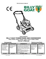
2. Operation2.1 Unit Appearance <strong>and</strong> Part Names<strong>PDS185</strong>S-6B4A0301321. Exhaust outlet2. Lifting bail3. Door4. H<strong>and</strong>le5. Service valve6. Drawbar7. Instrument panel2-1
2. Operation2.4 Compressed <strong>Air</strong> Service Valve2.4.1 Service Valve (20A)Open the valve by turning the h<strong>and</strong>le clockwise, <strong>and</strong> close itby turning the h<strong>and</strong>le counterclockwise.OpenClose2.5 DoorTR06422.5.1 Open/Close the Door• Keep the door closed <strong>and</strong> locked while running the unit.• When the door has to be opened, be careful not to touchportions that are rotating or very hot.Careless touch may cause serious injury.PK0028• Pull the h<strong>and</strong>le forward to open the door.• Be sure to close the door tightly so that its latch is firmly caught.2.6 Check before Starting UnitCheck before starting the unit• Be sure to check the unit before operation.When any abnormality is found, be sure to repair it before restarting the unit.• Be sure to make daily checks before operation. If the unit is operated without prior check <strong>and</strong> withoutnoticing its abnormality, such operation could cause seizure of components or may even cause fire.2-5
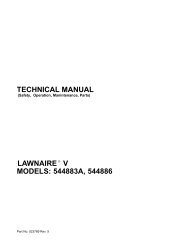
2. Operation2.6.1 Check Items <strong>and</strong> Locations3 2 41<strong>PDS185</strong>S-6B41<strong>PDS100</strong>S-6B4PDS130S-6B465 7 8A0502331. Check fuel2. Check V-belt tension3. Check coolant level4. Drain water sedimenter5. Draining of separator receiver tank6. Check compressor oil level7. Drain fuel tank8. Check engine oil levelCheck wiring of each partCheck piping of each part2-6
2. Operation2.6.2 Check Engine Oil Level• Unit should be on level before checking oil level.• When you check oil level after you have once started operation, wait 10 to 20 minutes afterstopping engine, before checking the oil level.(Procedure) Pull out the engine oil dipstick, <strong>and</strong> wipe it with a cleancloth. Then, re-insert the dipstick fully <strong>and</strong> pull it out again. Ifthe dipstick shows the oil level between HIGH <strong>and</strong> LOW, itis normal. When the oil level is below its LOW, add engine oil.(See 5.6.1)• While checking oil level, check also for contamination. If theoil is found dirty, contaminated or should it be changedaccording to the periodic inspection list, change the oil.(See 5.6.1)• Never fill oil more than HIGH level.When oil level iswithin this zone,it is normal.LOWHIGHA0502322.6.3 Check Coolant LevelTaking off the radiator cap• Be sure to stop the machine <strong>and</strong> allow time to cool. Then loosenthe radiator cap one notch. After the coolant water is sufficientlycooled <strong>and</strong> the inner pressure is released, take the cap off.If this procedure is neglected, the inner pressure can blow offthe cap. Steam jetting out of the radiator could result in causingscalding. Follow this procedure under all circumstances.H990432• Check the coolant level in the reserve tank. If it is lowerthan the limit, open the cap <strong>and</strong> replenish the coolant.(Level must be kept above LOW mark.)• If little coolant is left in the reserve tank, replenish theradiator with cooling water. (See 5.6.15)LOWH0000362-7
2.6.4 Check <strong>Compressor</strong> Oil Level2. OperationRefilling of compressor oil• When you refill the separator receiver tank with compressor oil,stop the engine, <strong>and</strong> make sure that the pressure gaugeindicates psi (0 bar) <strong>and</strong> there is no residual pressure in it, <strong>and</strong>then gradually loosen the oil filler cap for refilling oil.• Note residual pressure in the receiver tank could force bothextremely hot compressed air <strong>and</strong> oil to jet out <strong>and</strong> you may bescalded or seriously injured.W010• Place the machine on level ground when checking the oillevel.• Check the oil level of the compressor. Correct oil level isbetween upper <strong>and</strong> lower limit of the gauge, when the unitstops. If the gauge shows lower than the middle level,replenish oil. (See 5.6.5)H0000372.6.5 Draining of Separator Receiver Tank• After stopping the engine, confirm that the pressure gaugeindicates 0 psi (0 bar) <strong>and</strong> there is no residual pressure in it,then open the drain valve gradually to drain the compressor oil.• Note residual pressure in the receiver tank could force bothextremely hot compressed air <strong>and</strong> oil to jet out <strong>and</strong> you may bescalded or seriously injured.Draining of Separator receiver tankH990432• Gradually opening the drain valve 2fitted under theseparator receiver tank1as shown in the fig, drain thecondensate.• Be careful not to fully open the valve. Otherwise, much oilmay be lost.• After draining the oil completely, close the drain valve2firmly.• Drain the condensate in container4, dispose of the wasteoil according to the designated regulations.1324H0000382-8
2. Operation2.6.6 Check FuelFire prevention• Do not, under any circumstance, smoke cigarettes or lightmatches during fueling.• Fuel is extremely flammable <strong>and</strong> dangerous. It therefore, couldcatch fire should it flame or other sources of ignition be broughtnear fuel. Ensure that the engine is cool. Never fuel a hotmachine.• Refuel only after stopping the engine, <strong>and</strong> never leave an openfuel can near the machine. Do not spill. It could cause a fire.When it is spilt, wipe it up completely.• Refilling fuel tank should be done in an outdoor well-ventilatedplace.D004Choose appropriate fuel• Be sure to use diesel fuel oil for diesel engine use.(Using other oil will cause low power or damage to the engine.)• Check fuel level gauge before operation. Replenish enough fuel to prevent fuel shortage duringoperation, if the level is low.• When refueling, fill a fuel tank up to the base of fuel filler port4. Never overfill fuel because itmay cause fuel leakage.• Be sure to fasten the fuel tank cap firmly after replenishment. If fuel is spilt, wipe it upcompletely.2.6.7 Drain Fuel Tank• Opening the drain valve2fitted under the fuel tank1,drain the condensate from the tank.• When completely drained, firmly close the drain valve 2.• Drain the condensate in container3 , dispose of condensateaccording to the designated regulations.4123H0000392-9
2. Operation2.6.9 Check V-Belt Tension• Too tight belt tension could damage shaft <strong>and</strong> shorten bearing life. Too loose belt tension may result indamaging belt earlier <strong>and</strong> machine components due to overheat.Follow the procedure below to adjust tension of fan belt <strong>and</strong> V-belt for alternator.[<strong>PDS100</strong>S,130S-6B4](Procedure) Adjust the tension by gradually loosening the fastening boltof the alternator. Visually check if there are any cracks or tears in the belt. Loosen the fastening bolt of the alternator until the play ofthe belt reaches 0.2 to 0.3 in. (6.0 to 8.0 mm) when pushedby fingers, <strong>and</strong> adjust it. Be careful not to leave any grease or LLC * on a belt whilechanging it. If any such material is left, wipe it offcompletely.* Long life coolant0.2 to 0.3in.[110bf(49N)]H000041E-2[<strong>PDS185</strong>S-6B4](Procedure) Adjust the tension by gradually loosening the fastening boltof the alternator. Visually check if there are any cracks or tears in the belt. Loosen the fastening bolt of the alternator until the play ofthe belt reaches 0.32 to 0.45 in. (8.0 to 12.0 mm) whenpushed by fingers, <strong>and</strong> adjust it. Be careful not to leave any grease or LLC * on a belt whilechanging it. If any such material is left, wipe it offcompletely.* Long life coolant0.32 to 0.45in.[22lbf(98.1N)]H000041E-22-11
2. Operation2.6.10 Check Wiring of Each PartCheck each wiring for any loose connection, damage to insulating sheathed portion, disconnection,<strong>and</strong> short-circuit.2.6.11 Check Piping of Each PartCheck each piping for any loose connection <strong>and</strong> also check each hose <strong>and</strong> pipe for any tear <strong>and</strong> leaks.2.7 Unit OperationOperation with compressed air supply port opened is prohibited• Do not operate the machine with service valves <strong>and</strong> relief valveopen unless air hoses <strong>and</strong>/or pipes are connected.High-pressurized air blows out <strong>and</strong> its air pressure could causeinjury to the people nearby.• When the machine has to be unavoidably temporarily operatedwith its port open, be sure to mount a silencer to reduce noise<strong>and</strong> wear protective materials such as earplugs to preventdamage to hearing.D003Quick Glow System• Since this equipment is provided with a quick glow system (quick preheating device), you do nothave to turn the starter switch counterclockwise from STOP position.• Turn the starter switch to the “RUN” position, <strong>and</strong> the preheating will be completed in severalseconds <strong>and</strong> the preheating lamp will go out. Then, turn the Starter Switch to the Start positionto start up the engine.• When the engine is already warm, the preheating operation is automatically omitted. Eventhough the preheating lamp lights up momentarily, ignore the lamp status, <strong>and</strong> start up theengine.WARNING – Because of the quick glow system, never use starting fluids to start engine.2-12
2. Operation2.7.2 Operating Procedures when Engine Fails to Start up on First Attempt• When the engine fails to start up even after performing the startup procedures to do notkeep the starter running, but set the starter switch back to ”STOP” <strong>and</strong> wait about 30 seconds.Then, repeat the startup procedure once again.• If the repeated procedure does not allow the engine to run, the following causes are suspected.Check the following:No fuelClogging of fuel filterClogging of filter inside the fuel air bleeding electromagnetic pumpDischarge of battery (Low cranking speed)2.7.3 EFPA (Electrical Fuel Primer <strong>and</strong> <strong>Air</strong> Bleed)If the unit runs out of fuel, the electromagnetic pump attached to the unit will automaticallybleed air out of the fuel system. (After draining sediment from water sedimenter or changingfuel filter with a new one, bleed the air in the same procedure as below.)(Procedure) Replenish fuel. Turn the starter switch to its “RUN” position. The electromagnetic pump starts pumping <strong>and</strong>automatically bleed air caught in the fuel pipes. <strong>Air</strong>-bleeding will be completed within 40 to 50 seconds. Start the machine following the starting procedures mentioned in 2.7.1. If starting fails one time,repeat the abovementioned procedures.• After finishing the air bleeding operation, never leave the starter switch placed on “Run” positionbecause the battery is discharging.2.7.4 Operation under Cold Weather ConditionsWhen it is difficult to start engine in cold weather, take thefollowing measures.(Procedure) Close all the service valves <strong>and</strong> fully open the relief valve1provided at the front of the separator receiver tank. When engine starts after performing the startup procedure,gradually close the relief valve, watching the rise of enginerevolutions. Then after closing the valve fully, performwarming-up operation in this state.PDS130S-6B4<strong>PDS185</strong>S-6B4CloseOpen1A030143Operation under Cold Weather Conditions below 23°F (-5°C)• Use SAE10W-30 (CD class) for the engine oil.• Use LLC (antifreeze). Use correct amount to provide freeze protection, according to the ambienttemperature.• Battery should always be kept fully charged.2-14
3.1 Transportation3. Transportation <strong>and</strong> Towing the UnitTransportation• When loading <strong>and</strong> unloading unit, be sure to use the lifting bail provided on the center of the unit top.• Never get under the unit which is lifted up, because it is very dangerous.• When unit is transferred or moved from working site, be sure to place it on truck bed, <strong>and</strong> fasten it byropes at the front eye <strong>and</strong> rear st<strong>and</strong>. Also be sure to put a set of chocks to fix its wheels firmly on thetruck bed.• Never lift unit which is still in operation, or it could cause critical damage to each component or lead toserious accident.• When lifting unit up, make sure that all the fixing bolts on the bonnet are surely tightened because it isfeared that the unit may fall.• If towing unit : Make sure machine is towed level.• Check tire pressure <strong>and</strong> tire condition before towing.• Attach safety chains <strong>and</strong> use correct tow hitch.• Check operation of lights <strong>and</strong> brakes before towing.• Check wheel lug nuts for proper torque.Lifting up Before lifting the unit up, make sure to check the lifting bail for any crack <strong>and</strong> loosened bolts. Connect the hook1of the crane or shackle with lifting bail2eye fitted at the top center of the unit, <strong>and</strong> make surethat there is no person st<strong>and</strong>ing around the unit. Thenperform hoisting operation. Use an auxiliary rope3<strong>and</strong> communicate with the otherpersonnel using signs <strong>and</strong> signals while lifting operation, sothat no swinging motion or twisting happens to the liftedunit. Select a truck or a crane with capacity sufficient for weight<strong>and</strong> size of the unit by referring to the values shown inChapter 8 “Specifications“ of the manual.A000053Lowering the unit from the truck bed pulling down• Lower the unit down onto a level place which can sustain the weight of the unit.• After placing the unit down, put chocks to lock the wheels before unfastening the crane’s shackles.3-1
3.2 Towing the Unit3. Transportation <strong>and</strong> Towing the Unit• Before towing the unit, check the following points <strong>and</strong> be sure to repair failures, if any:• <strong>Air</strong>-pressure in the tires.• Loose wheel bolts or nuts.• Abnormal wear or damage to the tires.• Damage of drawbar.• Be sure to use a vehicle with enough capacity to tow the unit in operating weight.• Do not tow the unit without unfastening tool, equipment, <strong>and</strong> hoses.Keep h<strong>and</strong>s <strong>and</strong> fingers clear during hook-up or unhooking drawbar.• If you do not follow the above instructions, it could cause serious injury or big damage.3-2
4.1 Location <strong>and</strong> Installation4. Installation• Exhaust gas from the engine is poisonous, <strong>and</strong> could causedeath when inhaled.Avoid using the machine in an insufficiently ventilated building ortunnel.• Do not position the exhaust gas outlet in direction of a person ora house.VentilationPC002• The machine has to be parked horizontally on a level place.• In case the machine has to be parked on a slope, place it acrossgrade so that the machine does not tend to roll downhill.• Grade on a slope shall be within 15 degrees• Be sure to put one set of chocks1to the wheels.A000054• The machine should be operated in following conditions:• Ambient temperature 5°F to 104°F (-15°C to +40°C)• Humidity Less than 90%• Altitude Lower than 1,500 m above sea level• Install the machine in a place with good ventilation, lower temperature <strong>and</strong> with surroundings asdry as possible.• If more than two machines are placed parallel in operation, keep enough distance so that exhaustair from one machine does not affect the other one.• Also, a machine has to be installed in the environment where fresh air is always available.• Keep enough space around the unit for inspection <strong>and</strong> maintenance access.4-1
5. Periodic Inspection/Maintenance5.1 Important Items at Periodic Inspection <strong>and</strong> Maintenance or afterMaintenanceThe manual shows proper interval for periodic inspection <strong>and</strong> maintenance under normallyoperating conditions. Inspection <strong>and</strong> maintenance should be performed more often underextremely harsh conditions.Hang a “Now Checking <strong>and</strong> under Maintenance” tag• Remove the starter key from the starter switch before startinginspection, <strong>and</strong> hang up a “Now Checking <strong>and</strong> underMaintenance” tag where it can be easily seen. The checker mustkeep the key during checking <strong>and</strong> maintenance.• Remove the negative (–) side cable from the battery.If the above procedure is neglected, <strong>and</strong> another person startsoperating the machine during check or maintenance, it couldcause serious injury.• Use tools appropriate for the inspection <strong>and</strong> maintenance. Anymakeshift or improper tools could cause unexpectedly injury bytheir slippage.SY001For protecting oil separator from fire accident• Be sure to perform oil change basically according to thespecified interval. But if such oil is found much morecontaminated before the interval, change the oil even before thespecified period comes. In doing so, replace the oil completely<strong>and</strong> use our recommended oil.• Be sure to perform following periodic inspection <strong>and</strong>maintenance:1. Check <strong>and</strong> change compressor oil2. Change oil separator• Never mix the oil of different br<strong>and</strong>s, or the mixed oil maydeteriorate the oil quality.21H0000465-1
5. Periodic Inspection/MaintenancePrecautions for check <strong>and</strong> maintenance• Be sure to use recommended fuel, oil, grease, <strong>and</strong> antifreeze.• Do not disassemble or adjust engine, compressor or part(s) for which inspection or maintenance is notreferred to in this manual.• Use genuine parts for replacement.• Any breakdown, caused by using unapproved parts or by wrong h<strong>and</strong>ling, will be out of the scope of“WARRANTY”.• Keep the electrical components away from water or steam.• Waste from machines contains harmful material. Do not dispose of such harmful fluids to the ground,rivers, lakes or ponds, <strong>and</strong> sea. It contaminates the environment.• When draining waste fluid from machines, use leakproof containers to hold such fluids from machine.• Be sure to follow the designated regulations when disposing of oil, fuel, coolant, filters, battery <strong>and</strong> otherharmful things.5.2 Daily Inspection <strong>and</strong> Operation Log• Be sure to carry out daily inspection every morning before operation. See Chapter 2 “Operation” ofthe manual for the details of inspection.• Pay attention to <strong>and</strong> carefully observe the following points during daily operation or inspection<strong>and</strong> maintenance work. If any trouble or abnormality is found, immediately investigate its cause<strong>and</strong> make repairs. If the cause is unknown or not traceable, or if the trouble involves a part orcomponent not described in the manual, ask your nearest dealer for information.(a)Controls <strong>and</strong> instruments function properly.(b)Quantity <strong>and</strong> any leak of water, fuel, <strong>and</strong> oil or anycontamination should be checked.(c)Appearance, abnormal noise or excessive heat should bechecked.(d)Loose bolt or nut should be checked.(e)Any damage, wear or shortage of machine components <strong>and</strong>parts should be checked.(f)Performance of each part or component should be proper.TR0049• Keep the operation log to record constant inspection of each component, so that trouble of the unitcan be easily discovered <strong>and</strong> preventive measures can be taken.It is very useful to record information such as discharge pressure, oil level, as well as running hour,maintenance items <strong>and</strong> replenishment of lubricant on a daily maintenance log.5-2
5. Periodic Inspection/Maintenance5.3 Periodic Inspection List<strong>Compressor</strong>MaintenanceDailyEvery250Every300Every500Every1,000Every2,000(Unit:Hour)Check compressor oil level. 2-8Drain of separator receiver tank. 2-8Check looseness in pipe connecting part, <strong>and</strong> wear<strong>and</strong> tear of pipe. 2-12Check oil, water, fuel <strong>and</strong> air leak. 2-15Check performance of gauge <strong>and</strong> indication lamps. 2-15Change compressor oil. 1 5-9Change compressor oil filter. 1 5-10Clean strainer in the scavenging orifice. 5-10Clean <strong>and</strong> change air filter element. 5-11(Clean)(Change)Clean outside of oil cooler. 5-13Change speed regulator diaphragm. 5-12Change oil separator. 5-15Change nylon tubes. 5-15Change unloader of o-ring.Every3,000Page5-16Changespacerofunloader. 2 Change pressure regulator. 5-16Check rubber hoses.Check o-ring <strong>and</strong> needle valve of auto-relief valve.5-165-16Such items marked shall be carried out by customers.For the following items or clauses marked , contact us directly or our distributors because theyrequire expert technical knowledge on them.The following table shows the inspection <strong>and</strong> maintenance intervals under normal operation conditions.In case the unit is operated under harsh environmental conditions <strong>and</strong> operation conditions, theintervals should be shortened.The items or parts marked 1 show that they should be replaced primarily.The items or parts marked should be replaced every two years even if they are not in disorder withintheir periodical maintenance interval because their materials will change or become degraded as timepasses.Also for the same reason, the parts marked should be replaced every three years.Regardingtheitemmarked 2 check the function of the unloader. In case the unloader malfunctions,change O-ring or bushing of unloader. This is because either of both parts may be worn out.5-3
5. Periodic Inspection/MaintenanceEngineRefer to engine operation manual for inspection <strong>and</strong> maintenance of an engine.Drain fuel tank(Including sedimenter).MaintenanceDailyEvery50Every250Every500Every1,000Every2,000Every3,000(Unit:Hour)Every8,000Page 2-9Check fuel level 2-9Check engine oil level. 2-7Check coolant level. 2-7Check looseness in pipe connectors, terminals <strong>and</strong>tear in wiring. 2-12Check V-belt tension. 2-11Change engine oil. 5-7Change engine oil filter. 5-8Check battery electrolyte. 5-8Change filter for air bleeding electromagnetic5-12pump.(<strong>PDS185</strong>S only)(Change)Clean <strong>and</strong> change air-filter element.(Clean)(Change)5-11Change fuel filter. 5-11Change sedimenter element <strong>and</strong> O-ring.(<strong>PDS100</strong>S,130S only) 5-12Change coolant. 5-14Clean inside of radiator. 5-13Clean outside of radiator. 5-13Change rubber hose. 5-15Clean inside of fuel tank. 5-15Change radiator hoses. 5-16The items or parts marked show that they should be replaced primarily.The items or parts marked should be replaced every two years even if they are not in disorder withintheir periodical maintenance interval because their materials will change or become degraded as timepasses.Also for the same reason, the parts marked should be replaced every three years.5-4
5. Periodic Inspection/Maintenance5.4 Periodic Replacement of Parts5.4.1 FiltersPart Name Part Number Quantity<strong>PDS100</strong>S-6B4 SHIBAURA 140517020 1Engine oil filterPDS130S-6B4 SHIBAURA 140517020 1<strong>PDS185</strong>S-6B4 NISSAN 15208 43G00 1<strong>Compressor</strong> oil filter 37438 05201 1<strong>PDS100</strong>S-6B4 32143 11700 1<strong>Air</strong> filter elementPDS130S-6B4 32143 11800 1<strong>PDS185</strong>S-6B4 32143 12700 1Element4 SHIBAURA 360720060 1O-ring5 <strong>PDS100</strong>S-6B4 SHIBAURA 052100440 1Fuel filter Element4 SHIBAURA 360720060 1O-ring5 PDS130S-6B4 SHIBAURA 052100440 1Element <strong>PDS185</strong>S-6B4 NISSAN 16403 J5500 1Element4 SHIBAURA 130366110 1SedimenterO-ring5 <strong>PDS100</strong>S-6B4 SHIBAURA 052100440 1Element4 SHIBAURA 130366110 1O-ring5 PDS130S-6B4 SHIBAURA 052100440 1Oil separatorSeparator 34220 12801 1O-ring 03402 15140 1Filter for electromagnetic pump <strong>PDS185</strong>S-6B4 43540 05600 15.4.2 Diaphragms & O-RingsPart Name Part Number QuantityDiaphragm of speed regulator 36437 01500 1Pressure regulator 36400 19000 1O-ring1 03402 25021 1Auto-relief valveO-ring2 03402 25008 1O-ring3 21221 02100 1Needle valve4 36429 00800 1O-ring of unloader 21441 03000 15-5
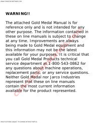
5. Periodic Inspection/Maintenance5.5 Items <strong>and</strong> Places of Inspection1 2 3 4 5 6 7 89,10,111213141516 17 18<strong>PDS185</strong>S-6B4A0301391. Change pressure regulator2. Change O-ring of unloader3. Change air filter element4. Change diaphragms of speed regulator5. Change engine oil filter6. Change engine oil7. Change radiator hoses8. Change fuel filter9. Clean outside of the radiator <strong>and</strong> oil cooler10. Clean inside the radiator11. Change coolant12. Change oil separator13. Clean strainer in the scavenging orifice14. Check O-ring <strong>and</strong> needle valve in theauto- relief valve15. Change compressor oil16. Check battery17. Change compressor oil filter18. Clean inside the fuel tank• Change nylon tubes• Change rubber hoses <strong>and</strong> pipes5-6
5. Periodic Inspection/Maintenance5.6.5 Change <strong>Compressor</strong> Oil• At 300 hours for the first change <strong>and</strong> every 500 hours thereafterRefilling of compressor oil• When you refill the separator receiver tank with compressor oil,stop the engine, <strong>and</strong> make sure that the pressure gaugeindicates 0 psi (0 bar) <strong>and</strong> there is no residual pressure in it, <strong>and</strong>then gradually loosen the oil filler cap for refilling oil.• Note residual pressure in the receiver tank could force bothextremely hot compressed air <strong>and</strong> oil to jet out <strong>and</strong> you may bescalded or seriously injured.W010Do not mix compressor oil• Be sure to use recommended oil listed below.• Viscosity of the oil varies depending on the temperature <strong>and</strong> other environmental conditions.• Select one from the recommended oil listed below.Maker <strong>and</strong> Br<strong>and</strong> of Recommended OilMakerBr<strong>and</strong>HULS ANDEROL 3032MOBIL RARUS SHC 1024TEXACOSYN-STAR DE32• Even continuous oil replenishment cannot improve its deteriorated condition. Be sure to change the oilcompletely at every scheduled interval.• Do not mix it with other br<strong>and</strong> oil, or it will cause poor performance <strong>and</strong> shorten the life of thecompressor oil. (But fresh compressor oil could accept a mixture of small amount of different br<strong>and</strong>s.)• Running the unit with old <strong>and</strong> deteriorated compressor oil will cause damage to bearings, or seriousaccident like ignition in a separator receiver tank. Be sure to change the oil completely at everyscheduled interval.• Follow the designated regulations to dispose of compressor oil.5-9
5. Periodic Inspection/Maintenance5.6.13 Clean outside of Radiator <strong>and</strong> Oil Cooler• Every 1,000 hours • When the fin tubes1of a radiator <strong>and</strong> an oil cooler areclogged with dust or other foreign materials, the heatexchange efficiency drops <strong>and</strong> this will raise coolanttemperature <strong>and</strong> discharge air temperature. These tubes <strong>and</strong>fins should be cleaned depending on the state of clogged fintubes 1even before 1,000 hours maintenance schedule.• Do not use a high pressure washer to protect fin tubes frombeing damaged.1 H0000545.6.14 Clean inside of Radiator• Every 1,000 hours • When the inside of a radiator <strong>and</strong> water conduits of an engine are dirty with scale <strong>and</strong> rust, itscooling efficiency will be deteriorated. Clean the interiors of such components periodically.• Ask your nearest dealer for such inner cleaning.5-13
5.6.15 Change Coolant5. Periodic Inspection/Maintenance• Every 1,000 hours or every 2 yearsTaking off the radiator cap• Be sure to stop the machine <strong>and</strong> allow time to cool. Then loosenthe radiator cap one notch. After the coolant water is sufficientlycooled <strong>and</strong> the inner pressure is released, take the cap off.If this procedure is neglected, the inner pressure can blow offthe cap. Steam jetting out of the radiator could result in causingscalding. Follow this procedure under all circumstances.H990432How to h<strong>and</strong>le LLC (Antifreeze)• LLC (Antifreeze) is a toxic material.• When a person has injested LLC (Antifreeze) by accident, seek medical attention immediately.• When a person gets LLC (Antifreeze) in his eyes, wash the eyes with clean running water <strong>and</strong>make him see a doctor immediately.• When LLC (Antifreeze) is stored, put it in a container with an indication saying “LLC(Antifreeze) inside” <strong>and</strong> seal it up, then keep it in a place away from children.• Beware of flames.Quality of coolant <strong>and</strong> antifreeze• Use soft water of good quality such as tap water for coolant.• When water with dirt, s<strong>and</strong>, <strong>and</strong>/or dust contained, or hard water such as well water (ground water) isused, this will cause deposits inside radiator or on cylinder head, <strong>and</strong> will cause engine overheat due topoor flow of coolant.• When replacing coolant, be sure to install a coolant filter <strong>and</strong> add coolant.• When the unit is used in a cold region <strong>and</strong> possible freezing is expected, it is recommended to use LLC(Antifreeze) for the coolant.• Adjust mixing ratio of LLC (Antifreeze) with water according tothe temperature.• Use LLC (Antifreeze) within the range of its mixing ratiobetween 35 <strong>and</strong> 60%.• If LLC (Antifreeze) in the water exceeds more than 60%, itmay decrease its antifreezing effect.• Follow the designated regulations to dispose of LLC(Antifreeze).Reference of LLC (Antifreeze)mixing ratioTemperature Mixing ratio–4°F (–20°C) 35%–40°F (–40°C) 55%5-14
6.1 Adjustment of Regulator6. Maintenance/AdjustmentDo not run the compressor with compressed air supply port open• When adjusting the regulator, be sure to mount a silencer atthe discharge opening to eliminate sound. Wear protectivematerials such as earplugs to prevent hardness of hearing.D003• Regulator is pre-adjusted at delivery from the plant. Never turn the bolt <strong>and</strong> rod. Otherwise it leadsto maladjustment.• In accordance with the following adjustment procedures, make sure to set engine revolutions tomake governor lever contact high-speed stopper at full load. If the pressure in separator receivertank with engine speed set lower than rated speed drops lower than 44 psi (3 bar) discharge airtemperature could rise so much to cause a serious trouble.• Be sure to follow the procedure below when the component is required to be re-adjusted (such aswhen the unit has been disassembled).• Ask your nearest dealer if you have any questions.(Procedure) Stop the compressor <strong>and</strong> adjust the length of the rod3which is connected to the speed regulator2 untilits engine governor lever1is pulled fully to itshigh-speed side. (By shortening length of “L”, theregulator increases high-speed.) If the engine governorlever1does not reach the end of stopper4at itshigh-speed side, sufficient speed of the engine, at itsfull-load condition, cannnot be obtained. There is noneed for unload revolution readjusttment. Adjust the pressure regulator 5 by turning itspressure adjustment screw6, so that the speedregulator2starts its actuation <strong>and</strong> decreases theengine speed when the pressure exceeds 100 psi (6.9bar). (Pressure increases by tightening the screw, <strong>and</strong>decreases by loosening the screw.)2 3 4 1<strong>PDS100</strong>S-6B4PDS130S-6B42 3L<strong>PDS185</strong>S-6B44HighSpeed1HighSpeedLowSpeedA040309LowSpeedA00007465H0000596-1
6.2 Maintenance of Battery6. Maintenance/AdjustmentH<strong>and</strong>ling battery• Keep flames away from battery.• Battery generates hydrogen gas <strong>and</strong> may explode.• Therefore, recharging should be done at a well-ventilatedplace.• Do not allow sparks or flame near the battery.• Do not check the battery by short-circuiting the positive <strong>and</strong>negative terminals.• Never operate the machine nor charge the batteries with thebattery liquid level being kept lower than the "LOWER" level.Continuing operation at this lower level will cause deteriorationof such parts as pole plates etc., <strong>and</strong> also it may causeexplosion as well as reduction of battery life. Add distilled waterso that the liquid level may reach the middle level between the"UPPER" <strong>and</strong> "LOWER" level without any delay.• Do not charge a frozen battery. Otherwise it may explode. If thebattery is frozen, warm it up until the battery temperaturebecomes 61°F to 86°F (16°C to 30°C).• Battery electrolyte is dilute sulfuric acid.In case of mish<strong>and</strong>ling, it could cause skin burning.• When you deal with a battery, please be sure to wear protectionimplements, such as protection glasses <strong>and</strong> a glove.• When such battery electrolyte contacts your clothes or skin,wash it away with large amount of water immediately.• If the battery electrolyte gets into your eyes, wash it awayimmediately with plenty of water <strong>and</strong> seek medical attention.• Dispose of battery, observing local regulations.D004W010TR0093Do not connect the cables backwards• If a booster cable has to be used or when cables are connected at battery replacement, be careful notto connect (+) <strong>and</strong> (–) terminals backwards. A wrong-connection will cause spark <strong>and</strong> damagecomponents. Explosion may result.6-2
6. Maintenance/AdjustmentSymptom Cause CountermeasuresEngine oilpressure lamp goeson.(1) Engine oil shortage.(2) Engine oil filter clogging.(3) Malfunction of engine oil pump(4) Faulty oil pressure switch.(5) Loosened or disconnected wiring orconnector.Replenish oilChangeChangeChangeCheck/FastenCoolanttemperature lampgoes on.Discharge airtemperature lampgoes on.Fuel residual levellamp goes on.(1) Radiator clogging.(2) Faulty thermostat.(3) Faulty coolant temperature switch.(4) Shortage of coolant.(5) Slippage of fan belt.(6) Looseness, disconnection of wiring orconnectors.(1) Oil cooler clogging.(2) Oil filter clogging.(3) Faulty discharged air temperatureswitch.(4) Looseness, disconnection of wiring orconnectors.(5) Slippage of fan belt.(6) Shortage of compressor oil.(7) Malfunction of by-pass valve.(1) Fuel runs short.(2) Malfunction of sending unit for fuel oillevel drop.(3) Loosened <strong>and</strong> disconnected wiringconnection <strong>and</strong> connectors.• Contact your nearest dealer if you find it difficult to repair by yourselves.• Refer to the engine operation manual for trouble concerning the engine.CleanChangeChangeReplenishAdjust tensionCheck/FastenCleanChangeCheck/ChangeCheck/FastenAdjust tensionReplenish oilAdd fuel oilInspect/replaceInspect/retighten6-5
6.3 Troubleshooting6. Maintenance/Adjustment• Should any trouble occur during operation, do not leave it. Investigate the cause <strong>and</strong> takeappropriate measures.• Read the manual carefully <strong>and</strong> fully underst<strong>and</strong> what to do in case of trouble.• The better you underst<strong>and</strong> the construction <strong>and</strong> function of the unit, the faster you can find aproblem <strong>and</strong> solution.• This chapter describes the state, cause <strong>and</strong> countermeasures of important troubles in detail:Symptom Cause CountermeasuresLow starterrevolution speed.(1) Battery malfunction. Check batteryCharge, changeStarter rotates butengine does notstart.(1) Fuel filter clogging.Discharge airpressure does notreach 100 psi (6.9bar).Engine does notreach itsmaximum speed.Revolution dropsbefore dischargeair pressurereaches 100 psi(6.9 bar).Engine does notreach minimumrevolution atunload.Safety valverelieves at unload.Oil mixes in <strong>Air</strong>.(Poor oilseparation)Insufficient free airdelivery.(2) Malfunction of fuel cut solenoid ormotor stopper.(3) No fuel.(1) Pressure regulator insufficient adjustment.(2) Starting unloader valve is left at itsstart position.(1) Improper length in speed regulator rod.(2) Unloader orifice clogging.(3) Faulty speed regulator.(4) Engine trouble.(5) Fuel filter clogging.(1) Pressure regulator insufficientadjustment.(2) Trouble of pressure regulator.(3) Unloader orifice clogging.(1) Improper length in speed regulator rod.(2) Faulty speed regulator.(1) Pressure regulator insufficientadjustment.(2) Speed regulator diaphragm damaged.(3) Unloader valve damaged <strong>and</strong> seatmalfunction.(4) Faulty safety valve.(5) Improper length of speed regulator rod.(1) Scavenging orifice strainer clogging.(2) Excessive oil in tank.(3) Low discharge pressure.(4) Oil separator deteriorated.(1) <strong>Air</strong> filter element clogging.(2) Unloader valve cannot fully open.(3) Engine does not reach rated speed.Disassemble, clean, <strong>and</strong>changeCheck fuseChange solenoid or motorstopperCheck connectorReplenish fuelRe-adjust (Fasten)Place it at “RUN” positionRe-adjustDisassemble/CleanDisassemble/CheckCall your nearest dealerDisassemble/ChangeRe-adjust (Fasten)ChangeDisassemble/CheckRe-adjustDisassemble/CheckRe-adjust (loosen)ChangeChangeChangeRe-adjust (elongate)Disassemble/CleanDrain to its proper levelDisassemble unloader/CheckDisassemble/ChangeClean element or changeCall your nearest dealerSee 6.1.6-4
7. Storage of the Unit7.1 Preparation for Long-term StorageWhen the unit is to be kept unused in storage for a long time, be sure to follow the preparationsbelow <strong>and</strong> put the unit in a dry <strong>and</strong> less dusty place.• Put the unit in a temporary cabin if it is stored outside. Avoid leaving the unit outside with a sheetcover directly on the paint for a long time, or this will cause rust to the unit.• Perform the following treatments at least once every three months.(Procedure) Drain existing lubricant from the engine oil pan. Pour new lubricant in the engine to clean itsinside. After running it for a while, drain it again. Spread lubricant on moving parts like speed regulator <strong>and</strong> rod end, beforeh<strong>and</strong>. Completely charge the battery <strong>and</strong> disconnect grounding wires. Remove the battery from the unit,if possible, <strong>and</strong> store it in a dry place. (Charge the battery at least once every month.) Drain coolant <strong>and</strong> fuel from the unit. Seal the engine, air-intake port <strong>and</strong> other openings like the muffler with a vinyl sheet, packingtape, etc., to prevent moisture <strong>and</strong> dust from getting in the unit. Be sure to repair any trouble <strong>and</strong> maintain the unit so that it will be ready for the nextoperation.7-1
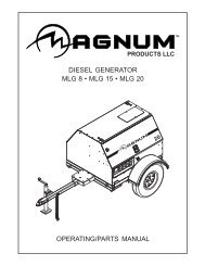
8.1 <strong>Compressor</strong> Specifications8. Specifications<strong>PDS100</strong>S-6B4General SpecificationsOverall lengthOverall length(bonnet only)Overall widthOverall heightNet dry massOperating massFuel tank capacityin.(mm)in.(mm)in.(mm)in.(mm)lb(kg)lb(kg)gal.(L)106(2,680)62(1,580)57(1,450)55(1,395)1,742(790)1,907(865)18.5(70)<strong>Compressor</strong>EngineTypeFree air deliveryWorking pressureLubricating systemDriving systemReceiver tankcapacityLubricating oilcapacityModelTypeNumber of cylinders,bore strokeTotal displacementRated outputLubricating oilcapacityCoolant capacity(including radiator)Batterycfm(m 3 /min)psi(bar)cu in.(m 3 )gal.(L)in.(mm)cu in.(L)hp/rpm(kW/min -1 )gal.(L)gal.(L)Single-stage oil cooled,screw type compressor100(2.85)100(6.9)Forced lubrication bycompressed pressureDirect driving withgear coupling1,833(0.030)3.7(14)SHIBAURA S773L-CWater-cooled 4-cyclepre-chamber type3-3.03in.3.19in.3-77mm81mm69(1.131)27.1/3,425(20.2/3,425)1.3(4.9)1.2(4.5)80D26RMFOutline drawingUnit:in.(mm)A0502368-1
8. SpecificationsPDS130S-6B4General SpecificationsOverall lengthOverall length(bonnet only)Overall widthOverall heightNet dry massOperating massFuel tank capacityin.(mm)in.(mm)in.(mm)in.(mm)lb(kg)lb(kg)gal.(L)106(2,680)62(1,580)57(1,450)55(1,395)1,940(880)2,116(960)18.5(70)<strong>Compressor</strong>EngineTypeFree air deliveryWorking pressureLubricating systemDriving systemReceiver tankcapacityLubricating oilcapacityModelTypeNumber of cylinders,bore strokeTotal displacementRated outputLubricating oilcapacityCoolant capacity(including radiator)Batterycfm(m 3 /min)psi(bar)cu in.(m 3 )gal.(L)in.(mm)cu in.(L)hp/rpm(kW/min -1 )gal.(L)gal.(L)Single-stage oil cooled,screw type compressor130(3.7)100(6.9)Forced lubrication bycompressed pressureDirect driving withgear coupling1,833(0.030)3.7(14)SHIBAURA N843L-CWater-cooled 4-cycledirect injection3-3.31in.3.94in.3-84mm100mm101(1.662)37.5/3,000(28.0/3,000)1.6(6)1.7(6.5)80D26RMFOutline drawingUnit:in.(mm)A0402908-2
8. Specifications<strong>PDS185</strong>S-6B4General SpecificationsOverall lengthOverall length(bonnet only)Overall widthOverall heightNet dry massOperating massFuel tank capacityin.(mm)in.(mm)in.(mm)in.(mm)lb(kg)lb(kg)gal.(L)127(3,226)73(1,850)57(1,450)55(1,395)2,249(1,020)2,480(1,125)24(90)<strong>Compressor</strong>EngineTypeFree air deliveryWorking pressureLubricating systemDriving systemReceiver tankcapacityLubricating oilcapacityModelTypeNumber of cylinders,bore strokeTotal displacementRated outputLubricating oilcapacityCoolant capacity(including radiator)Batteryshows 49HP specificationscfm(m 3 /min)psi(bar)cu in.(m 3 )gal.(L)in.(mm)cu in.(L)hp/rpm(kW/min -1 )gal.(L)gal.(L)Single-stage oil cooled,screw type compressor177 166(5.0)(4.7)100(6.9)Forced lubrication bycompressed pressureDirect driving with gearcoupling1,833(0.030)4.2(16)NISSAN TD27Water-cooled 4-cyclepre-chamber type4-3.78in.3.62in.4-96mm92mm162.5(2.663)51.6/2,60045.7/2,400 (38.0/2,600)(34.1/2,400)3.2(12)2.3(8.5)80D26RMFOutline drawingUnit:in.(mm)A0000858-3
9. Wiring Diagram<strong>PDS100</strong>S-6B4PDS130S-6B4A050044E9-1
9. Wiring Diagram<strong>PDS185</strong>S-6B4A0301259-2
10. Piping Diagram<strong>PDS100</strong>S-6B4A05021110-1
10. Piping DiagramPDS130S-6B4A050222E-110-2
10. Piping Diagram<strong>PDS185</strong>S-6B4A05022810-3