Manual - SIMRAD Professional Series | Marine Electronics - Simrad ...
Manual - SIMRAD Professional Series | Marine Electronics - Simrad ...
Manual - SIMRAD Professional Series | Marine Electronics - Simrad ...

You also want an ePaper? Increase the reach of your titles
YUMPU automatically turns print PDFs into web optimized ePapers that Google loves.
<strong>Manual</strong><br />
<strong>Simrad</strong> MX421<br />
High Precision GPS Sensor<br />
English<br />
www.simrad-yachting.com A brand by Navico - Leader in <strong>Marine</strong> <strong>Electronics</strong>
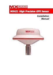
<strong>Manual</strong><br />
MX421<br />
High Precision GPS Sensor<br />
English<br />
Document no: 723594<br />
Revision: E<br />
Date: April 2008<br />
The original language for this document is English. In the<br />
event of any discrepancy between translated versions<br />
and the English version of this document, the English<br />
document will be the official version.<br />
To the best of our knowledge, the content in this<br />
publication was correct at the time of printing.<br />
As we are continuously improving our products we<br />
retain the right to make changes to the product and<br />
the documentation at any time. Updated manuals are<br />
available from our website www.simrad-yachting.com,<br />
and are free to download.<br />
© Copyright 2008 by Navico Holding AS.
2 | MX421<br />
IMPORTANT NOTICE!!<br />
THE MX421 IS AN AID TO NAVIGATION ONLY.<br />
Under no circumstances should it be used in lieu of<br />
authorized government charts. Its accuracy can be<br />
affected by many factors such as equipment defects,<br />
environmental conditions, or improper operation. The<br />
user is responsible for safe navigation of the vessel.<br />
This includes consulting authorized government charts<br />
and exercising common prudence and navigational<br />
judgement at all times.<br />
How to contact us?<br />
Contact your local <strong>SIMRAD</strong> dealer for:<br />
•<br />
•<br />
Installation, Service, & Technical Support<br />
Sales of Accessories<br />
• Hardware and Software Upgrades<br />
Unlike many other consumer electronics industries which<br />
only sell consumer electronic devices, your marine dealer<br />
is often your best advisor for installation and service of<br />
your new GPS receiver. <strong>SIMRAD</strong> strongly encourages you<br />
to utilize the knowledge and experience of your sales and<br />
service dealer.<br />
Should you need to contact us directly for new sales,<br />
upgrades, repair service, or technical support, we can be<br />
reached at the following:<br />
International:<br />
<strong>SIMRAD</strong> (USA)<br />
A Division of NAVICO, Inc.<br />
23868 Hawthorne Blvd., Suite 201<br />
Torrance, California 90505<br />
USA<br />
+1 310 791 8213 (Telephone)<br />
+1 310 791 6108 (Fax)<br />
www.mx-marine.com<br />
In Europe:<br />
Navico UK Ltd<br />
Premier Way, Abbey Park<br />
Romsey, Hampshire<br />
SO51 9DH<br />
United Kingdom<br />
+44 (0)1794 510010 (Telephone)<br />
+44 (0)1794 510006 (Fax)<br />
www.navico.com
Contents<br />
1 Introduction ............................................... 5<br />
2 MX421 Operation ........................................ 7<br />
Receiver Autonomous Integrity Monitoring<br />
(RAIM) ........................................................7<br />
Antenna Connector .......................................8<br />
Supplied Equipment ......................................9<br />
MX421 Mounting Guidelines .......................... 10<br />
3 Installation Procedure .............................. 11<br />
Antenna Mounting ....................................... 11<br />
Power Requirement ..................................... 13<br />
Antenna Cable Assembly .............................. 13<br />
MX421-10 Connector Configuration ................ 15<br />
External Differential Beacon Receiver<br />
Connection ................................................. 15<br />
MX421B-10 Connector Configuration .............. 16<br />
Data Interface to MX420/2 or MK12 CDU ........ 17<br />
Data Interface to MX420/8 or MX420/AIS CDU 18<br />
Data Interface to MX500/510/512 CDU .......... 19<br />
Data Interface to PC or Non-<strong>SIMRAD</strong><br />
Navigation Systems ..................................... 20<br />
4 Specifications ........................................... 21<br />
5 Data Output Protocol ................................ 25<br />
MX421 | 3
4 | MX421<br />
Blank page
1 Introduction<br />
This manual describes the operation and installation of<br />
the MX421 high-precision smart antenna.<br />
The MX421 GPS and DGPS smart antennas were<br />
designed to work with the latest <strong>SIMRAD</strong> Control and<br />
Display Units (MX CDU) or other NMEA 0183 compatible<br />
navigation devices. The MX421 can achieve position<br />
fix accuracies of better than 1 meter with differential<br />
correction or better than 3 meters without correction.<br />
Antenna models covered in this manual are:<br />
MX421-10 - a GPS only smart antenna. This antenna<br />
can accept differential corrections from an external<br />
beacon receiver. A 1-PPS timing output is optionally<br />
available.<br />
MX421B-10 - a combined GPS and Differential beacon<br />
smart antenna. The built-in beacon receiver normally<br />
operates in auto mode when used as a stand-alone<br />
smart antenna. 1 PPS timing output is also optionally<br />
available.<br />
These models use identical housing styles. To determine<br />
the particular model of antenna you have, please check<br />
the model number inscribed on the serial number tag<br />
located at the underside of the antenna housing.<br />
Before installing the MX421, please read this manual<br />
carefully to ensure proper installation and operation of<br />
the unit.<br />
Introduction | 5
6 | Introduction<br />
Blank page
2 MX421 Operation<br />
The MX421-10 and MX421B-10 sensors are highly<br />
integrated GPS and DGPS smart antennas that are fully<br />
automatic and does not require user intervention to<br />
operate in most applications. They will automatically<br />
search for available satellites as soon as power is applied.<br />
It will find its present position as soon as enough satellites<br />
has been acquired and tracked. Typically, it will take about<br />
1 to 2 minutes to find its position when good satellite<br />
ephemeris data is in its memory.<br />
The internal 2-channel beacon receiver in the MX421B-10<br />
continuously monitors all beacon signals available in your<br />
location. The first channel tracks the primary station while<br />
the second channel searches for other available beacons.<br />
Should it find a superior signal it will automatically switch<br />
the primary channel to the new station.<br />
The combined performance of the high-precision<br />
12-channel GPS and 2-channel beacon receivers provide<br />
a more accurate and reliable position fix, usually within 1<br />
meter or less.<br />
The MX421B-10 was designed with an H-Field beacon<br />
antenna for better on-board electrical noise immunity<br />
and requires no grounding.<br />
Receiver Autonomous Integrity<br />
Monitoring (RAIM)<br />
RAIM is a special software algorithm in the MX421<br />
program which gives the operator timely warnings when<br />
the GPS system accuracy is questionable. This feature<br />
requires at least five or more GPS satellites to operate<br />
properly. If the position solution error exceeds 100<br />
meters, a “RAIM Unsafe (R-)” or ”RAIM Caution (R?)<br />
alarm will be indicated in the MX CDU. This means that<br />
the accuracy of the position can not be guaranteed to<br />
be very accurate at that point in time. The operator is<br />
advised to use the GPS cautiously for navigation until<br />
the RAIM indicator switches to (R+) denoting safe RAIM<br />
condition.<br />
Position errors may be caused by unhealthy satellites,<br />
incorrect pseudoranges, poor satellite geometry,<br />
Operation | 7
8 |<br />
8 | Operation<br />
excessive atmospheric interference and problems at<br />
particular reference stations.<br />
Antenna Connector<br />
The 10-pin black plastic connector at the bottom of the<br />
antenna housing provides the necessary interfacing<br />
between the MX421 smart antenna and the <strong>SIMRAD</strong><br />
CDU or other NMEA compatible devices. Below is a table<br />
listing the pin assignments and wire color codes of the<br />
MX421 antenna cable.<br />
Pin # Wire Color MX421-10 MX421B-10<br />
1 BLK Negative Ground<br />
2 RED +9 - 32 VDC<br />
3 BLU MX Proprietary message (MPM) in (-)<br />
4 BRN MX Proprietary message (MPM) in (+)<br />
5 ORG GPS Out (-)<br />
6 GRN GPS Out (+)<br />
7 YEL RTCM in (-) Beacon Status Out (+)<br />
8 WHT RCTM in (+) Beacon Status Out (+)<br />
9 PRPL 1 PPS (+)<br />
10 GRY 1 PPS (-)
Supplied Equipment<br />
The following items are supplied with the MX421<br />
Sensor:<br />
Description Part Number<br />
MX421-10 9525 200 80100<br />
or,<br />
MX421B-10 9525 200 80110<br />
MX421 Installation <strong>Manual</strong> 723594<br />
Figure 1 MX421 Sensor Standard Package<br />
Operation | 9
10 | Operation<br />
MX421 Mounting Guidelines<br />
•<br />
•<br />
•<br />
•<br />
•<br />
•<br />
Install the MX421 antenna where it has a clear view<br />
of the sky around it.<br />
Locate the antenna for easy access and<br />
maintenance.<br />
Locate the antenna at least 10 meters away<br />
from and out of the transmitting beam of radar,<br />
INMARSAT and other high-power transmitters.<br />
Mount the antenna low to avoid excessive position<br />
and speed errors while underway.<br />
Mount the antenna as far away as possible from<br />
large metal structures.<br />
Mount the antenna about 1 meter away from the<br />
compass.<br />
Figure 2 Antenna Location Diagram<br />
If you are not sure if the chosen location is appropriate,<br />
you can mount the antenna temporarily and operate<br />
the unit. Monitor the operation of the MX421 while you<br />
turn on other on-board electronic equipment. Move the<br />
antenna around until the MX421 operates satisfactorily<br />
then mount it permanently.
3 Installation Procedure<br />
Antenna Mounting<br />
Bracket Mount<br />
The MX421 mounting thread is an industry standard<br />
fitting for VHF antenna mounting (1 inch, 14 TPI). This<br />
enables the antenna to be mounted on a wide range of<br />
mounting brackets, including the swivel joints, commonly<br />
used for angled surface.<br />
Hand-tighten the antenna onto the bracket until snug. Do<br />
not overtighten.<br />
Figure 3 MX421 Bracket Mount<br />
Surface Mount<br />
The MX421 may also be surface-mounted. Before making<br />
cuts, verify if there is enough clearance underneath the<br />
mounting surface. A minimum of 5-inch clearance at<br />
the bottom of the antenna is needed to accommodate<br />
the lower section of the MX421 housing, connector and<br />
antenna cable bend see Figure 3.<br />
Installation Procedure | 11
12 | Installation Procedure<br />
Choose a location that has clear view of the sky. Make<br />
sure there are no major obstructions or large metal<br />
fixtures close to the antenna. The GPS antenna relies on<br />
direct ‘line-of-sight’ signal reception. If you are unsure<br />
that the chosen location is suitable, it is advisable<br />
to mount the antenna temporarily and verify proper<br />
operation. Move it around until you are satisfied with the<br />
results.<br />
Refer to Figure below for surface mounting<br />
considerations. Cut a 5 1/4” diameter hole on a<br />
horizontal mounting surface and drill the four mounting<br />
screw holes as shown.<br />
Fasten the antenna by using 2-mm size stainless steel<br />
metric screws (4 places). Use a marine grade caulking<br />
compound to seal between the mounting surface and the<br />
bottom of the antenna housing.<br />
Figure 4 MX421 Surface Mount
Power Requirement<br />
External power supplied to the MX421 must be within<br />
10.5-32 VDC for best operation. To protect the circuitry<br />
in the antenna, the voltage level must be within these<br />
limits. Negative grounding is required. The MX421B-10<br />
draws about 230 mA. at 12 VDC. An in-line fuse or circuit<br />
breaker rated at 2 amp. is recommended for overload<br />
protection.<br />
When the MX421 is connected to a <strong>SIMRAD</strong> control<br />
display console (i.e MX420 or MX500), the antenna power<br />
will be supplied by the display unit.<br />
The RED wire connects to the +12 VDC power, while the<br />
BLACK wire is the negative return. Although the MX421<br />
has a reverse polarity protection, it is prudent to make<br />
sure that proper polarity is observed before making the<br />
connection.<br />
Reverse polarity connection may damage the unit.<br />
Always check polarity before connecting the antenna<br />
cable.<br />
Antenna Cable Assembly<br />
The antenna cable assembly is made up of five shielded<br />
twisted-pair wires and 10-Pin male connector. The<br />
molded connector is pre-installed in the factory. Antenna<br />
cable with two connectors are available for the MX500<br />
CDU model.<br />
The antenna cable run must be surveyed carefully to<br />
determine the appropriate cable length. Wire splicing of<br />
antenna cable should be minimized to prevent signal loss<br />
and potential interference.<br />
The antenna cable assembly is not included in the MX421<br />
package and must be ordered separately. Below are<br />
available lengths in stock:<br />
Installation Procedure| 13
14 | Installation Procedure<br />
Part Number Length<br />
Antenna Cable with One 10-Pin Connector (for all models):<br />
3508 102 70170 20 meter<br />
3508 102 70180 40 meter<br />
3508 102 70640 60 meter<br />
3508 102 70185 80 meter (Special order only)<br />
Antenna Cable with two 10-Pin Connectors (for MX500 <strong>Series</strong>):<br />
500 100 1006 20 meter<br />
500 100 1007 40 meter<br />
Below is a diagram showing the pins and wire colorcoding<br />
of the antenna cable assemblies.<br />
Figure 5 Antenna Cable Assemblies
MX421-10 Connector Configuration<br />
The MX421-10 is GPS only antenna configuration. It<br />
transmits the NMEA data at 4800 baud, 8 bits, 1 stop, no<br />
parity. Figure below shows the MX421-10 connector pin<br />
assignments.<br />
Figure 6 Interface Cable Pin Configuration for MX421-10<br />
Where:<br />
Pins 1 & 2: are used for GND and 12 VDC input.<br />
Pins 3 & 4: <strong>SIMRAD</strong> proprietary message (MPM) input<br />
port.<br />
Pins 5 & 6: GPS output to the MK12, MX420 (CDU) or<br />
other NMEA 183 compatible devices.<br />
Pins 7 & 8: connect to an external beacon receiver like<br />
the <strong>SIMRAD</strong> MX41R.<br />
Pins 9 & 10: 1 PPS output<br />
External Differential Beacon Receiver<br />
Connection<br />
Differential corrections from an external beacon receiver<br />
can be connected to the MX421-10 (GPS only) model.<br />
Connections are done directly to the yellow (Pin 7) and<br />
white (Pin 8) wires of the MX421-10 I/O cable. It will<br />
accept standard RTCM SC-104 signal at 4800 baud.<br />
Installation Procedure | 15
16 | Installation Procedure<br />
MX421B-10 Connector Configuration<br />
The MX421B-10 antenna configuration is a combination<br />
GPS and beacon receiver in one. The built-in differential<br />
receiver operates in auto-search mode in the MX421B-10.<br />
It enhances the accuracy of the GPS receiver to provide<br />
a more accurate position solution. Position accuracy<br />
better than 1 meter is possible with this configuration.<br />
Figure 7 Interface Cable Configuration for MX421B-10<br />
Where:<br />
Pins 1 & 2: are the GND and 12 VDC power input.<br />
Pins 3 & 4: <strong>SIMRAD</strong> proprietary message (MPM) input<br />
port.<br />
Pins 5 & 6: GPS output to the MX420 or other NMEA 0183<br />
compatible devices.<br />
Pins 7 & 8: Beacon monitoring signal output. Sends the<br />
SNR, Signal and Frequency to the <strong>SIMRAD</strong> MX420/8<br />
CDU. Connects to Cable B of the MX420/8 CDU.<br />
Pins 9 & 10: 1 PPS output
Data Interface to MX420/2 or MK12<br />
CDU<br />
Use the diagram below to interface the MX421-10 to a<br />
<strong>SIMRAD</strong> MX420/2 or the MK12 CDU.<br />
Figure 8 MX421-10 Interface to a MX420/2 and MK12 CDUs<br />
Installation Procedure | 17
18 | Installation Procedure<br />
Data Interface to MX420/8 or MX420/<br />
AIS CDU<br />
Use the diagram below to interface the MX421B-10 to a<br />
<strong>SIMRAD</strong> MX420/8 or MX420/AIS CDU.<br />
Figure 9 MX421-10 Interface to MX420/8 or MX420/AIS CDUs
Data Interface to MX500/510/512 CDU<br />
Use the diagram below to interface the MX421 to an MX<br />
500, MX510 or MX512 CDU. Antenna cable assembly<br />
with two 10-Pin connectors are available in 3, 20 and 40<br />
meter lengths.<br />
Figure 10 MX5xx Antenna Interface to MX421<br />
Installation Procedure | 19
20 | Installation Procedure<br />
Data Interface to PC or Non-<strong>SIMRAD</strong><br />
Navigation Systems<br />
Figure below shows the power and data input/output<br />
connections to a PC of other non-<strong>SIMRAD</strong> navigation<br />
systems using a terminal strip and DB9 connector (user<br />
supplied items) to terminate the wires. This configuration<br />
can also be used for uploading the MX421-10 software.<br />
Figure 11 MX421 Interface to a PC chartplotter or Other Non-<br />
<strong>SIMRAD</strong> Navigation Systems
4 Specifications<br />
GPS Receiver<br />
Type: ....... L1, C/A Code (SPS), 12-channel continuous Tracking.<br />
Frequency: .........................................1575.42 MHz (L1 band)<br />
Receiver sensitivity: ....................... -143 dBm Costas threshold<br />
Update rate: ........................................... 1 Hz (5 Hz Optional)<br />
DGPS Input: .......................................... RTCM SC-104 format<br />
Receiver maximum input signal: .................................-10 dBW<br />
Satellite measurement use: ......... 12 channel parallel automatic<br />
selection<br />
Antenna type: ................................................. Ceramic Patch<br />
Maximum navigation dynamics:<br />
Maximum receiver dynamics: ....2125 m.p.h. (950 m/s) 4G (39.2<br />
m/s/s)<br />
Time to first fix:<br />
Cold start (no almanac or other data): ....................120 sec.<br />
Typical, 150 sec 90% probable<br />
Warm start (almanac, last fix-position and time known):<br />
............................... 48 sec (typical), 60 sec 90% probable<br />
Reacquisition time: .............
22 |<br />
22 | Specifications<br />
Beacon Receiver (For MX421B model)<br />
Frequency: ...................283.5 to 325.0 kHz. 2-channel Auto or<br />
<strong>Manual</strong> selection (500 Hz steps)<br />
Minimum Signal: .......................................................15 uV/m<br />
Station Selection: .......Automatic or <strong>Manual</strong> on two independent<br />
receiver channels<br />
Dynamic Range: ......................................................... 90 dB<br />
Adjacent Channel Rejection: ............................ 40 dB (500 Hz)<br />
Channel spacing: ........................................................500 Hz<br />
Frequency offset tolerance: ......................................... + 5 Hz<br />
Antenna type: ........................................................... H-Field<br />
Sensitivity: This is strongly influenced by the atmospheric noise<br />
level. Typically a level of 40 dBuV/m will provide a usable signal<br />
with a 10 dB signal to noise ratio at 200 bps data rate. In very<br />
quite locations and with a data rate of 100 bps, a level of 20<br />
dbuV/m will provide a usable signal.<br />
Input/Output interface: NMEA 0183 signal levels (optically<br />
isolated input) at 4800 baud.<br />
MSK rates: ........... 100 and 200 (automatic or manual selection)<br />
Physical Characteristics<br />
Size:<br />
Height: .................................................3 1/2 in. (89 mm.)<br />
Diameter: ........................................... 7 1/8 in. (182 mm.)<br />
Weigh:<br />
MX421: ..............................1.1 lbs. (500 gm. without cable)<br />
MX421B: 1.9 lbs. (860 gm. without cable) UV stable plastic<br />
radome, waterproof<br />
Mount: ...................................................................1”- 14 tpi<br />
Supply voltage range: ..................................... 10.5 to 32 VDC<br />
Operating current:<br />
MX421: .................................Typically 200 mA at 12.0 VDC<br />
MX421B: ...............................Typically 280 mA at 12.0 VDC<br />
Operating temperature range: ...............-25 to +60 Degrees. C
<strong>SIMRAD</strong> reserves the right to make changes in its<br />
products and specifications without notice.<br />
Specifications | 23
24 | Specifications<br />
Blank page
5 Data Output Protocol<br />
The MX421 GPS and DGPS have been configured in the<br />
factory to output the following NMEA data sentences:<br />
GGA, DTM, GSA, GSV, GST, VTG, RMC, ZDA<br />
NMEA 0183 Data Output Sentences<br />
(1) GGA - Global Positioning System Fix Data<br />
Time, position and fix related data for a GPS receiver.<br />
$GPGGA,hhmmss,llll.llll,a,yyyyy.yyyy,a,x,xx,x.x,x.x,M,x.x,M,x.x,xxxx*hh<br />
1 2 3 4 5 6 7 8 9 10 11 12 13 14<br />
Notes: 1 ----- UTC of position<br />
2,3 --- Latitude - N/S<br />
4,5 --- Longitude - E/W<br />
6 ----- GPS Quality Indicator:<br />
0=Fix not available or invalid<br />
1=GPS SPS Mode, fix valid<br />
2=Differential GPS, SPS Mode, fix valid<br />
3= GPS PPS Mode, fix valid<br />
7 ----- Number of Satellites in use, 00-12, may be<br />
different from the number in view<br />
8 ----- Horizontal Dilution of Precision (HDOP)<br />
9 -----Antenna altitude/mean-sea-level (geoid)<br />
10-----Units of antenna altitude, Meters<br />
11,12-Geoidal Height, Meters<br />
13---- Age of Differential GPS Data<br />
14 ----Differential Reference Station ID<br />
(2) GSA - GPS DOP and Active Satellites<br />
GPS receiver operating mode, satellites used in the<br />
navigation solution reported by the $GPGGA sentence,<br />
and DOP values.<br />
$GPGSA,a,x,xx,xx,xx,xx,xx,xx,xx,xx,xx,xx,xx,xx,x.x,x.x,x.x*hh<br />
1 2 3 4 5 6 7 8 9 10 11 12 13 14 15 16 17<br />
Notes: 1----- Mode: M = <strong>Manual</strong>, forced to operate in 2D<br />
or 3D Mode<br />
A = Automatic, allowed to automatically switch<br />
2D/3D<br />
2 ------ Mode: 1 = Fix not available, 2 = 2D, 3 =<br />
3D<br />
3-14 -- PRN numbers of satellites used in solution<br />
(null for unused fields)<br />
15 ---- PDOP<br />
Data Output Protocol | 25
26 | Data Output Protocol<br />
16 ---- HDOP<br />
17 -----VDOP<br />
(3) GSV - GPS Satellite in View<br />
Number of satellites (SV) in view, PRN numbers,<br />
elevation, azimuth and SNR values. Four satellites<br />
maximum per transmission, additional satellite data sent<br />
in second or third message. Total number of messages<br />
being transmitted and the number of the message<br />
transmitted are indicated in the first two fields.<br />
$GPGSV,x,x,xx,xx,xx,xxx,xx,....................,xx,xx,xxx,xx*hh<br />
1 2 3 4 5 6 7 8 9 10 11 12<br />
Notes: 1 ------Total number of messages, 1 to 3<br />
2 ----- Message number, 1 to 3<br />
3 ----- Total number of satellites in view<br />
4 ----- Satellite PRN number<br />
5 ----- Elevation, degrees, 90 degrees maximum<br />
6 ------Azimuth, degrees True, 000 to 359<br />
7 ------SNR (C/No) 00-99 dB, null when not<br />
tracking<br />
8 ------2nd and 3rd SV<br />
9,10,11,12 - 4th SV<br />
(4) RMC - Recommended Minimum Specific GPS Data<br />
Time, date, position, course and speed data provided by<br />
a GPS navigation receiver. This sentence is transmitted<br />
at intervals not exceeding 2 seconds and is always<br />
accompanied by RMB when a destination waypoint is<br />
active. RMC and RMB are the recommended minimum<br />
data to be provided by a GPS receiver. All data fields<br />
must be provided: null fields used only when data is<br />
temporarily unavailable.<br />
$GPRMC,hhmmss.ss,A,llll.llll,a,yyyyy.yyyy,a,x.x,x.x,xxxxxx,x.x,a*hh<br />
1 2 3 4 5 6 7 8 9 10 11<br />
Notes: 1 ---- UTC of Position fix<br />
2 ---- Status: A = data valid<br />
V = Navigation receiver warning<br />
3,4 -- Latitude, N/S<br />
5,6 -- Longitude, E/W<br />
7 ---- Speed over ground, knots<br />
8 ------ Course Over Ground, True<br />
9 ------ Date: dd/mm/yy<br />
10,11 - Magnetic variation, degrees E/W.<br />
Easterly variation (E) subtracts from True course,<br />
Westerly variation (W) adds to True course.
(6) GST - GNSS Pseudorange Error Statistics<br />
This message is used to support Receiver Autonomous<br />
Integrity Monitoring (RAIM). Pseudorange measurement<br />
error statistics can be translated in the position domain<br />
in order to give statistical measures of the quality of the<br />
position solution.<br />
If only GPS, GLONASS, etc. is used for the reported<br />
position solution, the talker ID is GP, GL, etc., and the<br />
error data pertains to the individual system. If satellites<br />
from multiple systems are used to obtain the reported<br />
position solution, the talker ID is GN and the errors<br />
pertain to the combined solution.<br />
$GPGST,hhmmss.ss,x.x,x.x,x.x,x.x,x.x,x.x,x.x*hh<br />
1 2 3 4 5 6 7 8<br />
Notes: 1 --------- UTC time of the GGA or GNS fix<br />
associated with this sentence.<br />
2 --------- RMS value of the standard deviation of<br />
the range inputs to the navigation process. Range<br />
inputs include preudoranges & DGNSS<br />
corrections.<br />
3 --------- Standard deviation of semi-major axis<br />
of error ellipse (meters)<br />
4 --------- Standard deviation of semi-minor axis<br />
of error ellipse (meters)<br />
5 --------- Orientation of semi-major axis of error<br />
ellipse (degrees from true north)<br />
6 --------- Standard deviation of latitude error<br />
(meters)<br />
7 --------- Standard deviation of longitude error<br />
(meters)<br />
8 --------- Standard deviation of altitude error<br />
(meters)<br />
(7) VTG - Course Over Ground and Ground Speed<br />
The actual course and speed relative to the ground.<br />
$GPVTG,x.x,T,x.x,M,x.x,N,x.x,K,a*hh<br />
1 2 3 4 5 6 7 8 9<br />
Notes: 1,2 ----- Course over ground, degrees True<br />
2,3 ----- Course over ground, degrees Magnetic<br />
5,6 ----- Speed over ground, knots<br />
7,8 ----- Speed over ground, km/hr<br />
Data Output Protocol | 27
28 | Data Output Protocol<br />
9 ------- Mode indicator: A = Autonomous mode<br />
D = Differential mode<br />
E = Estimated (DR)<br />
M = <strong>Manual</strong> input mode<br />
S = Simulator mode<br />
N = Data not valid<br />
(8) ZDA -Time and Date<br />
UTC, day, month, year and local time zone<br />
$GPZDA,hhmmss,xx,xx,xxxx,xx,xx*hh<br />
1 2 3 4 5 6<br />
Notes: 1 --- UTC<br />
2, 3, 4 --- Day, month & year<br />
5 --- Local zone hours, 00 to + 13 hrs.<br />
6 --- Local zone in minutes, 00 to +59.<br />
(9) GBS - GNSS Satellite Fault Detection (Modified<br />
<strong>SIMRAD</strong> version)<br />
This message is used to support Receiver Autonomous<br />
Integrity Monitoring (RAIM) feature in the MX420 CDU. A<br />
special character flag was added for proper RAIM status<br />
determination<br />
$PMVXG,GBS,hhmmss.ss,x.x, x.x,x.x,xx,x.x,x.x,x.x,x*hh<br />
1 2 3 4 5 6 7 8 9<br />
Notes: 1 ----- UTC time of the GGA or GNS fix<br />
associated with this sentence.<br />
2 ----- Expected error in Latitude (meters)<br />
3 ----- Expected error in Longitude (meters)<br />
4 ----- Expected error in Altitude (meters)<br />
5 ----- ID number of most likely failed satellite<br />
6 ----- Probability of missed detection for most<br />
likely failed satellite<br />
7 ----- Estimate of bias in meters on most likely<br />
failed satellite<br />
8 ----- Standard deviation of bias estimate<br />
9 ----- RAIM status mode; 0=safe, 1=caution,<br />
2=unsafe
29 |<br />
Blank page<br />
| 29
30 | How Are We Doing?<br />
How Are We Doing?<br />
Please help us to help you and our other valued<br />
customers by sending us your evaluation of this manual.<br />
We need to know such things as:<br />
•<br />
•<br />
•<br />
•<br />
is the manual complete, or do you need more (or less)<br />
information?<br />
can you find the information you need easily?<br />
is the information easy to understand, or could we be<br />
clearer?<br />
are there any errors and, if so, where and what are they?<br />
Be sure to reference the title and identification number<br />
of this manual:<br />
MX421 Installation <strong>Manual</strong><br />
P/N 723594<br />
and include your name, address and telephone number.<br />
We look forward to finding out how we can improve our<br />
information services.<br />
All of your comments and suggestions become the<br />
property of <strong>SIMRAD</strong>.<br />
Please send them to:<br />
<strong>SIMRAD</strong><br />
A Division of NAVICO, Inc.<br />
23868 Hawthorne Blvd., Suite 201<br />
Torrance, CA 90505<br />
United States of America<br />
or write your comments on the Reader Comment Sheet<br />
on the next page and mail it to us.
Reader Comment Sheet<br />
MX421 Installation <strong>Manual</strong> P/N 723594<br />
<strong>SIMRAD</strong> welcomes your evaluation of this manual. Please<br />
note errors, suggest additions, or make general comments<br />
below. Use extra pages if you like. All comments and suggestions<br />
become the property of <strong>SIMRAD</strong>.<br />
Do not use this form to request purchases, maintenance<br />
assistance, or additional publications. Please contact your<br />
<strong>SIMRAD</strong> marketing representative for purchases or additional<br />
publications, and your nearest authorized service representative<br />
for mainte nance assistance.<br />
Thank you.<br />
______________________________________________<br />
______________________________________________<br />
______________________________________________<br />
______________________________________________<br />
______________________________________________<br />
______________________________________________<br />
______________________________________________<br />
Your Name: ____________________________________<br />
Address:_______________________________________<br />
______________________________________________<br />
Phone: ( )_______________________________<br />
Fold on broken line as shown on other side of page and seal with tape.<br />
MX421 | 31
32 | MX421<br />
<strong>SIMRAD</strong><br />
A Division of NAVICO, Inc.<br />
23868 Hawthorne Blvd., Suite 201<br />
Torrance, CA 90505-5908<br />
USA<br />
Place<br />
Stamp<br />
Here<br />
----------------------------------------------------------------
<strong>Simrad</strong> MX421 High Precision GPS Sensor <strong>Manual</strong> EN, Doc.no. 723594, Rev.E