HOMMEL INCOLINE Dynamic systems for the measurement of ...
HOMMEL INCOLINE Dynamic systems for the measurement of ...
HOMMEL INCOLINE Dynamic systems for the measurement of ...

Create successful ePaper yourself
Turn your PDF publications into a flip-book with our unique Google optimized e-Paper software.
Precision is our business.<strong>HOMMEL</strong> <strong>INCOLINE</strong><strong>Dynamic</strong> <strong>systems</strong> <strong>for</strong> <strong>the</strong><strong>measurement</strong> <strong>of</strong> surfaces and<strong>for</strong>m in <strong>the</strong> developmentand manufacturing <strong>of</strong> enginesJENOPTIK-Group.
V-INCOMETERFlexible measuring system <strong>for</strong> <strong>for</strong>m and roundness in cylinder boresMeasurement and analysis <strong>of</strong>• cylinder distortion• cylinder wear• temperature influence• piston ring dimensioning<strong>for</strong> engine developmentand productionRoundnessStraightnessCylindricityParallelismInner diameterConcentricityV-INCOMETERProbe V-200 with electronics4
V-INCOMETERS<strong>of</strong>tware options <strong>for</strong> research and developmentWear <strong>measurement</strong>This module enables <strong>the</strong> determination<strong>of</strong> cylinder bore wear. The cylinder boreis measured with high precision, wi<strong>the</strong>qually distributed axial scans. Extensivepossibilities <strong>for</strong> <strong>the</strong> presentation <strong>of</strong> <strong>the</strong>measuring results are available.Distortion <strong>measurement</strong> due totemperatureThe INCOMETER requires only a fewminutes to completely measure acylinder bore. This speed <strong>of</strong> operationenables hot engine components (inexcess <strong>of</strong> 100° C) to be measured.The distortion due to temperature can<strong>the</strong>re<strong>for</strong>e be measured, without relyingon simulation methods.Mask-<strong>of</strong>fIt is important to mask-<strong>of</strong>f certain areaswhen measuring and evaluating interruptedsurfaces, as <strong>for</strong> example in case<strong>of</strong> <strong>the</strong> two-stroke engines.Graphical presentation <strong>of</strong> fourier coefficientsFourier coefficientsFourier coefficients in cylinders <strong>of</strong> internalcombustion engines are generallyimportant up to a level <strong>of</strong> 8.To illustrate<strong>the</strong> Fourier coefficients better <strong>the</strong>y canbe presented graphically.Relief map <strong>of</strong> a distorted cylinder liner6
V-INCOMETERS<strong>of</strong>tware options <strong>for</strong> manufacturingData transmission to QS-STATThis s<strong>of</strong>tware package creates files fromstandard results which can be processedby <strong>the</strong> SPC package QS-STAT“. The<strong>measurement</strong> files can be read by o<strong>the</strong>rexternal packages <strong>for</strong> subsequent statisticalevaluation.Complete <strong>measurement</strong> and evaluationOnce all <strong>the</strong> specification data has beenentered into <strong>the</strong> s<strong>of</strong>tware, it will enable<strong>the</strong> <strong>measurement</strong> <strong>of</strong> a complete crankcase.The s<strong>of</strong>tware guides <strong>the</strong> operatorthrough <strong>the</strong> measuring procedure. All<strong>the</strong> <strong>measurement</strong>s <strong>for</strong> each cylinder arestored in a single file. Evaluation optionsinclude <strong>the</strong> display <strong>of</strong> <strong>the</strong> <strong>for</strong>m <strong>of</strong> eachcylinder in a tabular <strong>for</strong>mat and also asradial, axial and isometric plots. Multipleplots can be displayed on one page,which can be preset by <strong>the</strong> operator.Complete evaluation <strong>of</strong> a motor unitMeasuring <strong>the</strong> absolute diameterThis s<strong>of</strong>tware extension permits <strong>the</strong><strong>measurement</strong> <strong>of</strong> <strong>the</strong> absolute diameter<strong>of</strong> <strong>the</strong> cylinders in <strong>the</strong> crankcase. Be<strong>for</strong>eeach <strong>measurement</strong> <strong>the</strong> INCOMETER iscalibrated to <strong>the</strong> nominal dimension <strong>of</strong><strong>the</strong> cylinder diameter. This calibration isper<strong>for</strong>med in a special fixture equippedei<strong>the</strong>r with integrated calibration ringsor with a fixture plate with built-incalibration rings to be mounted on <strong>the</strong>cylinder head gasket. A third possibilityis to manufacture a calibration cylinderwith <strong>the</strong> nominal dimensions <strong>of</strong> <strong>the</strong>cylinder bore.All measuring results at a glance7
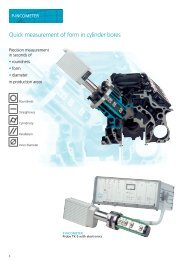
P-INCOMETERQuick <strong>measurement</strong> <strong>of</strong> <strong>for</strong>m in cylinder boresPrecision <strong>measurement</strong>in seconds <strong>of</strong>• roundness• <strong>for</strong>m• diameterin production areasRoundnessStraightnessCylindricityParallelismInner diameterP-INCOMETERProbe TK-5 with electronics8
P-INCOMETERP-INCOMETER by <strong>HOMMEL</strong> INCOTECQuick and reliable generation <strong>of</strong> cylinderbore data accurate to microns, directlyin <strong>the</strong> production area.Rugged and highly preciseThe P-INCOMETER was conceptualizedafter <strong>the</strong> long established V-INCOMETERin order to utilize proven technical features,i.e. <strong>the</strong> connection <strong>of</strong> <strong>the</strong> measuringhead to <strong>the</strong> engine block to safeguardagainst vibration. Also, <strong>the</strong> “selfadjusting”principle is integrated so that<strong>the</strong> manual adjustment <strong>of</strong> <strong>the</strong> probe to<strong>the</strong> bore is not necessary.These fundamental features give <strong>the</strong>system high accuracy even in harsh productionenvironments.High flexibilityThe modular design <strong>of</strong> <strong>the</strong> measuringprobe enables quick and simple adaptationto different bore sizes. By simplyexchanging <strong>the</strong> measuring head andfixing plates, different engines can bemeasured without <strong>the</strong> need <strong>for</strong> specialinstallation tools. The measuring headis equipped with up to 7 sensors positionedaccording to customers specifications.Simple operationThe s<strong>of</strong>tware package runs on standardsystem PCs. Clearly structured menusand automatic measuring and evaluationsequences enable easy, error-freeoperation without requiring extensivetraining. Measurement results are automaticallyprinted at <strong>the</strong> end <strong>of</strong> eachcycle.Mobile useDue to <strong>the</strong> small size and light weight<strong>of</strong> <strong>the</strong> P-INCOMETER, <strong>the</strong> system isideal <strong>for</strong> use on different productionlines around <strong>the</strong> plant.Easy handlingTo take a <strong>measurement</strong> <strong>the</strong> P-INCO-METER is inserted into <strong>the</strong> cylinder bore.Plastic guide rails are integrated into<strong>the</strong> measuring head to avoid damage to<strong>the</strong> cylinder wall. A centering collar on<strong>the</strong> P-Incometer unit and a fixture platemounted on <strong>the</strong> engine block are coupledtoge<strong>the</strong>r by <strong>the</strong> use <strong>of</strong> a clampinglever. This ensures that <strong>the</strong> P-INCOME-TER is in <strong>the</strong> correct measuring positionon <strong>the</strong> engine block.After starting a <strong>measurement</strong>, <strong>the</strong> measuringhead begins a scanning rotation<strong>of</strong> 360°. Measurement values from eachsensor are taken simultaneously at aconstant speed. After <strong>the</strong> <strong>measurement</strong>,which only takes a few seconds, <strong>the</strong> calculationsare computed and <strong>the</strong> resultsare printed.Inserting <strong>of</strong> <strong>the</strong> probeFixing <strong>of</strong> <strong>the</strong> probePROTOKOLL EINER ZYLINDERMESSUNGROUNDNESS (0....6 µm)Level 1, 10 mm : 5.8 µm I------------------x-ILevel 2, 30 mm : 4.4 µm I-------------x------ILevel 3, 50 mm : 4.3 µm I------------x-------ILevel 4, 70 mm : 4.2 µm I------------x-------ILevel 5, 90 mm : 5.1 µm I----------------x---ISTRAIGHTNESS (0....6 µm)Angle 0° : 2.3 µm I-------x------------IAngle 90° : 5.5 µm I-----------------x--IAngle 180° : 1.7 µm I-----x--------------IAngle 270° : 4.9 µm I---------------x----IPARALLELISM (0....12 µm)Angle 0 / 180° : 8.8 µm I-------------x------IAngle 90 / 270° : 13.5 µm I--------------------IxCYLINDER FORM (0....12 µm): 11.9 µm I-------------------xIAxial plot <strong>of</strong> acylinder boreRadial plot <strong>of</strong>chosen levelsIsometric plot <strong>of</strong>cylinder bore9
MULTI-INCOMETERForm measuring system <strong>for</strong> crank- and camshaft bearingsMeasurement and analysis <strong>of</strong>• roundness• <strong>for</strong>m• alignment<strong>of</strong> parallel bores andbearings in developmentand production areasRoundnessStraightnessCylindricityParallelismInner diameterConcentricityMULTI-INCOMETER by <strong>HOMMEL</strong> INCOTECQuick and reliable documentation<strong>of</strong> roundness, <strong>for</strong>m and alignment <strong>of</strong>parallel bores and bearings in developmentand production areas.Economical <strong>measurement</strong>Unlike conventional <strong>for</strong>m <strong>measurement</strong>machines, <strong>the</strong> size <strong>of</strong> this machine isnot determined by <strong>the</strong> object to bemeasured. Thanks to <strong>the</strong> design <strong>of</strong> <strong>the</strong>MULTI-INCOMETER with exchangeablemeasuring heads and/or measuringshafts, simple adaptation <strong>of</strong> <strong>the</strong> probeto different engine block dimensionsis made possible. The simultaneous<strong>measurement</strong> <strong>of</strong> up to eight measuringlocations allow <strong>for</strong> shortened measuringtimes. The s<strong>of</strong>tware activates appropriatecontrol and evaluation programs,eliminating time consuming programming.The results are available immediatelyafter <strong>the</strong> <strong>measurement</strong>, <strong>the</strong>re<strong>for</strong>eenabling quick, on-site analysis.MULTI-INCOMETERProbe M-750 with electronics10
MULTI-INCOMETERHigh flexibilityDue to <strong>the</strong> modular design wi<strong>the</strong>xchangeable measuring shafts andadjustable measuring heads varioustypes <strong>of</strong> objects can be inspected(i.e. crankshaft and camshaft bearings,gear boxes, etc.).Simple operation and handlingThe probe is inserted into <strong>the</strong> nearingline, mounted on <strong>the</strong> drive side and <strong>the</strong>shaft end and fixed within <strong>the</strong> object tobe measured. This installation is donewith simple, appropriately adaptedflanges. These flanges are pre-alignedand fixed to <strong>the</strong> object with a centeringunit be<strong>for</strong>e <strong>the</strong> probe is inserted. Forproduction areas where different <strong>measurement</strong>sare frequently taken, fixturesare used which do not require pre-centering.This makes it possible to start a<strong>measurement</strong> immediately after inserting<strong>the</strong> probe. Through use <strong>of</strong> <strong>the</strong> functionkeys, <strong>the</strong> connected computer and<strong>the</strong> clear menu-guided s<strong>of</strong>tware, <strong>the</strong>MULTI-INCOMETER measuring systemcan be operated without extensive training.Mobile useThe MULTI-INCOMETER system is quicklyready <strong>for</strong> use and <strong>measurement</strong>. It isespecially well-suited <strong>for</strong> on-site <strong>measurement</strong>sbecause <strong>of</strong> its small dimensionsand portability. This makes <strong>the</strong>MULTI-INCOMETER very practical <strong>for</strong> usein different areas such as development,laboratory, inspection and also in production.Measurement <strong>of</strong> crankshaft bearingsFixture <strong>for</strong> cylinder headMounting device <strong>for</strong> <strong>the</strong>crankshaft bearing line.Measurement directly afterinserting <strong>the</strong> probe into<strong>the</strong> engine block withoutpre-alignment11
MULTI-INCOMETERIsometric display <strong>of</strong> a bearing location Axial plot Radial plotOffset between bearing shells Center points <strong>of</strong> bearings Offset bearing to bearing shellsHole masking Isometric display <strong>of</strong> <strong>the</strong> bearing channel Overview <strong>of</strong> crankshaft bearings13
VS-INCOMETERForm measuring system <strong>for</strong> small cylinder boresMeasuring <strong>of</strong>• Cylinder distortion• Cylinder wear• Influence <strong>of</strong> temperature• Dimensions <strong>of</strong> piston ringsIn <strong>the</strong> development andmanufacture <strong>of</strong> enginesRoundnessStraightnessCylinder <strong>for</strong>mParallelismInterior diameterConcentricityVS-INCOMETER from <strong>HOMMEL</strong> INCOTECA Rapid and reliable measuringsystem with maximum precision <strong>for</strong>detailed testing <strong>of</strong> cylinder bores onsmall engines.Special advantagesThe VS-INCOMETER has been developedfrom <strong>the</strong> worldwide renowned V-INCO-METER. The large range <strong>of</strong> diametersfrom 39-100 mm enables its usein many different engine types. The<strong>measurement</strong> method scans with up to4095 data points per revolution and upto 100 levels. This method reduces <strong>the</strong>total measuring time to an absoluteminimum. This fact and <strong>the</strong> automaticadjustment <strong>of</strong> inclination and eccentricity<strong>of</strong> <strong>the</strong> sensor relative to <strong>the</strong> bore areunique.ApplicationsThe VS-INCOMETER has been speciallydesigned <strong>for</strong> <strong>the</strong> <strong>measurement</strong> andanalyse <strong>of</strong> cylinder distortions <strong>of</strong> smalldiesel engines, toge<strong>the</strong>r with two-strokeand four-stroke engines. These enginesare used mainly in small agricultural and<strong>for</strong>estry appliances. The system is predominatelyused in measuring rooms <strong>for</strong>research and development, though <strong>the</strong>robust and compact design also enablesits use on <strong>the</strong> shop floor.Simple and rapid useThe adaptation and programming <strong>of</strong> <strong>the</strong>system is through a menu in order tominimise operator training and enableits simple and effective use. The transmission<strong>of</strong> all <strong>measurement</strong> data to acentral computer enables external evaluationsand SPC analysis.AbstractThe use <strong>of</strong> this special measuring systemis <strong>of</strong> major benefit to <strong>the</strong> manufacturer<strong>of</strong> engines, considering <strong>the</strong> strict regulationsregarding fuel consumption,higher power and lower emissions.The investment in an Incometer systemwill quickly repay itself.Isometric Form with 40 levelsIsometric Form with automaticmasking-<strong>of</strong>f14
MINI-INCOMETERForm measuring system <strong>for</strong> internal andexternal contoursMeasuring <strong>of</strong>• Cylinder distortion• Cylinder wear• Temperature influence• Piston ring dimensionIn <strong>the</strong> development andmanufacture <strong>of</strong> enginesRoundnessStraightnessCylinder <strong>for</strong>mIsometry <strong>of</strong> two bearing shellsParallelismAlignment <strong>of</strong> two bearingsInterior diameterConcentricityMINI-INCOMETER from <strong>HOMMEL</strong>INCOTECRapid, reliable and highly precise <strong>measurement</strong><strong>for</strong> <strong>the</strong> analysis <strong>of</strong> small boresand shafts.Flexible and mobileDue to its simple operation <strong>the</strong>INCOMETER can be adapted to suitdifferent diameters within seconds.This meets one <strong>of</strong> <strong>the</strong> main requirements<strong>for</strong> <strong>the</strong> use in development andtesting departments .Due to its light weight and compactdesign <strong>the</strong> INCOMETER can be easilyused in many different areas within <strong>the</strong>shop floor.Simple handlingThe system can be operated with ease,using <strong>the</strong> function keys <strong>of</strong> <strong>the</strong> controland evaluation unit and <strong>the</strong> clear userinterface. The measured values can beused <strong>for</strong> determining <strong>the</strong> <strong>for</strong>m <strong>of</strong> smallbores and shafts. The measuring sensorhas <strong>the</strong> same advantages as all devices<strong>of</strong> <strong>the</strong> INCOMETER family: high precision,rapid and flexible use and extensiveprograms <strong>for</strong> command, adjustmentand evaluation <strong>of</strong> measured data.ApplicationThe MINI-INCOMETER is used worldwideespecially in <strong>the</strong> area <strong>of</strong> enginedevelopment and experimental manufacturing.The system is particularly useful<strong>for</strong> <strong>the</strong> <strong>measurement</strong> <strong>of</strong> bearingswith small diameters in previously inaccessibleplaces.A special application <strong>of</strong> <strong>the</strong> MINI-INCOMETER is <strong>the</strong> measuring <strong>of</strong> pistonpin bosses relating to <strong>for</strong>m, alignmentand <strong>the</strong> precise <strong>measurement</strong> <strong>of</strong> smallshafts in <strong>the</strong> mm area or <strong>the</strong> <strong>measurement</strong><strong>of</strong> external or internal contours.15
TOPOMETERSurface inspection system <strong>for</strong> cylinder boresMeasurement and assessment<strong>of</strong> surface features as• Crosshatch-angles• Dimension <strong>of</strong>surface structure• Area <strong>of</strong> blowholes• Stroke reversal radius• Roughness<strong>of</strong> cylinder bores indevelopment, resarchand production areasTOPOMETER by <strong>HOMMEL</strong> INCOTECQuick and accurate inspection <strong>of</strong> cylinderbore surfaces directly on <strong>the</strong> productionfloor. Visual inspection <strong>of</strong> surfacefeatures and contact inspection <strong>of</strong> surfacefinish are uniquely combined in onecompact measuring probe.Highly flexibleThe TOPOMETER inspection unit isavailable in two versions. A base modelserving solely as a visual inspection unit,and an extended model combined withroughness measuring capabilities. Visualkits can be upgraded or retr<strong>of</strong>it to fullfeature models. The probes are availablein operating lengths <strong>of</strong> 100 mm –200 mm and can be used in bores all<strong>the</strong> way down to 60mm in diameter.Different bore diameters are adaptedby simply exchanging <strong>the</strong> locators used<strong>for</strong> radial pivoting and centering <strong>of</strong> <strong>the</strong>probe.Easy handlingThe entire system control is centrallylocated in <strong>the</strong> compact industrial PCwith extension boards <strong>for</strong> live video display,image processing and <strong>the</strong> roughnesstesting unit. The <strong>systems</strong> s<strong>of</strong>twaremenus are clearly structured and guide<strong>the</strong> operator through <strong>the</strong> individualsteps <strong>of</strong> operation. The s<strong>of</strong>tware is operatedusing <strong>the</strong> keyboard function keys,<strong>the</strong> mouse, or <strong>the</strong> track ball. In addition,<strong>the</strong> functions needed most frequentlyduring operation, such as motorizedaxial positioning, motorized zoomadjustment and illumination adjustmentare ergonomically located directly on<strong>the</strong> probe itself. Within seconds <strong>of</strong>inserting <strong>the</strong> high resolution opticalprobe in <strong>the</strong> cylinder bore, <strong>the</strong> inspectorsees a magnified image <strong>of</strong> <strong>the</strong> surfaceon <strong>the</strong> PC system.Complete bore assessmentThe system enables <strong>the</strong> complete assessment<strong>of</strong> <strong>the</strong> inspected cylinder bore.This complete assessment includes fastaxial scanning, a full range <strong>of</strong> possiblevisual <strong>measurement</strong>s at any locationwithin <strong>the</strong> bore and <strong>the</strong> capability toevaluate <strong>the</strong>se areas within <strong>the</strong> bore interms <strong>of</strong> all standard DIN and ISOroughness parameters. The individual,adjustable light sources enable optimumillumination <strong>of</strong> any particular bore surfaceto be measured.16
TOPOMETERWide range <strong>of</strong> functionsThe user-friendly menus allow <strong>the</strong>inspectior to quickly measure <strong>the</strong> crosshatchpattern, including angles indegrees, grooves width or o<strong>the</strong>r dimensionsin inch or metric, areas <strong>of</strong> defectsand stroke reversal radius. An easyto-usecontrol panel lets <strong>the</strong> inspectorselect <strong>the</strong> measuring mode and complete<strong>the</strong> measuring in a matter <strong>of</strong>seconds. The data is displayed on <strong>the</strong>screen in <strong>the</strong> desired unit.High sampling ratesFor rapid angular check, a tolerancemode overlays a “reference” angle in<strong>the</strong> middle <strong>of</strong> <strong>the</strong> screen with angularlimits set to correspond with <strong>the</strong> specifiedtolerances selected. The operatorpositions <strong>the</strong> tolerance image over <strong>the</strong>cross-hatch angle to be checked andvisually verifies <strong>the</strong> fit.Documentation guaranteedThe optical video printer supplies immediatehard copy photographic documentation<strong>of</strong> <strong>the</strong> image and data on <strong>the</strong>video screen. A laser-printer can beconnected <strong>for</strong> numerical and graphicalprintouts <strong>of</strong> <strong>the</strong> roughness parametersand pr<strong>of</strong>iles. Optical discs are available<strong>for</strong> video image storing and archiving.Mobile useDue to <strong>the</strong> compact design and <strong>the</strong> lowweight <strong>of</strong> <strong>the</strong> probe <strong>of</strong> <strong>the</strong> measuringsystem can be com<strong>for</strong>tably moved todifferent locations throughout <strong>the</strong> plantfloor.TOPOMETER by <strong>HOMMEL</strong> INCOTECThe ideal inspection unit <strong>for</strong> quick andaccurate inspection <strong>of</strong> cylinder boresdirectly in production areas.Evaluation <strong>of</strong> <strong>the</strong> cross-hatch anglesDisplay <strong>of</strong> a bore surfaceIndustrial housing <strong>for</strong> use in productionenvironmentsDisplay <strong>of</strong> roughness pr<strong>of</strong>iles17
SAMSAM – Semi-automatic measuring systemPrecision <strong>measurement</strong> <strong>of</strong>• roundness and <strong>for</strong>m• surface structure• roughness<strong>of</strong> cylinder boresin production areasSAM by <strong>HOMMEL</strong> INCOTECQuick generation <strong>of</strong> data directly in <strong>the</strong>production area.Rugged and highly preciseFor <strong>measurement</strong> in production areas,high demands are made on <strong>the</strong> designintegrity, especially on <strong>the</strong> measuringprobes used. By <strong>the</strong> use <strong>of</strong> provenrugged, standard measuring probes i.e.<strong>the</strong> INCOMETER MR100 with its selfadjustingprinciple, high accuracies areguaranteed even in harsh productionenvironments.High flexibilityThe modular design <strong>of</strong> <strong>the</strong> SAM enableseasy adaptation <strong>for</strong> different measuringtasks. This is achieved by <strong>the</strong> combination<strong>of</strong> different measuring probes.An additional extension <strong>for</strong> o<strong>the</strong>r measuringprobes is possible is possible<strong>for</strong> more measuring applications. Dueto <strong>the</strong> integrated NC-axis varying borepitches can be handled on one machine.Compact designThe measuring machine type SAM isbuild using aluminium pr<strong>of</strong>iles. Thesturdy carriers <strong>of</strong> <strong>the</strong> machine base areset on <strong>the</strong> floor with vibration padsremoving frequencies from surroundingmachinery.The riser assembly <strong>for</strong> <strong>the</strong> measuringprobes mounted to <strong>the</strong> machine base,is build <strong>of</strong> pr<strong>of</strong>iles with foamed coresand is additionally supported by diagonalstruts. This makes <strong>the</strong> assemblyextremely stiff and insensitive to externalvibrations.Simple operationExternal function keys and a clear structuredcontrol s<strong>of</strong>tware guarantee <strong>the</strong>simple operation <strong>of</strong> <strong>the</strong> system withouta great deal <strong>of</strong> training. The machinerequires only one terminal <strong>for</strong> <strong>the</strong> entiresystem control and evaluation. The fullyautomatic measuring sequence relievespersonnel operation.18
SAMAutomatic measuring sequenceAfter <strong>the</strong> loading <strong>of</strong> <strong>the</strong> SAM and starting<strong>the</strong> measuring cycle, <strong>the</strong> engineblock is positioned below <strong>the</strong> probesand <strong>the</strong> bores are measured sequentially.Upon completion <strong>of</strong> <strong>the</strong> <strong>measurement</strong><strong>the</strong> engine block is automaticallytransferred back to <strong>the</strong> loading position.Modern control designBy <strong>the</strong> combination <strong>of</strong> an IBM-compatiblework station with a fieldbus system,<strong>the</strong> control signals and <strong>the</strong> measureddata are transferred and calculatedtoge<strong>the</strong>r so that short measuring timesare achieved. The whole electrical section<strong>of</strong> <strong>the</strong> machine, including controland evaluation computer, is installedin a double cabinet. All standard safetyprocedures are considered in <strong>the</strong>mechanical and electrical design. Thedesign enables a simple diagnosticsand repair in <strong>the</strong> case <strong>of</strong> a breakdown.SAM by <strong>HOMMEL</strong> INCOTECOffers <strong>the</strong> possibility to monitor <strong>the</strong>quality <strong>of</strong> <strong>the</strong> production process with<strong>the</strong> accuracy <strong>of</strong> laboratory equipment.Quality control can be achieved directlyat <strong>the</strong> production line.Probe MR 100Roundnessand <strong>for</strong>m– Roundness– Straightness– Cylindricity– Parallelism– Inner diameterProbe H 100Surface finish– Stucture–Cross-hatchangle–Width <strong>of</strong>grooves– Hone qualityProbe R 100Roughness– Depth <strong>of</strong>roughness–Average roughnessvalue–Average peakto valley hight–Mean peakhight19
VMMMeasuring system <strong>for</strong> valve guide and valve seatMeasuring system <strong>for</strong>valve guide and valve seat• Roundness• Form• Run-out• Angle• Width<strong>of</strong> valve guide and seatRoundnessCylindricityRun-outDiameterStraightnessParallelismSeatangleSeat width20
VMMVALVE guide / seat measuring station by<strong>HOMMEL</strong> INCOTECQuality data <strong>for</strong> roundness, <strong>for</strong>m,run-out, angle and width directly in <strong>the</strong>production area.Highly precise and ruggedFor <strong>measurement</strong> in production areas,high demands are made on designintegrity. By <strong>the</strong> use <strong>of</strong> proven ruggedstandard <strong>measurement</strong> probes, i.e. <strong>the</strong>INCOMETER MV 100, accuracies within1 micron are guaranteed even in harshproduction environments.High flexibilityThe modular design <strong>of</strong> <strong>the</strong> measuringhead enables easy set-up to differentgeometric configurations, e.g. differentvalve seat diameter ranges <strong>for</strong> intakeand exhaust ports. Different head typescan be measured on one machine bychanging fixture plates and choosing<strong>the</strong> appropriate s<strong>of</strong>tware programs.Compact designThe measuring station is built usingsturdy aluminium pr<strong>of</strong>iles. The station ismounted on anti-vibration pads to eliminatelow frequencies from surroundingmachinery. The complete electricalsection <strong>of</strong> <strong>the</strong> machine, including <strong>the</strong>PC-based control, evaluation computerand EC 110 electronics unit is integratedinto <strong>the</strong> base machine. All standardsafety procedures are considered in <strong>the</strong>electrical and mechanical design. Thisdesign facilitates simple diagnosis andrepair in <strong>the</strong> event <strong>of</strong> a breakdown.Simple operationDue to <strong>the</strong> <strong>systems</strong> automatic valverecognition, operator errors are reducedto a minimum. The clearly structureds<strong>of</strong>tware guarantees <strong>the</strong> simple operation<strong>of</strong> <strong>the</strong> system without a great deal<strong>of</strong> training. The entire system controland evaluation is operated through <strong>the</strong>PC-keyboard.Automatic <strong>measurement</strong> sequenceAfter manually loading and located <strong>the</strong>cylinder head onto <strong>the</strong> fixture and positioningit into <strong>the</strong> measuring location,<strong>the</strong> operator begins <strong>the</strong> automatic measuringsequence <strong>for</strong> <strong>the</strong> relevant guide /seat.The system <strong>the</strong>n automatically correctsany inherent misalignment <strong>of</strong> <strong>the</strong> measuringprobe to <strong>the</strong> guide / seat using<strong>the</strong> x-y compensation unit required,and <strong>the</strong>n completes <strong>the</strong> <strong>measurement</strong>sequence. Upon completion, <strong>the</strong> nextvalve location is positioned and <strong>the</strong>measuring cycle re-started. Fully automaticversions with automated partmovement reduce <strong>the</strong> operator handlingto loading and unloading.Valve guide / seat measuring station by<strong>HOMMEL</strong> INCOTECThe measuring station by <strong>HOMMEL</strong>INCOTEC <strong>of</strong>fers <strong>the</strong> possibility to monitor<strong>the</strong> quality <strong>of</strong> production procedureswith <strong>the</strong> accuracy <strong>of</strong> laboratory equipment.Quality control can now beachieved directly on <strong>the</strong> production line.Measuring sensor in contact with valveguide and seaty-z compensation unit with tiltingunitMeasuring head21
INCOWINWindows control and evaluation s<strong>of</strong>tware <strong>for</strong> INCOMETER• Scanning <strong>measurement</strong>sas a standard feature• Upgrade capability <strong>for</strong>earlier <strong>systems</strong>• Multi-tasking Windowsapplication• Rapid setup <strong>of</strong> allcustomer specificrequirements• Optimum systemportability withnotebook PCClearly arranged out desktop with 100% context sensitive online help functionINCOWINThe new Windows s<strong>of</strong>tware, INCOWIN,enables <strong>the</strong> usage <strong>of</strong> <strong>the</strong> V-INCOMETERsystem with latest operating <strong>systems</strong>such as Windows NT, Windows 2000and Windows XP. The intuitive operation<strong>of</strong> <strong>the</strong> measuring system, straight<strong>for</strong>ward editing <strong>of</strong> new <strong>measurement</strong>protocols and <strong>the</strong> networking capability<strong>for</strong> centralized data storage are justsome <strong>of</strong> <strong>the</strong>se advantages.Multi-TaskingA new interface board has been developedto handle timing critical functions.The entire logic is generated in <strong>the</strong>microprocessor based INCO2 interfaceboard, which is integrated in <strong>the</strong> EC110electronics unit. The connectionbetween <strong>the</strong> PC and <strong>the</strong> electronicsunit is merely a standard interface cable.This feature enables <strong>the</strong> operation <strong>of</strong><strong>the</strong> INCOMETER system with a notebookPC creating a new dimension <strong>of</strong>portability.22
INCOWIN<strong>Dynamic</strong> <strong>measurement</strong>The Windows based system nowincludes high resolution scanning capability.The standard <strong>measurement</strong> <strong>of</strong>cylinder bores is done with a high resolutionscanning and evaluation <strong>of</strong> eachlevel with 14400 steps/1024 points perlevel. Axial <strong>measurement</strong>s are carriedthrough as scans with <strong>the</strong> max. possiblesteps <strong>of</strong> 600 measured points per millimeter.The greatest advantage <strong>of</strong> this newscanning capability is <strong>the</strong> high resolutionrepresentation <strong>of</strong> <strong>the</strong> actual boregeometry reflecting <strong>the</strong> true quality <strong>of</strong>manufacturing precision. The higherdata density allows <strong>for</strong> <strong>the</strong> use <strong>of</strong> standardfiltering routines with a wide range<strong>of</strong> settings. Fourier, gaussian and medianfilters with settings from 0–500 uprare possible.Additionally this advanced „continuousscanning” operation reduces <strong>the</strong> actualmeasuring time to approx. 8 secondsper level regardless <strong>of</strong> <strong>the</strong> number <strong>of</strong>points (24, 72, 144, 180, 360, 720 or1024) chosen <strong>for</strong> <strong>the</strong> final evaluation.UpgradeThe described changes require certainhardware pre-requisits. Due to this anupgrade <strong>of</strong> <strong>the</strong> system to <strong>the</strong> new Windowscontrol and evaluation s<strong>of</strong>twaremay require different degrees <strong>of</strong> alterationsdepending on <strong>the</strong> age andaccordingly <strong>the</strong> technological status <strong>of</strong><strong>the</strong> system.Older <strong>systems</strong> that still operate with <strong>the</strong>electronics unit type EC100M are nei<strong>the</strong>rcapable to operate in <strong>the</strong> high resolutionscanning method nor functionablewith <strong>the</strong> new INCOWIN s<strong>of</strong>tware.There<strong>for</strong>e, <strong>the</strong>y will need to be convertedto <strong>the</strong> electronics unit type EC110.The communication between <strong>the</strong> PCand <strong>the</strong> electronics unit is carriedthrough by a standard serial interface inconjunction with <strong>the</strong> new INCO2 interfaceboard which replaces <strong>the</strong> previousinterface.Customized print layoutsNumerous support tools23
INCOMETERProduct familyINCOMETER familyThe modular structure <strong>of</strong> <strong>the</strong> measuring<strong>systems</strong> permits <strong>the</strong> operation <strong>of</strong> differentmeasuring sensors with one singleelectronic and computer unit. This savesmoney and increases <strong>the</strong> mobility <strong>of</strong> <strong>the</strong><strong>systems</strong>.FORM MEASUREMENTV-INCOMETERMini-INCOMETERV 80 V 115 V 150 V 200 K 100Diameter <strong>of</strong> <strong>the</strong> cylinder * 65 – 155 mm 16 – 65 mmClamping length min. 20 mm 20 mm 25 mm 30 mmAxial measuring range 80 mm 115 mm 150 mm 200 mm 100 mmMeasuring path on <strong>the</strong> circumferenceRadial measuring range ± 400 µm ± 700 µmResolutionNumber <strong>of</strong> measured values per rotation 14.400 / 1.024 4.096Number <strong>of</strong> sensors 1 1Repeating accuracyRoundness ≤ 1,0 µm ≤ 1,0 µmCylinder <strong>for</strong>m ≤ 1,5 µm ≤ 1,5 µmParallelism ≤ 1,5 µm ≤ 1,5 µmMeasuring accuracyRoundness ≤ 1,0 µm ≤ 2,0 µmCylinder <strong>for</strong>m ≤ 1,5 µm ≤ 2,0 µmParallelism ≤ 1,5 µm ≤ 2,0 µmTemperature range <strong>of</strong> use **Power supplyPower consumption 150 W 150 WWeight <strong>of</strong> <strong>the</strong> sensor 2,9 kg 2,5 kg* Fur<strong>the</strong>r diameters on demand **Measuring <strong>of</strong> <strong>the</strong> warm distortion on demand ***Dependant on <strong>the</strong> diameter24
TECHNICAL DATAProduct rangeDimensions in mmØ min/max Height/Depth Width <strong>of</strong> parts Length <strong>of</strong> parts Weight Laboratory <strong>of</strong>f-linewith INCOTEC products ≤ ≤ ≤ ≤ ≤Cylinder bore 36 – 350 500 500 700 60 VS-INCOMETER P-INCOMETERV-INCOMETERSAMMAXI-INCOMETERCylinder liners 30 – 350 600 Ø 320 620 30 VS-INCOMETER P-INCOMETERV-INCOMETERSAMMAXI-INCOMETERCamshaft bearing bore 22 – 100 60 325 600 30 MULTI -(MINI)- MULTI -(MINI)-INCOMETER V-INCOMETERCrankshaft bearing 50 – 120 60 500 700 60 MULTI (MINI) MULTI (MINI)INCOMETER INCOMETERValve guide bore 5 – 10 50 325 600 30 VMM VMMValve seat 25 – 45 2,5 325 600 30 VMM VMMVS-INCOMETER Maxi-INCOMETER Multi-INCOMETER Multi-Mini-INCOMETER P-INCOMETER SAMVS 100 L 275 L 400 M 600 M 750 M 1000 C 500 P 100 MR 10039 – 100 mm 110 – 305 mm 50 – 75 mm 55 – 85 mm 60 – 100 mm 22 – 55 mm 60 – 110 mm 65 – 150 mmext. fixture100 mm 275 mm 400 mm 60 mm 60 mm max. 300 mm max. 300 mm360°± 500 µm ± 700 µm ± 700 µm ± 700 µm ***± 500 / 1000 µm ± 1000 µm0,1 µm4.096 4.096 4.096 4.096 14.400 / 1.024 14.400 / 1.0241 1 max. 8 max. 8 max. 7 max. 8≤ 1,0 µm ≤ 1,0 µm ≤ 1,5 µm ≤ 1,0 µm ≤ 1,0 µm ≤ 1,0 µm ≤ 1,0 µm≤ 1,5 µm ≤ 1,5 µm ≤ 1,5 µm ≤ 1,5 µm ≤ 1,0 µm ≤ 1,0 µm ≤ 1,0 µm≤ 1,5 µm ≤ 1,5 µm ≤ 1,5 µm ≤ 1,5 µm ≤ 1,0 µm – –≤ 2,0 µm ≤ 2,0 µm ≤ 3,0 µm ≤ 1,0 µm ≤ 2,0 µm ≤ 1,0 µm ≤ 1,0 µm≤ 2,0 µm ≤ 2,0 µm ≤ 3,0 µm ≤ 1,5 µm ≤ 2,0 µm ≤ 1,5 µm ≤ 1,5 µm≤ 2,0 µm ≤ 2,0 µm ≤ 3,0 µm ≤ 1,5 µm ≤ 2,0 µm – –20 – 40 °C230 V / 50 Hz115 V / 60 Hz150 W 150 W 150 W 150 W 150 W1,9 kg 14 kg 21 kg 15 kg 17 kg 21 kg 16 kg 8 kg25
TECHNICAL DATAOPTIC AND ROUGHNESSTopometerSAMO 150 OR 150 H 100 R 100Diameter* 60 –110 mm 65 –150 mmAxial <strong>measurement</strong> length 150 mm 300 mmZoom optic 30 –160 times ca. 100 times(on <strong>the</strong> screen)(on <strong>the</strong> screen)Test zone40 fach: 4,0 x 4,0 mm100 fach: 1,0 x 1,0 mm 100 fach: 1,6 x 1,6 mm160 fach: 1,0 x 1,0 mmResolution 1/2“ CCD camera 752 (H) x 582 (V) 752 (H) x 582 (V)Presentation on <strong>the</strong> screen 512 (H) x 512 (V) 512 (H) x 512 (V)Illumination direct / indirect direct / indirectAxial position Motor-driven Motor-drivenRadial position Manual Motor-drivenFocus adjustment Motor-driven Motor-drivenPower supply 230 V / 50 Hz 115 V / 60 HzPower consumption200 WOperating modesScanning modeMeasuring mode– Roughness measuringEvaluation Hone angle Hone angle(Optic) Stroke reversal radius Stroke reversal radiusSpaces / width <strong>of</strong> groovesSpaces / width <strong>of</strong> groovesDetection <strong>of</strong> porous spotsDetection <strong>of</strong> porous spotsTolerance zone (angle)Tolerance zone (angle)Meter / inchMeter / inchLaser structure (optional)Laser structure (optional)Evaluation (Roughness) All standard parameters All standard parametersaccording to DIN and ISOaccording to DIN and ISORa, Rpk, Rvk, Tpi, etc.Ra, Rpk, Rvk, Tpi, etc.Documentation Axial height <strong>of</strong> view Axial height <strong>of</strong> viewSet magnificationSet magnificationDate / timeDate / timeParts identificationParts identification* Fur<strong>the</strong>r diameters on demand26
TECHNICAL DATAVMMValve guide diameter≥ 5 mmValve guide length50 mmValve seat diameter *21 - 42 mmNumber <strong>of</strong> measuring points per level 14.400 / 1.024Measuring range <strong>of</strong> <strong>the</strong> sensors ± 500 µmResolution 0,1 µmNumber <strong>of</strong> sensors 1 / 2Repeating accuracy **Roundness ≤ 1,0 µmForm ≤ 1,5 µmConcentricity between valve guide and seat ≤ 3,0 µmSeat angle ≤ 0,1°Seat width ≤ 10 µmMeasuring accuracy **Roundness ≤ 1,2 µmForm ≤ 1,8 µmConcentricity between valve guide and seat ≤ 5,0 µmSeat angle ≤ 0,2°Seat width ≤ 15 µmTemperature range <strong>of</strong> use 20 - 40 °CPower supply230 V / 50 Hz 115 V / 60 HzPower consumption400 WDimensions2300 x 600 x 1600 mmWeightapp. 400 kg* Fur<strong>the</strong>r diameters on demand ** Dependant on <strong>the</strong> measured objectSAMAvailable sensorsForm <strong>measurement</strong> MR 100Surface inspection H 100Roughness <strong>measurement</strong> R 100Temperature range <strong>of</strong> use 20 - 40 °CPower supply3 x 380 V / 50 Hz 3 x 460 V / 60 HzPower consumption3500 WMeasuring machine dimensionWithout protective grating3000 x 1200 x 1900 mmWith protective grating3100 x 1300 x 1900 mmControl cabinet dimensionWithout air conditioning1400 x 600 x 2000 mmWith air conditioning1400 x 600 x 2400 mmWeightMeasuring machine1000 kgControl cabinet450 kg27
Precision is our business.Product RangeROUGHNESS MEASURINGCONTOUR MEASURINGFORM MEASURINGOPTICAL SHAFT MEASURINGGEAR MEASURINGCRANKSHAFT AND CAMSHAFT MEASURINGOPTICAL SURFACE INSPECTIONDIMENSIONAL MEASURING MACHINESSTANDARD COMPONENTSMEASURING SOLUTIONSDKD CALIBRATION SERVICECONSULTING TRAINING AND SERVICEPrecision – worldwideINCOTECHommel Incotec GmbHErzbergerstraße 115D-76133 KarlsruhePhone +49 (0) 721/9739-4Fax +49 (0) 721/9739-591E-Mail info@hommel-incotec.deHEADQUARTERHommelwerke GmbHAlte Tuttlinger Straße 20D-78056 VS-SchwenningenPhone +49 (0) 7720/602-0Fax +49 (0) 7720/602-123E-Mail info@hommelwerke.dePLANT JENAHommelwerke GmbHWerk JenaPrüssingstraße 41D-07745 JenaPhone +49 (0) 3641/65-3049Fax +49 (0) 3641/65-3680E-Mail info@hommelwerke.deOPTI-SENSHommelwerke GmbHOpti-Sens TechnologyRobert-Bosch-Straße 11D-78467 KonstanzPhone +49 (0) 7531/5941-0Fax +49 (0) 7531/5941-41E-Mail info@hommelwerke.dewww.hommelwerke.deBranch JenaPrüssingstraße 41D-07745 JenaPhone +49 (0) 36 41/65-44 40Fax +49 (0) 36 41/65-44 41E-Mail jena@hommelwerke.deBranch HannoverWalsroder Straße 305D-30855 LangenhagenPhone +49 (0) 511/77 95 39-3Fax +49 (0) 511/77 95 39-40E-Mail hannover@hommelwerke.deBranch DuisburgHalener Straße 43-45D-47198 DuisburgPhone +49 (0) 20 66/5 62 10Fax +49 (0) 20 66/5 62 30E-Mail duisburg@hommelwerke.deBranch WiesbadenBorsigstraße 7aD-65205 Wiesbaden-NordenstadtPhone +49 (0) 61 22/78 05-0Fax +49 (0) 61 22/78 05-29E-Mail wiesbaden@hommelwerke.deBranch KarlsruheErzbergerstraße 115D-76133 KarlsruhePhone +49 (0) 7 21/97 39-550Fax +49 (0) 7 21/97 39-559E-Mail karlsruhe@hommelwerke.deBranch VS-SchwenningenAlte Tuttlinger Straße 20D-78056 VS-SchwenningenPhone +49 (0) 77 20/602-0Fax +49 (0) 77 20/602-123E-Mail schwenningen@hommelwerke.deBranch SchweitenkirchenLiebigstraße 1D-85301 SchweitenkirchenPhone +49 (0) 84 44/92 09-0Fax +49 (0) 84 44/92 09-20E-Mail schweitenkirchen@hommelwerke.deBranch SchweinfurtDürffelder Straße 18D-97508 Grettstadt-ObereuerheimPhone +49 (0) 97 29/9 07 98-0Fax +49 (0) 97 29/9 07 98-29E-Mail schweinfurt@hommelwerke.de<strong>HOMMEL</strong> SOMICRONIC SARLZI La VernangèreF-01390 Saint-André-de-CorcyPhone 0033/472268850Fax 0033/472268859E-Mail info@hommel.frDETROIT PRECISION <strong>HOMMEL</strong> INC.1505 Hamlin RoadUSA-Rochester Hills, MI 48309Phone 001/248853-5888Fax 001/248853-1505E-Mail sales@dphgage.comInternet www.dphgage.com<strong>HOMMEL</strong> CHINABeijing Representative OfficeRoom no. 403, Miyang TowerYongan Dongli,Jian Guo Men Wai AvenueBeijing, 100022Phone 0086/10-65684858Fax 0086/10-65684845E-Mail info@hommel-china.comInternet www.hommel-china.com<strong>HOMMEL</strong> KOREA CO., LTD.380-5 Yatapdong, Bundang-guSeongnam-City, Gyunggi ProvincePhone 0082/31-7075300Fax 0082/31-7075310E-Mail info@hommel-korea.comInternet www.hommel-korea.com2000 1001814 09/04 Subject to change without notice.JENOPTIK-Group.