Installation Guide - Whiteline
Installation Guide - Whiteline
Installation Guide - Whiteline

Create successful ePaper yourself
Turn your PDF publications into a flip-book with our unique Google optimized e-Paper software.
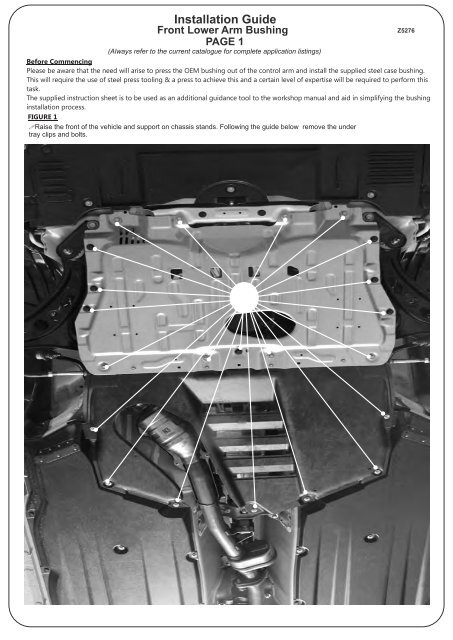
<strong>Installation</strong> <strong>Guide</strong>Front Lower Arm BushingPAGE 1(Always refer to the current catalogue for complete application listings)Before CommencingPlease be aware that the need will arise to press the OEM bushing out of the control arm and install the supplied steel case bushing.This will require the use of steel press tooling & a press to achieve this and a certain level of expertise will be required to perform thistask.The supplied instruction sheet is to be used as an additional guidance tool to the workshop manual and aid in simplifying the bushinginstallation process.FIGURE 1Raise the front of the vehicle and support on chassis stands. Following the guide below remove the undertray clips and bolts.Z5276
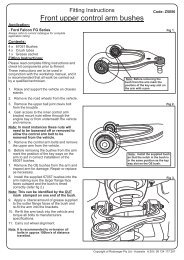
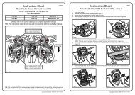
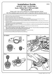
FIGURE 2<strong>Installation</strong> <strong>Guide</strong>Front Lower Arm BushingPAGE 2(Always refer to the current catalogue for complete application listings)Remove the front lower control arm ball joint split pin and loosen the locking nut. To release the ball jointtaper from the cast wheel hub use a suitable ball joint puller or alternatively use a copper faced hammer andstrike the face of the wheel hub to release the taper by impact force.Note!: Please ensure that you do not strike the face of the ball joint thread as damage may occur. It is good practiceto leave the locking nut part threaded onto the ball joint stud so as to reduce the risk of damage occurring.Strike the wheel hub as indicated below.Z5276*FIGURE 3Remove the front lower control front retaining plate & rear eye bolt as indicated below. Remove thecomplete arm from the vehicle.*
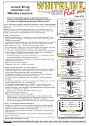
<strong>Installation</strong> <strong>Guide</strong>Front Lower Arm BushingPAGE 3Z5276FIGURE 4Mount the control arm in the press upside down using suitable press tools and press the bushing out ofthe arm.Note!: Ensure the arm is mounted upside down in the press. This will eliminate any distortion or damage to the armduring the removal process.*FIGURE 5Turn the arm over and press the supplied bushing in from the (Topside)Note!: Ensure that the supplied bushing is pressed into the arm on the steel flange face and not on the syntheticelastometre otherwise in field service of the bushing may be compromised and premature failure of the bushing mayoccur.*
<strong>Installation</strong> <strong>Guide</strong>Front Lower Arm BushingPAGE 4Z5276FIGURE 6Orientation of the supplied bushing showing installation into the left hand lower control arm.Ensure flange face is fully seated up against steel arm face.FIGURE 7Lubricate the inner bushing bore and flange faces with the supplied grease and install the supplied steelpin into the main bushing. Lubricate the bore of the supplied smaller bushings and flange faces and stretchfit the bushing over the ends of the steel tube as depicted in the image below.
<strong>Installation</strong> <strong>Guide</strong>Front Lower Arm BushingPAGE 5Z5276FIGURE 8Re-install the arm into the vehicle and re-fit fasteners and torque to manufacturers specifications oralternatively use the torque settings indicated below.103 newton metres76 foot poundsFIGURE 9Torque the ball joint retaining nut & re- fit the split pin. Re-install the under tray and drive the vehicle tosettle the suspension back to pre installed ride height.Note!: Due to the alignment geometry changing from the installation of the bushing it is recommended that a wheelalignment be carried out immediately to eliminate any abnormal tyre wear. Re-torque all arm bolts.95 newton metres70 foot pounds