Switch Repair Instructions for SOLITAIRE® FLASHLIGHTS - Maglite
Switch Repair Instructions for SOLITAIRE® FLASHLIGHTS - Maglite
Switch Repair Instructions for SOLITAIRE® FLASHLIGHTS - Maglite

You also want an ePaper? Increase the reach of your titles
YUMPU automatically turns print PDFs into web optimized ePapers that Google loves.
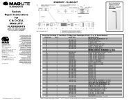
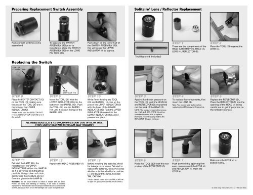
Preparing Replacement <strong>Switch</strong> AssemblySolitaire ® Lens / Reflector ReplacementReplacement switches comeassembled.To separate the SWITCHASSEMBLY (19) prior toinstallation, place the SWITCHASSEMBLY (19) on the LONGPIN TOOL (20).Push down on the lower half ofthe SWITCH ASSEMBLY (19),this will cause the UPPERINSULATOR (8) to pop up.Tool Required (Included)STEP 1These are the components of theHEAD ASSEMBLY (1), HEAD (2),LENS (4), REFLECTOR (5).STEP 2Place the TOOL (20) against theLENS (4).Replacing the <strong>Switch</strong>CENTERCONTACT (12)STEP 8Place the CENTER CONTACT (12)on the TOOL (20) making surethe pins of the TOOL (20) are inthe holes of the LOWERINSULATOR (13).*Note: make sure the SIDE CONTACT(11) and CENTER CONTACT (12) are inthe switch.SIDECONTACT (11)STEP 9Insert the TOOL (20) with theLOWER INSULATOR (13) into thebottom of the BARREL (10). Pushthe TOOL (20) into the BARREL(10) until it stops at the top of theBARREL (10).STEP 10While firmly holding the TOOL(20) and BARREL (10), line up thepins of the UPPER INSULATOR (8)with the holes of the LOWERINSULATOR (13). Push the UPPERINSULATOR (8) down into theLOWER INSULATOR (13) until itpresses into place.STEP 3Apply a hard even pressure onthe TOOL (20) until the LENS (4)and REFLECTOR (5) are pushedout the back of the HEAD (2).NOTE: The pressure required to removethe LENS (4) & REFLECTOR (5) will beconsiderably more than to replacethem and you will usually destroy theREFLECTOR (5) upon removal.STEP 4To replace the components, firstinsert the LENS (4).Note: You should wear a glove whenreplacing the LENS to avoid fingerprints.STEP 5Replace the REFLECTOR (5) ,Place the REFLECTOR (5) into theopening of the HEAD (2) beingcareful not to get fingerprints onthe reflective surface.ALL VISIBLE SEALS (3, 9, & 17) SHOULD HAVE A LIGHT COAT OF OIL ON THEM.IF NOT, LIGHTLY COAT WITH PETROLEUM JELLY (VASELINE ® )STEP 11Reinstall the LAMP (6) in thereceptacles of the UPPERINSULATOR (8). Adjust the LAMP (6)so it is as vertical and straight aspossible. Using a clean soft cloth,gently wipe the moisture and oilfrom the glass on the LAMP (6).STEP 12Replace the HEAD ASSEMBLY (1)STEP 13Be<strong>for</strong>e installing the batteries, check<strong>for</strong> leakage or corrosion. Reinstall orreplace the batteries, (one/AAA seriesalkaline only) install with the positive(+) end toward the lamp. ReinstallTAIL CAP (14).*Note: always make sure the TAIL CAP (14)is tight <strong>for</strong> good positive electrical contact.STEP 6Place the TOOL (20) over the rearportion of the REFLECTOR (5).STEP 7Push down firmly applying firmeven pressure until the LENS (4)and REFLECTOR (5) meet theLENS (4).Make sure the LENS (4) isseated evenly.WARNING: Do not allow children to install or tamper with the lamp.Protect the lamp from bending or twisting. If the lamp is installedimproperly or if the leads from the lamp are twisted so as to contact oneanother, this could short circuit the flashlight and cause heat generation. © 2004 Mag Instrument, Inc. 421-000-447 8/04