Switch Repair Instructions for SOLITAIRE® FLASHLIGHTS - Maglite
Switch Repair Instructions for SOLITAIRE® FLASHLIGHTS - Maglite
Switch Repair Instructions for SOLITAIRE® FLASHLIGHTS - Maglite

Create successful ePaper yourself
Turn your PDF publications into a flip-book with our unique Google optimized e-Paper software.
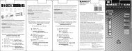
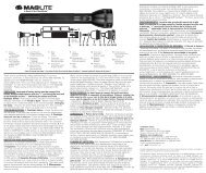
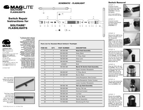
<strong>FLASHLIGHTS</strong><strong>Switch</strong> <strong>Repair</strong><strong>Instructions</strong> <strong>for</strong>SOLITAIRE ®<strong>FLASHLIGHTS</strong>SCHEMATIC - FLASHLIGHT<strong>Switch</strong> RemovalSTEP 1Unscrew (counterclockwise) and removethe entire TAIL CAPASSEMBLY (14) andthe battery.Note: A spare LAMP (8) islocated in the TAIL CAP (20).STEP 2Unscrew (counterclockwise) and removethe entire HEADASSEMBLY (1)CORPORATE OFFICEMAG INSTRUMENT, INC.1635 S. Sacramento Ave.P.O. Box 50600Ontario, Cali<strong>for</strong>nia U.S.A. 91761-1083Website: www.maglite.comWarranty: Tel: (800) 283-5562 or(909) 947-1006Fax: (909) 947-5041E-mail: warranty@magmail.comSales & Parts:Tel: (800) 289-6241 • (909) 947-1006E-mail: salesdesk@magmail.com©2004 MAG INSTRUMENT, INC.421-000-447 8/04Tool required toreplace the switchin the Solitaire®.(included)The distinctive shapes, styles andoverall appearances of all Mag®flashlights, and thecircumferential inscriptionsextending around the heads of allMag® flashlights are trademarksof Mag Instrument, Inc. Thecircumferential inscription on thehead of every flashlight signifiesthat it is an original Mag®flashlight and part of the Mag®family of flashlights. U.S.Trademark Registrations <strong>for</strong> theshape, style and overallappearance trademarks of Mag®flashlights and <strong>for</strong> circumferentialinscription trademarks of Mag®flashlights include Nos. 1,808,998;2,074,795; 2,687,693; 2,745,460;2,765,978 and 2,765,979.The Solitaire® Single Cell AAAflashlight is covered by one ormore pending patent applicationsand U.S. Patent Nos. 4,577,263;4,656,565; 4,658,336; 4,819,141;4,851,974; 4,864,474; 4,899,265;4,942,505; 5,003,440; 5,052,602;5,113,326; 5,143,441; 5,207,363;5,207,502; 5,293,307; 5,349,506;6,135,611; 6,170,960; Des.308,109. and by <strong>for</strong>eign patents.Parts List <strong>for</strong> Standard Black Solitaire ® FlashlightITEM NO QTY. PART NUMBER DESCRIPTION1 1 108-000-089 Head Sub-Assembly2 1 220-000-055 Head, Black3 1 108-000-067 'O' Ring, Head4 1 108-000-083 Clear Lens5 1 108-000-084 Reflector6 1 LK3A001 Bulb7 1 108-000-269 Barrel & <strong>Switch</strong> Sub-Assembly8 1 * Upper Insulator Receptacle9 1 108-000-067 'O' Ring, Barrel10 1 220-000-067 Barrel, Black11 1 * Lamp Receptacle, Side Contact12 1 * Lamp Receptacle, Center Contact13 1 * Lower Insulator Receptacle14 1 108-000-190 Tail cap Sub-AssemblySTEP 3Remove the LAMP (6) bypulling it straight out ofthe receptacles.WARNING: Do not allow children toinstall or tamper with the lamp.Protect the lamp from bending ortwisting. If the lamp is installedimproperly or if the leads from thelamp are twisted so as to contact oneanother, this could short circuit theflashlight and cause heat generation.STEP 4Insert the end of the TOOL(20) with the longest pinprotrusion into the bottomof the BARREL (10). Rotatethe tool until the two pinsenter the two holes in thebottom of the LOWERINSULATOR (13).STEP 5Place the TOOL (20) andthe BARREL (10) on a flatsurface and push down onthe BARREL (10). TheUPPER INSULATOR (8)will move upward andseparate from the LOWERINSULATOR (13).STEP 6You can now remove theUPPER INSULATOR (8)from the BARREL (10).15 1 108-000-069 Spring, Tail cap16 1 108-000-618 Electrical ContactTool has a longand short pinend. The longpins remove theswitch. The shortpins are to installthe switch.© 2004 Mag Instrument, Inc. 421-000-447 8/0417 1 108-000-204 Lip Seal18 1 220-000-156 Tail cap, Black19 * 108-000-085 <strong>Switch</strong> Assembly20 1 112-000-003 Short/Long Pin ToolSTEP 7Slowly lift the BARREL(10) off of the TOOL (20),the LOWER INSULATOR(13) should be on theTOOL (20). If not, tap theBARREL (10) lightly andthe LOWER INSULATOR(13) should fall out.
Preparing Replacement <strong>Switch</strong> AssemblySolitaire ® Lens / Reflector ReplacementReplacement switches comeassembled.To separate the SWITCHASSEMBLY (19) prior toinstallation, place the SWITCHASSEMBLY (19) on the LONGPIN TOOL (20).Push down on the lower half ofthe SWITCH ASSEMBLY (19),this will cause the UPPERINSULATOR (8) to pop up.Tool Required (Included)STEP 1These are the components of theHEAD ASSEMBLY (1), HEAD (2),LENS (4), REFLECTOR (5).STEP 2Place the TOOL (20) against theLENS (4).Replacing the <strong>Switch</strong>CENTERCONTACT (12)STEP 8Place the CENTER CONTACT (12)on the TOOL (20) making surethe pins of the TOOL (20) are inthe holes of the LOWERINSULATOR (13).*Note: make sure the SIDE CONTACT(11) and CENTER CONTACT (12) are inthe switch.SIDECONTACT (11)STEP 9Insert the TOOL (20) with theLOWER INSULATOR (13) into thebottom of the BARREL (10). Pushthe TOOL (20) into the BARREL(10) until it stops at the top of theBARREL (10).STEP 10While firmly holding the TOOL(20) and BARREL (10), line up thepins of the UPPER INSULATOR (8)with the holes of the LOWERINSULATOR (13). Push the UPPERINSULATOR (8) down into theLOWER INSULATOR (13) until itpresses into place.STEP 3Apply a hard even pressure onthe TOOL (20) until the LENS (4)and REFLECTOR (5) are pushedout the back of the HEAD (2).NOTE: The pressure required to removethe LENS (4) & REFLECTOR (5) will beconsiderably more than to replacethem and you will usually destroy theREFLECTOR (5) upon removal.STEP 4To replace the components, firstinsert the LENS (4).Note: You should wear a glove whenreplacing the LENS to avoid fingerprints.STEP 5Replace the REFLECTOR (5) ,Place the REFLECTOR (5) into theopening of the HEAD (2) beingcareful not to get fingerprints onthe reflective surface.ALL VISIBLE SEALS (3, 9, & 17) SHOULD HAVE A LIGHT COAT OF OIL ON THEM.IF NOT, LIGHTLY COAT WITH PETROLEUM JELLY (VASELINE ® )STEP 11Reinstall the LAMP (6) in thereceptacles of the UPPERINSULATOR (8). Adjust the LAMP (6)so it is as vertical and straight aspossible. Using a clean soft cloth,gently wipe the moisture and oilfrom the glass on the LAMP (6).STEP 12Replace the HEAD ASSEMBLY (1)STEP 13Be<strong>for</strong>e installing the batteries, check<strong>for</strong> leakage or corrosion. Reinstall orreplace the batteries, (one/AAA seriesalkaline only) install with the positive(+) end toward the lamp. ReinstallTAIL CAP (14).*Note: always make sure the TAIL CAP (14)is tight <strong>for</strong> good positive electrical contact.STEP 6Place the TOOL (20) over the rearportion of the REFLECTOR (5).STEP 7Push down firmly applying firmeven pressure until the LENS (4)and REFLECTOR (5) meet theLENS (4).Make sure the LENS (4) isseated evenly.WARNING: Do not allow children to install or tamper with the lamp.Protect the lamp from bending or twisting. If the lamp is installedimproperly or if the leads from the lamp are twisted so as to contact oneanother, this could short circuit the flashlight and cause heat generation. © 2004 Mag Instrument, Inc. 421-000-447 8/04